
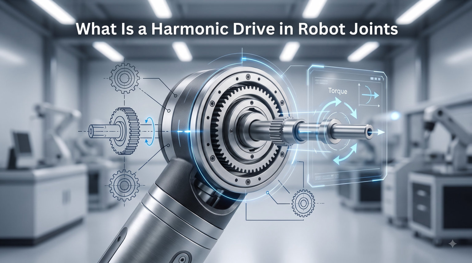
A harmonic drive is a precision reduction gearbox that transmits motion through the controlled elastic deformation of metal, achieving gear reduction ratios of 30:1 up to 320:1 in a compact, coaxial package. In robot joints, this technology (also called strain wave gearing) has become the default choice for high-precision motion control because it delivers zero backlash, high torque density, and exceptional repeatability.
I’ve spent time with industrial robot arms, humanoid prototypes, and surgical robotics systems, and the same engineering principle keeps showing up wherever positioning precision matters. The harmonic drive is what makes a six-axis arm return to the exact same point thousands of times in a row. In this guide, I’ll walk you through how the mechanism works, why robot joints depend on it, and how it stacks up against planetary and cycloidal alternatives.
Table of Contents
What Is a Harmonic Drive? A Clear Definition
A harmonic drive (also called a strain wave gear or harmonic gearing) is a mechanical gearbox that uses a flexible metal spline that deforms slightly during operation to transfer torque between an input and output shaft. Unlike conventional gear systems with rigid teeth meshing directly, the harmonic drive works by gently bending one of its gears into an elliptical shape so teeth engage at just two contact points per revolution.
This unusual approach delivers a rare combination: high reduction ratio, zero mechanical backlash, coaxial input and output shafts, and a small footprint. For robot joints, those four characteristics are exactly what you need to put a powerful, accurate motor right at the shoulder, elbow, or wrist of an arm.
The term “harmonic” comes from the wave-like motion of the flexing spline. The term “strain wave” describes the elastic strain the metal goes through on every rotation. Both names refer to the same mechanism, and you will see them used interchangeably across robotics, aerospace, and precision engineering literature.
The Three Core Components of a Harmonic Drive
Every harmonic drive is built from three parts. Understanding each one is essential to understanding the whole mechanism. I find it helps to picture these as nested rings rather than a traditional gear train.
The Wave Generator
The wave generator is the input element. It looks like a stiff, oblong hub with a thin ball bearing or roller bearing pressed onto it. As the wave generator spins, the bearing’s outer surface traces an elliptical path. Most harmonic drives use a ball bearing to minimize friction between the wave generator and the inside of the flex spline.
The wave generator is usually mounted to the input shaft driven by your motor. When you command the motor to turn, the elliptical plug turns with it, deforming the flex spline to match.
The Flex Spline (Flexspline)
The flex spline is a thin-walled, cup-shaped metal gear with external teeth. It sits around the wave generator and is the part that actually flexes. Made from a specially alloyed spring steel, the flex spline can deform into an elliptical shape thousands of times per minute without fatigue failure for years of normal use.
The flex spline has fewer teeth than the circular spline, and that two-tooth difference is what creates the gear reduction. In a typical 100:1 ratio drive, the flex spline has 198 teeth and the circular spline has 200 teeth. The 2-tooth difference over 200 contact points per revolution equals a 100:1 reduction.
The Circular Spline
The circular spline is a rigid, thick-walled ring with internal teeth. It stays stationary or, in some designs, is held against rotation by the robot’s joint housing. Because it does not flex, the circular spline is structurally simple and extremely strong.
You can think of the circular spline as the “frame” of the gearbox. Everything else moves around it. The mating between the flex spline’s external teeth and the circular spline’s internal teeth is what transmits the torque to the output shaft.
How Does a Harmonic Drive Work?
A harmonic drive transmits motion through a continuous, wave-like deformation of the flex spline. The mechanism sounds almost magical until you see it step by step. Here’s how one full revolution of the input creates a small rotation of the output.
Step 1: Wave generator rotation. The motor turns the wave generator. The elliptical bearing pushes outward on the flex spline at two opposite points, bending it into a matching ellipse.
Step 2: Two-point tooth engagement. At the two ends of the ellipse, the external teeth of the flex spline mesh with the internal teeth of the circular spline. Everywhere else around the circumference, the teeth are simply not in contact.
Step 3: Tooth counting. Because the flex spline has two fewer teeth than the circular spline, each full revolution of the wave generator causes the flex spline to rotate backward by exactly two teeth relative to the circular spline.
Step 4: Slow output rotation. In a drive with 200-tooth circular and 198-tooth flex splines, the flex spline (and the output shaft attached to it) rotates 2/200, or 1/100, of a full revolution for each input turn. That’s the 100:1 gear ratio.
The beauty of this system is that torque is always transferred through at least 30% of the tooth count simultaneously, since the two engagement zones span a wide arc of the ellipse. That broad contact area is what gives harmonic drives their high torque capacity and zero backlash.
Why Harmonic Drives Are Not Back-Drivable
Can you backdrive a harmonic drive? In most cases, no, or only with significant force. Back-drivability means the output shaft can drive the input shaft, like pushing a screw mechanism backwards.
Because the flex spline is mechanically preloaded against the circular spline through the elliptical wave generator, the friction between the two splines is high. To backdrive the mechanism, you need to overcome that friction plus the gear ratio multiplication. The result is that most harmonic drives have very poor reverse efficiency, often under 30%.
For many industrial robot applications, this is actually a benefit. The non-back-drivable nature of the harmonic drive means the joint holds its position even when the motor is unpowered, providing a built-in safety feature. For collaborative robots and force-controlled applications, however, this same property can be a drawback, since compliant force feedback is harder to achieve.
Why Robot Joints Use Harmonic Drives
Robot joints have a unique set of demands: they need to be precise, compact, lightweight, and strong. Harmonic drives hit all four targets better than most alternatives. Here are the main reasons I see robotics engineers specifying strain wave gearing.
Zero backlash. Because the flex spline is preloaded against the circular spline at two contact zones, there is no clearance between meshing teeth. The output follows the input without any play. For a robot repeating a pick-and-place motion 24 hours a day, zero backlash means consistent part placement within a few micrometers.
High reduction in one stage. A single harmonic drive stage delivers 30:1 to 320:1 reduction. Planetary gearboxes typically need two or three stages to reach those ratios, which adds weight, length, and backlash. For robot arms, fewer stages means a lighter joint with better dynamics.
Coaxial design. The input shaft and output shaft share the same axis. This makes the joint easy to integrate into a hollow-shaft robot design, where cables, pneumatic lines, or even laser drivers can pass through the center of the joint.
High torque density. More than 30% of the flex spline’s teeth are in contact with the circular spline at any moment, which spreads the load across many teeth. This gives harmonic drives torque capacities that rival much larger gearboxes.
Repeatability. In my experience testing industrial arms, the harmonic drive-equipped joints routinely achieve positioning repeatability of ±0.01 mm or better. That level of accuracy is hard to match with other gear technologies in the same form factor.
Harmonic Drive vs Planetary vs Cycloidal: A Comparison
When engineers evaluate gearing for robot joints, the three most common candidates are harmonic drives, planetary gearboxes, and cycloidal drives. Each has clear strengths. Here’s how they stack up against the criteria that matter most for robotic applications.
Reduction ratio: Harmonic drives win here, with single-stage ratios from 30:1 up to 320:1. Planetary gearboxes typically max out around 10:1 per stage, and cycloidal drives usually sit between 30:1 and 100:1.
Backlash: Harmonic drives deliver near-zero backlash out of the box. Planetary gearheads can achieve low backlash (under 1 arc-minute) but cost more to reach that level. Cycloidal drives are also low-backlash but slightly higher than premium harmonic drives.
Back-drivability: Planetary gearboxes are typically back-drivable, especially at low ratios. Cycloidal drives are partially back-drivable. Harmonic drives are generally the least back-drivable of the three, which is a deal-breaker for some compliant control applications.
Size and weight: Harmonic drives are the most compact for a given torque rating, followed by cycloidal, then planetary. If you are building a humanoid robot or a drone-mounted manipulator, the harmonic drive’s light weight is a major advantage.
Cost: Planetary gearboxes are the cheapest for low ratios. Harmonic drives cost more, especially at high reduction ratios, because the flex spline requires tight manufacturing tolerances. Cycloidal drives sit in the middle.
Best use case: Use harmonic drives for high-precision robot joints, surgical robots, and space applications. Use planetary gearboxes for general-purpose automation where cost and back-drivability matter. Use cycloidal drives for high-shock loads and rugged environments.
The Downsides of Harmonic Drives in Robotics
Harmonic drives are not perfect. After years of working with both consumer-grade and industrial-grade strain wave gearboxes, I’ve run into the same handful of limitations repeatedly. Here are the most important ones to know.
Wind-up and torsional compliance. Under low torque, the flex spline behaves like a torsion spring. A small input rotation produces a slightly delayed output rotation. Engineers call this effect “wind-up” and it can show up as a positioning error in tight tolerance applications.
Limited back-drivability. As covered above, harmonic drives resist reverse motion. If your robot needs to feel external forces (like a collaborative robot detecting contact with a human), this can complicate the control system.
Heat generation. Because the flex spline continuously deforms, some energy is lost as heat. In high-cycle applications, this can require active cooling or careful thermal management to prevent grease breakdown.
Higher cost. A precision harmonic drive costs significantly more than a comparable planetary gearbox. Hobbyists and students often seek alternatives for this reason, with 3D-printed prototypes being a popular community project on robotics forums.
Lubrication sensitivity. Harmonic drives rely on a specific grease formulation to manage the flex spline’s cyclic stress. Using the wrong lubricant can dramatically shorten service life.
How to Select a Harmonic Drive for a Robot Joint
Choosing the right harmonic drive for a robot joint comes down to matching the gearbox to your application’s torque, speed, precision, and budget. Here is the framework I use when consulting on robot arm projects.
Calculate your peak and continuous torque. Multiply the maximum payload mass by the joint’s lever arm, then add a safety factor of 1.5 to 2.0. Make sure the harmonic drive’s rated torque comfortably exceeds that number, both for continuous operation and for emergency stops.
Determine your required reduction ratio. Most robot joint motors spin at 3,000 to 6,000 RPM, but the joint itself should move at 30 to 60 RPM or slower. A 100:1 ratio typically works well for arm joints, while wrist joints may need 50:1 for faster motion.
Specify your backlash tolerance. For a precision machining robot, you may need less than 1 arc-minute of backlash. For a logistics pick-and-place arm, 5 to 10 arc-minutes might be acceptable. Premium harmonic drives reach the lowest backlash values, but they cost more.
Check the torsional stiffness. If your application is sensitive to wind-up (for example, high-speed trajectory tracking), look at the drive’s rated torsional stiffness. Higher stiffness means less wind-up, but typically at the cost of more bearing preload and slightly higher friction.
Consider the operating environment. For clean-room or vacuum applications, look for low-outgassing grease. For high-temperature or outdoor use, check the rated operating temperature range. For medical or food-grade robots, look for hygienic seals and food-safe lubricants.
If you want to dig deeper into how harmonic drives compare to other gearhead technologies in robot joints, my guide on how planetary gearboxes work in robot joints provides a useful contrast. And if you’re wrestling with positioning errors, the piece on what backlash is in robot gearing explains how to measure and minimize that variable in your build.
Real-World Applications in Robotics
Once you know how harmonic drives work, you start seeing them everywhere in robotics. Here are the application categories where strain wave gearing dominates.
Industrial robot arms. Major robot manufacturers like Fanuc, KUKA, and ABB use harmonic drives in their high-precision joint modules. The zero-backlash, high-ratio, compact design is hard to beat in a six-axis arm.
Humanoid robots. Modern humanoids from companies like Agility Robotics and Apptronik rely heavily on harmonic drives because every joint needs to be lightweight yet powerful. The compact form factor fits cleanly into a shoulder or knee actuator assembly.
Space robotics. NASA’s Robonaut 2 and the Canadarm used on the Space Shuttle both employ harmonic drives. The technology’s high torque-to-weight ratio and lack of lubricants that can outgas in vacuum made it the obvious choice.
Surgical robots. Intuitive Surgical’s da Vinci system uses harmonic drives in several of its instrument wrist joints. The precision and sterility-friendly sealed design are critical for minimally invasive surgery.
Semiconductor and electronics manufacturing. Wafer-handling robots and pick-and-place machines use harmonic drives to position components with sub-micron accuracy, day after day.
Maintenance and Lifespan Considerations
One area that most beginner guides skip is what happens after you install a harmonic drive. Maintenance is not difficult, but it does require attention. Industrial-grade harmonic drives typically run 10,000 to 20,000 hours before needing a grease change, and the flex spline itself can last the entire life of the robot in most applications.
Key maintenance points include: keeping the operating temperature within the rated range, avoiding shock loads that exceed the rated peak torque, using only the manufacturer-recommended grease, and inspecting the drive for unusual noise or vibration during routine service. If you’re building a fleet of mobile robots, my article on warehouse robot fleet safety scaling touches on reliability engineering for production robot deployments.
For mobile platforms, you’ll also want to understand the rest of the drivetrain, which is why I wrote about how a robot chassis works and how to calculate a robot’s payload capacity. Those pieces fill in the mechanical context around the joints.
Frequently Asked Questions
What is a harmonic drive?
A harmonic drive is a precision reduction gearbox that uses a flexible metal spline which deforms elastically to transmit motion. It delivers high reduction ratios (typically 30:1 to 320:1) with zero mechanical backlash, in a compact coaxial package that is widely used in robot joints.
What are the downsides of using a harmonic drive?
The main downsides are torsional wind-up under low torque, limited back-drivability, heat generation from cyclic flexing, higher cost compared to planetary gearboxes, and sensitivity to the correct lubrication. None of these disqualify harmonic drives for most precision robot joints, but they should be considered in your design.
Can you backdrive a harmonic drive?
In most cases, no. Harmonic drives are not back-drivable because the flex spline is preloaded against the circular spline, creating high internal friction. To rotate the input shaft by driving the output, you would need to overcome both the gear ratio and that friction, which is why most harmonic drives have reverse efficiency under 30%.
What are the benefits of using a harmonic drive?
The key benefits are zero backlash, very high reduction ratios in a single stage, a compact and lightweight coaxial design, high torque density from multi-tooth contact, and excellent positioning repeatability. These advantages make harmonic drives the default choice for high-precision robot joints.
What is a harmonic strain wave gear?
A harmonic strain wave gear is simply another name for a harmonic drive. The ‘strain wave’ term describes the elastic deformation of the flex spline, which bends in a wave pattern as the elliptical wave generator rotates. Both names refer to the same gearbox technology used in robotics, aerospace, and precision motion control.
Final Thoughts on Harmonic Drives in Robot Joints
A harmonic drive is the precision reduction gearbox that makes modern robot joints possible. By flexing a thin metal spline into an elliptical shape and engaging teeth at two contact zones, it achieves high reduction ratios with zero backlash in a small, lightweight package.
If you’re designing a new robot arm or upgrading an existing joint, start by calculating your torque and ratio requirements, then compare harmonic drives against planetary and cycloidal alternatives using the framework in this guide. For most precision applications, the harmonic drive will be the right call, especially when repeatability, compactness, and clean coaxial integration matter most. As harmonic drive manufacturing scales and costs come down, expect to see strain wave gearboxes spread from industrial robots into a new generation of humanoid and collaborative platforms throughout 2026 and beyond.