
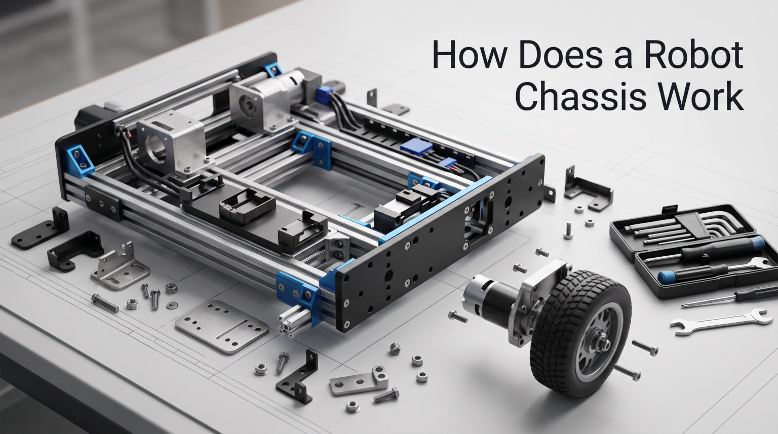
If you have ever wondered how a robot stays upright, carries weight, and moves with precision, the answer starts with one component. When someone asks how does a robot chassis work, they are really asking about the foundation that makes every mobile robot functional. I have spent years building, breaking, and rebuilding robots, and the chassis is always where the story begins.
A robot chassis is the structural frame that supports every other component in a robot. It holds the motors, wheels, battery, controller, and sensors in place while withstanding the forces of movement. Without a solid chassis, even the most advanced software and sensors cannot keep a robot moving reliably.
Our team at Smashing Robotics has worked with everything from simple two-wheel beginner kits to heavy-duty warehouse platforms. Along the way, we learned that understanding the chassis changes how you approach every other part of robotics. The frame dictates your payload, your speed, and your turning ability.
This guide breaks down what a robot chassis is, how it functions, what components make it up, and how the whole system works together to produce movement. Whether you are building your first Arduino robot or evaluating an industrial platform, you will find practical explanations here.
We will keep the technical jargon manageable while still covering the engineering principles that matter. Let us start with the basics.
Table of Contents
What Is a Robot Chassis?
A robot chassis is the mechanical base or structural frame of a robot that carries all components and provides the platform for locomotion. Think of it as the skeleton of the robot. It supports the motors, drivetrain, power system, electronics, and sensors while absorbing the physical stresses of movement.
The chassis converts rotational force from motors into actual travel across a surface. It does this through a drivetrain that includes wheels, tracks, or legs. The specific configuration determines how the robot steers, how fast it can go, and how much weight it can carry.
In mobile robotics, the chassis and the drivetrain work as a single integrated system. You will often see the term mobile robot chassis used to describe a complete platform that includes the frame, motors, wheels, and sometimes the motor controllers. This is different from a bare frame, which is only the structural shell without any drive components.
People sometimes confuse a chassis with a full robot. The key difference is that a chassis does not include the brain. It provides motion capability, but a separate controller or computer tells it what to do. That controller can be anything from a simple Arduino board to a powerful Jetson Nano or an industrial PLC.
Understanding this distinction helps you make better decisions when shopping for parts or designing a custom build. You can upgrade the brain without replacing the chassis, and you can swap drivetrain components without rebuilding the entire frame.
Core Functions of a Robot Chassis
A robot chassis serves several essential jobs at the same time. Let us break down the five core functions that every chassis must perform well.
1. Structural Support
The chassis holds everything together. It must be rigid enough that components do not shift during movement but light enough that the motors are not overloaded. A poorly designed frame flexes under load, which throws off sensor readings and causes erratic behavior.
I once built a robot with a thin acrylic frame that bent every time the robot accelerated. The bending shifted the wheel alignment just enough to make the robot drift to one side. Replacing the frame with aluminum fixed the problem instantly.
2. Weight Distribution
Where you place the battery, motors, and electronics on the chassis directly affects stability. A heavy battery mounted too high creates a top-heavy robot that tips over during turns. Good chassis design positions weight low and centered between the wheels.
The center of gravity is the single most important factor in robot stability. Every component you add shifts that center. A well-planned chassis accounts for all components before any drilling or cutting begins.
3. Motion Translation
The chassis converts motor rotation into movement through the drivetrain. Gears, belts, or direct shafts transfer torque from the motor to the wheels. The chassis must hold these components in precise alignment to prevent binding and power loss.
Even a fraction of a millimeter of misalignment can cause noticeable performance drops. Bearings and precision-machined mounts help maintain the alignment that efficient power transfer requires.
4. Component Protection
Motors, wiring, and circuit boards need physical protection from impacts, dust, and moisture. The chassis acts as a shield, especially in industrial settings where robots encounter debris and collisions on a daily basis.
Outdoor and warehouse robots face additional challenges. Their chassis must resist water, dust, and chemical exposure. This is where material choice and enclosure design become critical decisions.
5. Mounting Platform
Every sensor, bracket, and cable needs a place to attach. The chassis provides organized mounting points so you can add components without drilling random holes or using excessive adhesives. Competition builders and industrial engineers both rely on standardized mounting patterns for this reason.
Aluminum extrusion frames solve this problem beautifully. Their slotted rails let you bolt components anywhere along the length, which means you can reconfigure your layout without buying new parts.
These five functions overlap constantly. Structural support and weight distribution affect each other directly. A chassis that is too flexible cannot maintain proper weight balance, and poor weight balance puts extra stress on the structure.
Main Components of a Robot Chassis
Every robot chassis, from a simple hobby kit to a warehouse automation platform, shares five main component groups. Let me walk through each one in detail.
1. Structural Frame
The frame is the backbone of the entire chassis. It defines the shape, size, and rigidity of the robot. Common frame materials include aluminum, steel, acrylic, and HDPE plastic. Aluminum is the most popular choice because it offers an excellent strength-to-weight ratio.
Frames come in several construction styles. Flat plate designs are simple and common in beginner kits. Extrusion-based frames use slotted aluminum profiles that let you bolt components anywhere along the rail. Tubular frames provide maximum rigidity for heavy-duty applications.
The frame must account for two key dimensions: wheelbase and track width. The wheelbase is the distance between front and rear wheels. The track width is the distance between left and right wheels. Both dimensions affect stability, turning radius, and overall handling.
A longer wheelbase improves straight-line stability but increases the turning radius. A wider track width improves lateral stability but can make the robot too wide for doorways and narrow passages.
2. Drivetrain and Locomotion
The drivetrain includes everything that converts motor power into movement. This covers motors, wheels, gears, shafts, and bearings. Most beginner robots use DC motors with attached gearboxes that reduce speed while increasing torque.
The gear ratio determines the tradeoff between speed and torque. A high gear ratio gives you more pushing power but lower top speed. A low gear ratio gives you speed but reduces the ability to climb inclines or carry heavy loads.
Wheel selection matters more than people realize. Larger wheels travel farther per rotation but require more torque to turn. Smaller wheels are easier to drive but limit ground clearance. The wheel material also affects traction on different surfaces.
Competition builders emphasize a practice called two-point shaft support. This means each axle is supported by bearings on both sides of the wheel rather than just one. Without proper shaft support, axles bend, wheels wobble, and power is wasted.
3. Power System
The power system includes the battery, wiring, and power distribution. Most mobile robots use lithium-based batteries because they offer high energy density compared to older chemistries like NiMH or lead-acid.
The battery must be secured firmly to the chassis to prevent shifting during acceleration or turns. A loose battery can disconnect mid-operation, causing the robot to stop abruptly or behave unpredictably.
Battery placement directly affects center of gravity. A common mistake is mounting the battery on top of the robot, which raises the center of gravity and makes the robot prone to tipping. Experienced builders mount batteries as low and as centered as possible on the frame.
4. Control Electronics
Control electronics include the motor controller, main processor, and communication modules. The motor controller sits between the brain and the motors, translating commands into electrical signals that drive the motors at specific speeds.
Many beginners struggle with motor controller integration. The controller must match the voltage and current requirements of your motors. Undersized controllers overheat and fail, while oversized ones add unnecessary cost and weight.
For more advanced builds, a single-board computer like a Raspberry Pi or Jetson Nano handles high-level processing. It sends movement commands to the motor controller, which handles the low-level electrical work of driving the motors.
5. Sensors and Feedback
Sensors tell the robot where it is and what is around it. Encoders on the motors report wheel rotation for odometry calculations. An IMU, or inertial measurement unit, tracks orientation and acceleration. Ultrasonic and infrared sensors detect obstacles in the path.
The chassis must provide stable mounting points for these sensors. Vibrations from the drivetrain can introduce noise into IMU readings, which degrades navigation accuracy over time. Rubber isolation mounts help dampen these vibrations.
How Does a Robot Chassis Work Step by Step
Understanding how does a robot chassis work means following the path from a software command to physical movement. Here is the process broken into five clear steps.
Step 1: Command Generation
The robot controller receives a movement command. This could come from an autonomous navigation algorithm, a remote control signal, or a pre-programmed path. The command specifies a target velocity, direction, or destination.
In a simple remote-controlled robot, this command comes directly from a joystick or transmitter. In an autonomous robot, the command is generated by software that processes sensor data and decides where the robot should go next.
Step 2: Motion Planning and Kinematics
The control system uses kinematics to translate the desired movement into individual wheel speeds. For a differential drive robot, turning left means the right wheel spins faster than the left wheel. The math behind this translation depends entirely on the chassis type.
For more advanced robots, this step includes path planning. The system calculates a route around obstacles and feeds waypoint commands to the motor controllers in sequence.
Step 3: Motor Control Signal
The motion commands reach the motor controller as electrical signals. The controller adjusts the voltage and current sent to each motor. In a closed-loop control system, the controller reads encoder feedback and adjusts in real time to maintain the target speed.
Closed-loop control is what separates precise robots from wobbly ones. Without feedback, a motor might spin at different speeds depending on battery charge level or surface friction. The feedback loop corrects these variations automatically.
Step 4: Mechanical Actuation
The motors convert electrical energy into rotational force. Gearboxes reduce the rotational speed while multiplying the torque output. This torque travels through shafts and bearings to the wheels, tracks, or legs.
The chassis structure must absorb the reaction forces from this actuation. Poorly built frames vibrate and flex under load, which wastes energy and accelerates wear on mechanical components.
Step 5: Feedback and Odometry
As the robot moves, encoders count wheel rotations to estimate distance traveled. This process, called odometry, lets the robot track its approximate position over time. The IMU provides additional orientation data that complements the wheel measurements.
However, odometry is not perfect. Wheel slippage introduces errors that accumulate over distance. Advanced robots combine odometry with camera data, lidar scans, or GPS to correct these drift errors and maintain accurate positioning.
This feedback loop runs continuously during operation. The controller sends commands, motors respond, sensors measure the result, and the controller adjusts. This cycle happens dozens or hundreds of times per second, which is what gives a well-tuned robot its smooth, responsive movement.
Common Types of Robot Chassis
Not all robot chassis move the same way. The locomotion type determines maneuverability, speed, and complexity. Here are the four most common types you will encounter in 2026.
Differential Drive
Differential drive is the most common chassis type in hobby and educational robotics. It uses two independently controlled drive wheels, usually with one or more passive caster wheels for balance. By varying the speed of each wheel, the robot can move forward, backward, and turn in place.
This design is simple, affordable, and well-supported by tutorials and community resources. Its main limitation is that it struggles on uneven terrain because the caster wheels can catch on obstacles and lift the drive wheels off the ground.
Ackermann Steering
Ackermann steering works just like a car. It uses front wheels that pivot for steering and rear wheels that provide drive power. This type is common in larger robots and outdoor platforms because it handles higher speeds and rough surfaces well.
The tradeoff is that Ackermann robots cannot turn in place. They have a minimum turning radius determined by their wheel geometry. This limits maneuverability in tight indoor spaces but matters less for outdoor or warehouse aisle navigation.
Mecanum and Omni-Directional
Mecanum wheels use angled rollers around the rim that allow movement in any direction, including sideways. This gives omni-directional mobility without needing to rotate the chassis first.
Warehouse robots and platforms that work in tight aisles benefit greatly from this design. The downside is higher cost, more complex control mathematics, and reduced efficiency compared to standard wheels. Mecanum robots also require perfectly flat floors to perform well.
Tracked Chassis
Tracked robots use continuous belts instead of individual wheels. This design distributes weight over a larger surface area, which provides excellent traction on loose soil, sand, gravel, or uneven surfaces. Military, agricultural, and inspection robots often use tracks.
Tracks add mechanical complexity and significant weight. They also consume more power than wheeled designs of similar size. For most indoor applications, wheels are the better and more efficient choice.
Materials Used in Robot Chassis Construction
The material you choose for your robot frame affects weight, strength, cost, and ease of fabrication. Here is a comparison of the most common options available to builders.
Aluminum
Aluminum is the go-to material for most robot builders. It is lightweight, strong, easy to cut and drill, and available in standardized extrusion profiles. Aluminum extrusion systems let you build and modify frames without welding or specialized tools. Most intermediate and advanced hobby robots use aluminum as their primary structural material.
Steel
Steel provides maximum strength and rigidity. It is used in heavy-duty and industrial robots that carry large payloads or operate in demanding environments. The downside is weight, which reduces speed and increases motor power demands. Competition robots sometimes use steel selectively for critical structural pieces where aluminum would flex too much.
Acrylic
Acrylic is popular in beginner kits because it is cheap, lightweight, and visually appealing. However, acrylic is brittle and cracks under impact or stress concentration at drilled holes. It works fine for lightweight educational robots but is not suitable for anything that might collide with obstacles or carry significant weight.
HDPE
HDPE, or high-density polyethylene, is a durable plastic that resists impacts and vibration. It is lighter than aluminum and easier to machine than steel. Many commercial robot platforms use HDPE for base plates and motor mounts because it dampens vibration and does not crack like acrylic.
Carbon Fiber
Carbon fiber offers the best strength-to-weight ratio of any common chassis material. It is expensive and difficult to work with, requiring specialized tools and safety precautions during cutting. Carbon fiber appears mainly in high-end competition robots and research platforms where weight savings justify the cost.
For most builders, aluminum offers the best balance of performance and practicality. If your budget is tight, HDPE or acrylic works for light robots under a few pounds.
Key Specifications to Understand
When evaluating a robot chassis, several specifications tell you what the platform can actually do. Here are the ones that matter most for any build.
Payload Capacity
Payload capacity is the maximum weight the chassis can carry while maintaining acceptable performance. This includes the robot’s own components plus any additional load like sensors, manipulators, or cargo. Always leave a safety margin of at least 20 percent below the rated capacity.
Maximum Speed
Maximum speed depends on motor RPM, gear ratio, and wheel diameter. Faster is not always better. High-speed robots need more sophisticated control systems, better braking, and more precise sensor feedback to operate safely.
Turning Radius
Turning radius defines how tightly the robot can turn. Differential drive robots can turn in place with a zero turning radius. Ackermann robots have a fixed minimum radius based on their wheel geometry and steering angle limits.
Ground Clearance
Ground clearance is the space between the bottom of the chassis and the ground surface. Higher clearance lets the robot navigate obstacles and rough terrain without scraping. Lower clearance improves stability by lowering the center of gravity.
Runtime
Runtime depends on battery capacity and the total power consumption of motors and electronics. A chassis that accommodates a larger battery will run longer but may need stronger motors to handle the extra weight. These factors are always interconnected.
These specifications interact with each other in important ways. Increasing payload often reduces maximum speed. Raising ground clearance can reduce stability. Understanding these tradeoffs helps you choose the right platform for your specific needs.
Choosing the Right Robot Chassis
Selecting a chassis depends on your project goals, budget, and experience level. Let me share what our team has learned from building dozens of robots over the years.
For Beginners
Start simple. A two-wheel differential drive kit with a pre-cut acrylic or aluminum base costs very little and teaches you the fundamentals of robot construction. Look for kits that include motors, wheels, and mounting hardware in one package. Avoid starting with complex designs like Mecanum or tracked systems.
Robotics communities on Reddit frequently suggest hacking old RC cars as a budget alternative. RC car chassis are sturdy, already include motors and wheels, and cost almost nothing if you have an old toy lying around. You just need to add your own controller and sensors.
For Intermediate Builders
At this stage, aluminum extrusion frames offer the flexibility to experiment and iterate. You can mount components anywhere along the rails, which means you can reconfigure your robot layout without buying a new frame. Look for 4WD platforms if you plan to add heavier components like a Jetson Nano or lidar sensor.
Motor controller integration is where intermediate builders hit the most trouble. Match your controller to your motors carefully, and always check the continuous and stall current ratings. A controller that is too small for your motors will overheat, throttle performance, or fail completely.
For Advanced and Industrial Use
Heavy-duty applications often require custom aluminum or steel frames built to specific requirements. These builds focus on payload, durability, and precision above all else. Two-point shaft support becomes non-negotiable at this level, and closed-loop control with encoder feedback is the standard rather than the exception.
Consider whether you need an off-the-shelf platform or a fully custom build. Commercial chassis save development time and come with documentation and support. Custom builds give you complete control over every dimension and specification but require significant design and fabrication effort.
Common Mistakes and How to Avoid Them
After years of building robots, here are the mistakes we see most often from beginners and intermediate builders alike.
Mounting the Battery Too High
This raises the center of gravity and causes tipping during turns and sudden stops. Always mount batteries as low as possible on the chassis, ideally directly above or between the drive wheels.
Skipping Proper Shaft Support
Axles supported on only one side wobble, bend, and waste power. Use bearings on both sides of each wheel to keep the axle aligned under load. This single change can dramatically improve performance and component lifespan.
Using Undersized Motor Controllers
Controllers that cannot handle your motor current will overheat and fail, often at the worst possible moment. Check the stall current rating of your motors and choose a controller rated comfortably above it. Heat sinks and ventilation also help extend controller life.
Ignoring Wire Management
Loose wires catch on wheels, snag on obstacles, and disconnect at critical moments. Use cable clips, zip ties, and routed channels to keep wiring organized and secured against the chassis.
Overlooking Ground Clearance
A chassis that scrapes the ground on every bump will not get far. Measure your clearance before finalizing the design, and account for suspension compression if your robot uses springs or shock absorbers.
Forgetting About Maintenance Access
You will need to reach motors, batteries, and controllers for repairs and upgrades. Design your chassis so critical components are accessible without disassembling the entire robot. A few extra access holes save hours of frustration later.
FAQ
What is a chassis on a robot?
A chassis on a robot is the structural frame that supports all components including motors, wheels, battery, and electronics. It provides the mechanical base for movement and absorbs the physical forces generated during operation.
How does a robot chassis work step by step?
A robot chassis works by receiving a movement command from the controller, translating it into individual wheel speeds using kinematics, sending motor control signals, converting electrical energy into mechanical rotation through the drivetrain, and using encoder feedback to close the control loop for precise movement.
What are the main components of a robot chassis?
The five main components of a robot chassis are the structural frame, the drivetrain with motors and wheels, the power system with battery and wiring, the control electronics including motor controllers, and the sensors such as encoders and IMUs that provide feedback.
What is the best type of robot chassis for beginners?
The best robot chassis for beginners is a two-wheel differential drive kit with a pre-cut acrylic or aluminum base. It is simple to assemble, affordable, well-documented, and teaches the fundamentals of robot construction without overwhelming complexity.
What are robot chassis made of?
Robot chassis are most commonly made of aluminum, which offers the best balance of strength and weight. Other materials include steel for heavy-duty builds, acrylic for cheap beginner kits, HDPE for durable plastic bases, and carbon fiber for high-end competition robots.
How do I choose a robot chassis for my project?
Choose a robot chassis based on your payload requirements, terrain type, budget, and experience level. Beginners should start with differential drive kits, intermediate builders benefit from aluminum extrusion frames, and advanced users often need custom builds with closed-loop control and heavy-duty materials.
Conclusion
Understanding how does a robot chassis work gives you the foundation for every robotics project you will ever undertake. The chassis is not just a piece of metal or plastic that holds parts together. It is the integrated system that translates commands into motion, distributes weight for stability, and provides the structural integrity that everything else depends on.
We covered the five core functions, five main component groups, the step-by-step working principle, and the most common chassis types and materials. We also shared the mistakes we have made so you can avoid them in your own builds.
If you are just starting out, grab a simple differential drive kit and begin experimenting. The best way to understand robot chassis is to build one, break it, and build it again better. Every iteration teaches you something new about weight distribution, motor integration, and structural design.
Keep building, keep testing, and keep learning. That is how every great robotics engineer started.