
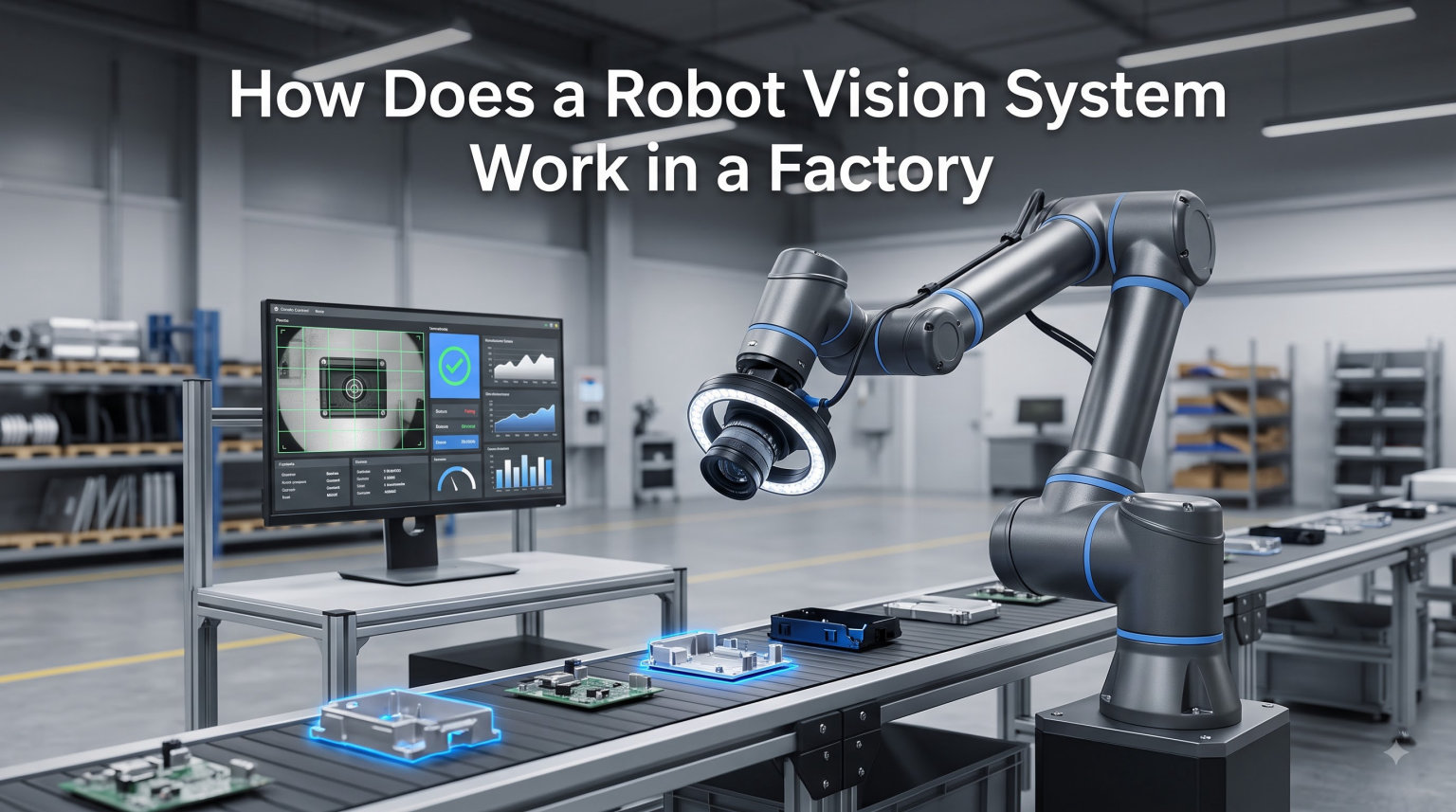
A robot vision system gives industrial robots the ability to see, measure, and react to the world around them. Inside a modern factory, this is what turns a blindly programmed arm into a flexible, decision-making worker that can find parts, inspect surfaces, and place components with sub-millimeter accuracy.
I have spent the last several years working with and writing about robotic automation, and the question of how a robot vision system works in a factory comes up constantly. Plant managers want to know what the cameras are actually doing. Engineers want to know what runs on the back end. This guide walks through the entire pipeline, from the lens on the line to the motor command at the robot wrist, with the practical detail that factory buyers need.
You will learn what a robot vision system is, the exact step-by-step process it follows, the hardware and software that make it work, where 2D and 3D vision diverge, and the most common factory applications. We will also cover the challenges that real teams hit on the floor and how AI is changing what these systems can do. If you want a deeper look at how vision connects to the gripper end of the arm, our piece on how robotic grippers work is a good companion read.
Table of Contents
What Is a Robot Vision System?
A robot vision system is a combination of camera hardware, lighting, processing electronics, and software algorithms that lets an industrial robot capture and interpret visual data from its environment. The system then converts that interpretation into coordinates, decisions, and motion commands that the robot controller can act on.
At its core, a robot vision system performs three jobs that human vision handles effortlessly. It detects that an object exists, determines where that object sits in space, and decides how the robot should respond. The cameras handle detection. The processors and software turn the picture into numbers. The robot controller turns the numbers into motion.
This is different from machine vision, which is the broader field of giving any machine visual feedback (often stationary inspection stations), and different from computer vision, which is the academic discipline of teaching computers to see in any context, from self-driving cars to medical imaging. Robot vision is the specific branch of computer vision that ends in a robot doing something physical in the real world.
How a Robot Vision System Works in a Factory: Step by Step
The whole process, from photon to motor torque, follows a clear four-step pipeline. Once you understand these four steps, every factory vision application makes sense, because they are all variations on the same theme.
Step 1: Image Capture
The factory robot vision camera fires, either on a fixed schedule or when a sensor (like a photo-eye) tells it a part is in position. Lighting has been set up to make the part’s features stand out. A single 2D shot, a stereo pair, a laser line, or a projected pattern lands on the image sensor as raw pixel data.
Step 2: Image Processing
The vision processor runs algorithms over the pixels. It removes noise, finds edges, looks for trained features, and matches what it sees against a stored model of the part. The output is a list of object positions, orientations, and confidence scores, typically in millimeters and degrees rather than pixels.
Step 3: Decision and Coordinate Transformation
The system translates those pixel-derived numbers into the robot’s coordinate frame. This is where calibration pays off. The robot now knows that a particular bolt, for example, is sitting 142.6 millimeters to the right, 38.2 millimeters forward, and rotated 17.4 degrees.
Step 4: Robot Action
The robot controller receives the target pose and plans a motion path that respects joint limits, collision zones, and approach angles. The arm moves, the gripper closes, and the cycle repeats. On a typical assembly line, the entire four-step loop runs in 200 to 500 milliseconds.
For a deeper look at the network plumbing that moves this data around, see our guide on how Wi-Fi control works on a robot, which covers the industrial protocols that often carry vision results.
Key Components of a Robot Vision System
Every robot vision system, whether it costs 2,000 dollars or 50,000 dollars, contains the same five building blocks. The differences show up in how they are implemented, not in what is present.
Cameras and Image Sensors
Area-scan cameras grab a full 2D picture in one shot and are the workhorse of factory vision. Line-scan cameras build an image one row at a time and are used on continuous webs like sheet metal, paper, or fabric. Smart cameras combine the sensor, processor, and lens into a single rugged unit, and they are the cheapest way to add vision to a station.
Lighting
Lighting is the single biggest factor in whether a vision system works. Backlights create a clean silhouette for measuring part dimensions. Ring lights, dome lights, and dark-field illuminators reveal surface defects. Structured light (projected patterns) and laser lines are the basis of most 3D systems. Get the lighting wrong, and no amount of software will save you.
Processors and Edge Hardware
The processor can be a small industrial PC, an embedded GPU box, an FPGA accelerator, or a smart camera with everything onboard. FPGAs are increasingly common for high-speed inspection because they process pixels in parallel with deterministic latency. Our explainer on FPGAs in robotics covers the trade-offs in more detail.
Software and Algorithms
The software stack includes the image processing library, the application logic, and increasingly, a trained neural network. The image library handles classic operations like thresholding, edge detection, blob analysis, and template matching. The application logic decides which features matter, what counts as a defect, and how the result is reported to the robot.
Robot Controller Interface
Finally, the vision system has to talk to the robot. Most modern systems use standard protocols like TCP/IP socket messaging, Profinet, or fieldbuses like EtherCAT. The robot controller subscribes to vision updates, queries the camera when needed, or accepts streamed pose data continuously.
2D vs 3D Robot Vision Systems
The single most important design choice in any robot vision system is whether to go 2D or 3D. The cost, complexity, and use cases diverge sharply, so the right call depends on what the robot is actually trying to do.
When 2D Vision Is Enough
2D vision is faster, cheaper, and simpler to deploy. It shines when the part is presented on a flat surface, the lighting can be controlled, and the robot only needs to know an X, Y position plus a rotation angle. Pick and place from a conveyor, label inspection, and simple presence checks are classic 2D jobs.
When 3D Vision Is Required
3D vision adds depth, which is essential for bin picking, where parts land in random orientations, or for any application that needs the robot to grasp over obstacles. Common 3D techniques include stereo vision (two cameras), laser triangulation, time-of-flight sensors, and structured light projectors. Each has trade-offs in accuracy, range, and price.
Choosing the Right Approach
For most first-time factory deployments, start with 2D. The integration effort is much lower, the cameras are a fraction of the price, and the algorithms are well understood. Move to 3D when the application genuinely requires it, not because 3D is newer. Over-engineering the vision stack is one of the most common ways I have seen budgets balloon.
Inside the Image Processing Pipeline
The image processing pipeline is where the magic happens, and it is the layer most engineers care about. Understanding it helps you debug systems, choose vendors, and decide what kind of training data you need.
Image Acquisition and Pre-Processing
Raw images from factory cameras are noisy, unevenly lit, and full of irrelevant detail. The first step is pre-processing, which applies a flat-field correction, a noise filter, and a histogram equalization to normalize the image. This step alone often determines whether later stages succeed or fail.
Feature Extraction and Pattern Matching
Once the image is clean, the system looks for features. In a traditional pipeline, this is template matching, where the system slides a stored pattern across the image and reports the location of the best match. Geometric feature matching uses edges, corners, and holes. Both approaches are fast, deterministic, and easy to debug.
Coordinate Transformation and Calibration
The pixel coordinates where the system found the part have to become robot coordinates. This happens through calibration, where the robot touches a known target and the system learns the math that converts pixels to millimeters. Hand-eye calibration, where the camera is mounted on the robot itself, is a special case that compensates for camera motion.
Pose Estimation and Confidence Scoring
For 3D applications, the system estimates a full six-degree-of-freedom pose (X, Y, Z, plus three rotations). Each result comes with a confidence score, and most production systems will reject a pick if the score falls below a threshold. Tuning that threshold is one of the most common engineering tasks in any robot vision deployment.
Common Factory Applications of Robot Vision
Robot vision shows up wherever the factory needs flexibility, precision, or quality assurance that fixed tooling cannot deliver. The same vision stack can serve wildly different applications, which is why it has become such a foundational technology.
Quality Inspection and Defect Detection
Vision-based inspection catches surface scratches, missing components, wrong labels, and dimensional out-of-tolerance parts at production speeds that no human can match. Modern systems can detect sub-millimeter defects and reject bad parts before they reach packaging.
Pick and Place and Bin Picking
This is the textbook robot vision application. A camera identifies a part on a conveyor or in a bin, the system calculates where the robot should grip, and the arm places it into the next operation. Bin picking is the harder variant, where parts overlap and occlude each other, which is why it usually requires 3D vision.
Assembly Verification
Vision confirms that the right part was placed in the right orientation before the next assembly step begins. This catches errors before they cascade down the line, and it is one of the highest-ROI applications in automotive and electronics manufacturing.
Machine Tending and Welding Guidance
Robots that load and unload CNC machines, presses, or injection molders use vision to find the raw stock and align the gripper. In welding, laser-guided vision tracks the joint in real time, compensating for thermal distortion and part variation that would otherwise ruin the weld.
AI and Deep Learning in Modern Robot Vision
Traditional rule-based vision handles controlled conditions well, but it struggles when parts vary, surfaces are complex, or defects look like the background. This is where AI and deep learning are quietly transforming the field.
Convolutional neural networks can be trained on hundreds of images to recognize good and bad parts, even when the differences are subtle or hard to describe in rules. Object detection models like YOLO can find dozens of part types in a single frame without any template. Foundation models for vision are now being applied to factory data, allowing systems to learn from far fewer labeled examples than before.
The trend I find most interesting is the move to physical AI infrastructure that combines vision, language, and action. A modern cell can take a natural language instruction, look at a scene, and decide what to pick without being explicitly programmed for that part. For a frank look at where this is hitting economic limits today, the recent piece on humanoid scaling challenges is worth a read.
Common Challenges and How to Overcome Them
Every factory vision project hits predictable problems. Knowing them ahead of time is half the battle, and there are practical fixes for nearly all of them.
Lighting Variability
Sunlight leaking through a window, flicker from overhead LEDs, and reflections from shiny parts are the top three causes of failed vision jobs. The fix is to control the light source: enclose the inspection station, use diffuse dome lighting, and consider polarizing filters for reflective surfaces.
False Positives and False Negatives
Quality teams typically hate false rejects even more than they hate escapes. The solution is to tune the confidence threshold carefully, use multiple inspection features in series, and run a structured test set through the system before going live. AI models can help, but they need representative training data.
Integration with Existing PLCs and Robots
The mechanical and electrical integration is often harder than the vision work itself. Fieldbus mismatches, handshake timing, and PLC scan cycles can all cause mysterious faults. Plan a dedicated integration sprint with both the vision vendor and the robot vendor in the same room.
Expectations Mismatch
Management often expects vision to be a magic switch. It is not. A realistic pilot takes 8 to 16 weeks, a working production cell takes 3 to 6 months, and a multi-station rollout can run a year. Setting those expectations early protects the project and the team.
Frequently Asked Questions
What is a robot vision system and how does it work?
A robot vision system is the combination of cameras, lighting, processing hardware, and software that gives an industrial robot the ability to see its environment. It works through a four-step pipeline: image capture, image processing, coordinate transformation, and robot action.
How do manufacturing robots work?
Manufacturing robots combine arms, controllers, and often vision systems. The controller executes a programmed motion path, while the vision system feeds back real-time data about part position, orientation, and quality. Together they automate tasks like welding, assembly, picking, and inspection.
What are vision systems in manufacturing?
Vision systems in manufacturing are cameras and software that inspect parts, guide robots, verify assemblies, and read codes. They replace or augment human visual inspection and enable robots to handle variability that fixed tooling cannot.
How do robot eyes work?
Robot eyes are typically industrial cameras with matched optics and lighting. The camera sensor converts light into digital pixels, and the processor runs algorithms that find features, match patterns, and estimate the position of objects so the robot can act on them.
What is the difference between robot vision and machine vision?
Machine vision is the broader category of giving any machine visual feedback, often for stationary inspection. Robot vision is the specific branch that ends with the robot moving and acting in the physical world, usually requiring real-time pose estimation and motion control.
How much does a robot vision system cost?
A simple 2D smart camera starts around 2,000 dollars. A mid-range 3D bin-picking cell with software, lighting, and integration can run 50,000 to 150,000 dollars. Custom AI vision systems for complex inspection can exceed 250,000 dollars fully installed.
The Future of Robot Vision in Factories
A robot vision system in a factory is no longer a luxury add-on. It is the perception layer that lets flexible automation actually work. The four-step pipeline of capture, processing, decision, and action is the same whether you are looking at a 2D label inspection or a 3D bin-picking cell. Start with the simplest vision that solves your problem, control your lighting, and plan a real integration budget.
For 2026 and beyond, the biggest shifts will come from AI-driven perception and edge processing, which together will make robot vision cheaper, more capable, and easier to deploy. If you are evaluating your first cell, pilot a 2D pick-and-place application, measure the throughput and quality gains, and then scale. The factories that get this right will define the next decade of manufacturing.