
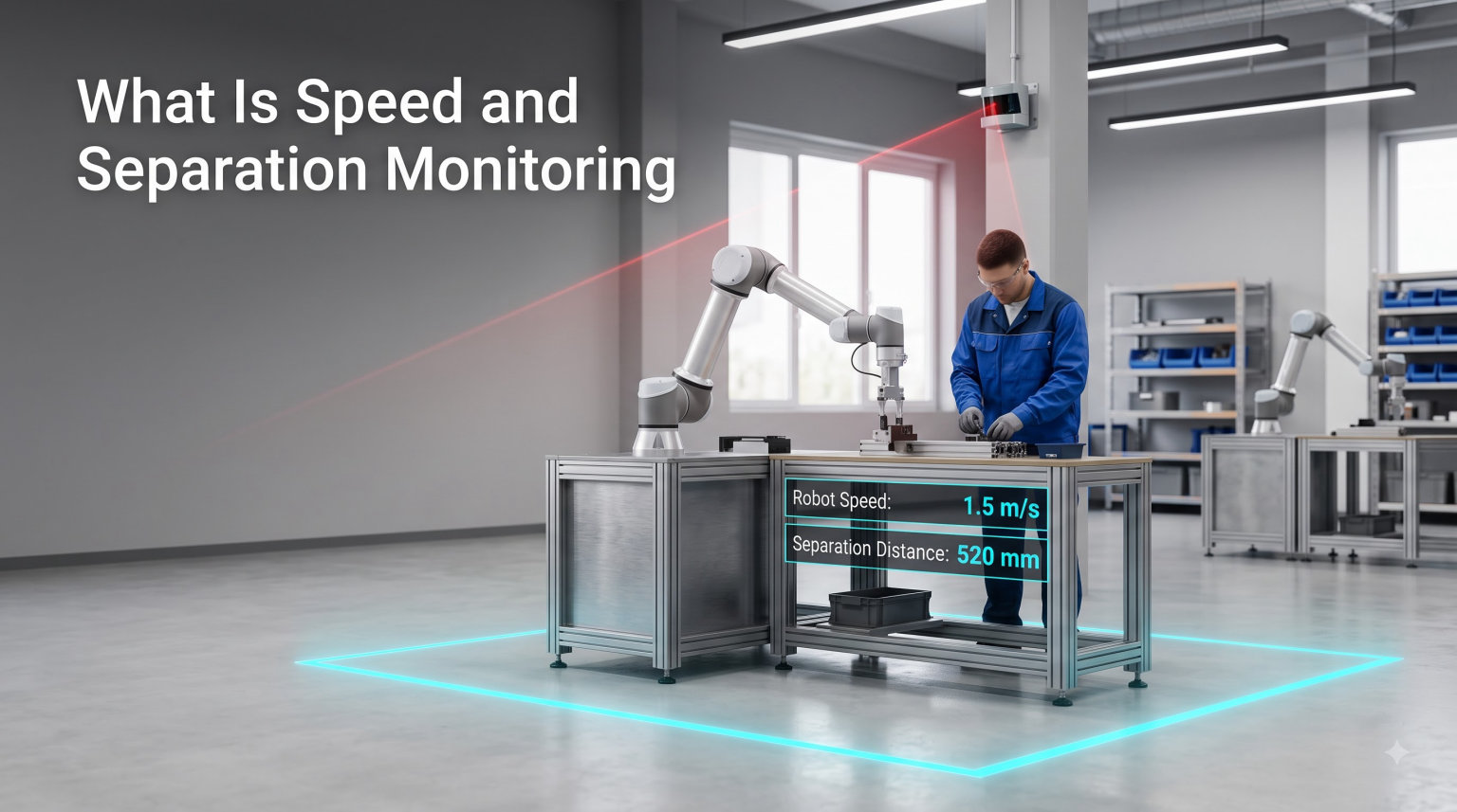
Speed and Separation Monitoring (SSM) is a collaborative robot safety function defined in ISO/TS 15066 and ISO 10218 that allows a robot and a human to share the same workspace. The area around the robot is continuously monitored, and when someone approaches, the robot initially slows down and eventually stops to maintain a minimum safe separation distance.
I have spent weeks reading ISO technical specifications, academic papers, and integrator field reports to put this guide together. Our team wanted to explain speed and separation monitoring in a way that actually helps safety engineers, integrators, and curious engineers who keep hearing the acronym but never see a clear breakdown. In the sections ahead, I will walk you through what SSM is, how it works, the standards that govern it, and how it compares to other cobot safety modes.
Before we get into the technical detail, it helps to know that SSM is one of four collaborative operation modes recognized by the international standards. It is the mode designed for situations where the robot keeps moving while people are nearby, which is why understanding it matters for any modern human-robot collaboration project.
Table of Contents
What Is Speed and Separation Monitoring (SSM) in Robotics
Speed and Separation Monitoring is a collaborative robot safety mode in which the robot continuously maintains at least a minimum separation distance from any human operator inside the shared workspace. The robot’s speed is dynamically adjusted based on how close a person gets, slowing as distance decreases and triggering a protective stop before contact can occur.
SSM is formally defined in two key documents. ISO 10218-1 and ISO 10218-2 cover industrial robot safety requirements, and the technical specification ISO/TS 15066 provides the detailed guidance for collaborative robot operation. Together, these standards describe SSM as a perception-based safety function that relies on real-time distance measurement.
What makes SSM different from a traditional caged robot cell is that the system never assumes the human is outside the work envelope. Instead, it actively watches the workspace, predicts where the operator is heading, and modulates robot motion accordingly. This makes SSM well suited to dynamic production environments where humans and robots perform interleaved tasks.
Core Characteristics of SSM
The defining behavior of any SSM system comes down to three observable actions. First, the system continuously measures the distance between the robot and any detected human. Second, it calculates a safe robot speed based on that distance, the robot’s reaction time, and the operator’s approach speed. Third, it enforces protective stops when the minimum separation distance threshold is crossed.
These three behaviors are what separate a true SSM implementation from a simple area scanner with a hard stop. A genuine SSM system is graded in its response, not binary, and that is the heart of why collaborative robots can move at all while people are present.
How Speed and Separation Monitoring Works
SSM operates on a continuous perception-and-control loop. Perception sensors detect the position of humans in the workspace, a safety-rated controller calculates the minimum allowed robot speed and the protective stop threshold, and the robot controller adjusts motion in real time. The loop runs at high frequency, often 50 Hz or more, so the system reacts faster than a human can move into danger.
From my reading of the ISO/TS 15066 technical specification, the working principle is straightforward in concept but demanding in implementation. The system needs a reliable picture of where every relevant person is at every moment, and it needs a credible model of how both the person and the robot will move over the next half-second to two seconds.
Perception Systems Used in SSM
Several sensor types feed the perception layer of an SSM system. Safety-rated laser scanners are common because they create horizontal protection zones around the robot base. 3D time-of-flight cameras and stereo vision systems add vertical coverage and can detect upper-body motion. Depth sensors mounted overhead provide top-down tracking, and wearable safety tags using ultra-wideband or RFID allow the system to follow specific authorized personnel.
Many production-grade SSM systems combine multiple sensor modalities. Sensor fusion improves robustness because no single technology is perfect in every lighting condition, occlusion scenario, or clutter level. A camera may lose track when a person is hidden behind a part bin, while a laser scanner cannot see over obstacles, so combining them yields a more dependable picture.
Dynamic Speed Adjustment
The most visible feature of SSM is the way the robot slows down as a person approaches. When the operator is far away, the robot can run at full collaborative speed. As the distance shrinks, the controller reduces the maximum allowed speed proportionally. When the operator crosses into the protective stop zone, the robot halts before contact is possible.
This gradual response is what lets collaborative robots stay productive. If the system only had an on-or-off safety stop, the robot would freeze every time a person walked past, which would defeat the purpose of human-robot collaboration. By tying allowed speed to measured distance, SSM keeps work flowing while the risk of contact stays within tolerable limits.
ISO Standards Context: ISO/TS 15066 and ISO 10218
SSM exists as a defined concept because the international safety standards explicitly describe it. ISO 10218-1, published by the International Organization for Standardization, covers safety requirements for the industrial robot itself, while ISO 10218-2 covers robot systems and integration. The technical specification ISO/TS 15066, titled “Collaborative robots,” fills in the details for collaborative operation.
According to these documents, there are four collaborative operation modes a robot system can use. They are safety-rated monitored stop, hand guiding, speed and separation monitoring, and power and force limiting. A system integrator selects one or more of these modes based on the risk assessment for the specific application.
ISO/TS 15066 also defines biomechanical limits for quasi-static and transient contact. Those limits tell engineers what pressures and forces a human body can tolerate briefly without injury, and they are what set the speed thresholds used in SSM. The standard also provides guidance on the minimum separation distance formula, which I cover in the next section.
If you are evaluating a cobot system for a real project, asking the vendor which clauses of ISO/TS 15066 their SSM implementation supports is a smart first step. It separates marketing claims from verifiable safety engineering, which matters when an incident triggers an audit.
Minimum Separation Distance Explained
The minimum separation distance is the closest the robot may come to an operator while still moving. It is calculated using a formula defined in ISO/TS 15066 that accounts for the robot’s stopping time, the operator’s approach speed, the perception system’s measurement uncertainty, and a safety margin. The robot must never get closer than this calculated distance while in motion.
The simplified form of the formula, as described in the technical specification, is:
S = (S_h + S_r + S_s + C) + Z
Where S_h is the operator’s contribution to the separation distance based on approach speed and reaction time, S_r is the robot’s stopping distance from its current speed, S_s is the safety margin related to perception system uncertainty, C is the intrusion distance, and Z is a position uncertainty term related to operator distance measurement.
Why the Formula Matters
Every term in the minimum separation distance equation is a tunable knob. Faster operators, slower perception systems, or robots with longer stopping distances all push the minimum distance outward. Engineers tune these values during risk assessment to find the largest distance that still leaves the robot productive.
In practice, I have seen integrators settle on protective stop thresholds in the range of a few hundred millimeters to over a meter, depending on payload, robot reach, and the worst-case approach speed they assume. The point is that the number is not arbitrary; it is the output of a defensible calculation that an auditor can trace back to the standard.
SSM vs Other Collaborative Robot Safety Modes
SSM is one of four collaborative operation modes, and choosing between them is one of the most common decisions integrators face. The other three are safety-rated monitored stop, hand guiding, and power and force limiting. Each addresses a different pattern of human-robot interaction, and the right choice depends on the task and the risk assessment.
Safety-rated monitored stop is the simplest mode. The robot runs at full speed when no one is in the workspace, and it halts whenever a person enters. Productivity drops sharply if operators cross into the robot area frequently, which is why many collaborative applications use SSM instead.
Hand guiding lets an operator physically move the robot by grasping an end-effector or a special handle, with safety-rated monitoring of the applied force and speed. It is ideal for teach-by-demonstration tasks and small-batch programming but not for high-throughput production.
Power and force limiting relies on the robot itself being inherently safe, with collaborative-rated designs that limit contact forces and pressures below biomechanical thresholds. PFL cobots are common in assembly and pick-and-place, but they typically handle lower payloads and lower speeds than SSM systems can.
When SSM Is the Right Choice
SSM shines when the application needs higher payload, longer reach, or higher cycle rates than a power and force limiting cobot can deliver, and when the workspace must remain open and barrier-free. Heavy-payload assembly, machine tending with industrial robots, and palletizing benefit from SSM because they combine the strength of a traditional industrial robot with the safety intelligence of a collaborative system.
Choosing SSM over PFL is also common when existing production lines already use industrial robots and the team wants to add human operators without rebuilding the cell from scratch. Adding a perception-based safety layer is often less invasive than swapping the robot for a smaller cobot.
Key Components of an SSM System
A working SSM system brings together several hardware and software pieces. The perception layer includes the safety laser scanners, 3D cameras, or overhead depth sensors that map the workspace. The safety controller runs the distance calculation and produces safe-speed and stop signals. The robot controller receives those signals and adjusts motion. Finally, the safety validation software confirms the entire chain meets the required performance level defined in ISO 13849-1.
For readers who want to understand the supporting electronics that keep a robot running while a perception system watches the floor, our article on why robots use separate power for logic and motors offers a useful background on how safety systems and motion systems coexist electrically.
Safety Zones in SSM
Most SSM implementations define concentric zones around the robot. The outermost zone is a warning zone where the operator’s presence triggers an alert or a speed cap. The middle zone is the speed reduction zone where the robot slows proportionally. The innermost zone is the protective stop zone where the robot must halt. Mapping these zones correctly is one of the integrator’s most important jobs.
Zone geometry also depends on the robot’s reach and the cell layout. A robot mounted on a linear axis, for example, will need zones that move with the robot, which adds complexity to the perception and control system but is fully supported by modern safety controllers.
Benefits and Common Applications of SSM
The main benefit of speed and separation monitoring is that it allows high-payload industrial robots to operate without cages while still keeping people safe. This opens up factory floor space, removes the delays caused by safety interlocks, and lets humans and robots perform interleaved tasks on the same part. Productivity often improves because the human handles the dexterity tasks and the robot handles the heavy or repetitive ones.
Common SSM applications include machine tending where an operator loads blanks and unloads finished parts while the robot runs inside the cell, collaborative assembly where the robot positions large subassemblies and the human installs fasteners, and end-of-line packaging where the robot stacks cases and the human adds labels or wraps pallets.
Automotive suppliers and aerospace manufacturers have been early adopters, particularly for subassembly cells and inspection stations. Smaller job shops are starting to adopt SSM as the cost of safety-rated sensors has come down and as more robot OEMs offer SSM as a built-in feature in their controllers.
Implementation Considerations for SSM
Implementing SSM starts with a formal risk assessment per ISO 12100 and a clear definition of the collaborative task. From there, the integrator selects the perception technology, maps the safety zones, calculates the minimum separation distance, and validates the system against the required performance level. Documentation for the safety function, including the safety case and validation report, is a deliverable, not an afterthought.
Sensor selection is one of the trickier parts of an SSM project. A 2D safety laser scanner is affordable and reliable for floor-level coverage, but it cannot see what is happening above the scan plane. A 3D camera covers volume but may struggle in bright sunlight or with reflective parts. Many integrators specify redundant sensor types to meet the safety integrity requirements, which adds cost but also adds confidence.
For projects that involve wireless sensor telemetry, real-time control, or remote monitoring, the principles in our guide on how Wi-Fi control works on a robot apply when deciding how to connect safety-rated devices to plant networks without compromising deterministic response times.
Cost and Maintenance
SSM hardware costs have fallen significantly over the last few years, but a serious implementation still includes the perception sensors, the safety controller, validation work, and the engineering time for risk assessment and zone mapping. Maintenance adds periodic sensor recalibration, software updates, and functional re-validation after any hardware change. Planning for those costs up front avoids surprises during audits.
Small manufacturers sometimes ask whether SSM pays off compared with a fenced industrial robot. The honest answer depends on how much of the robot’s time the fence would waste. If a human needs to interact with the cell every few cycles, the productivity gain from SSM typically recovers the investment within one to two years for mid-size operations.
Frequently Asked Questions
What is speed and separation monitoring in simple terms?
Speed and separation monitoring is a collaborative robot safety function where sensors watch the area around the robot. When a person approaches, the robot slows down, and when the person gets too close, the robot stops to maintain a safe distance.
Which ISO standard defines SSM?
SSM is defined in ISO 10218-1 and ISO 10218-2 for industrial robots, and the detailed guidance for collaborative operation is given in the technical specification ISO/TS 15066.
What sensors are used for speed and separation monitoring?
Common SSM sensors include safety-rated laser scanners for horizontal coverage, 3D time-of-flight and stereo cameras for volumetric coverage, overhead depth sensors for top-down tracking, and wearable safety tags using ultra-wideband or RFID for personnel identification.
How is the minimum separation distance calculated?
The minimum separation distance is calculated using a formula in ISO/TS 15066 that combines the operator approach speed, the robot stopping distance, perception system uncertainty, an intrusion distance, and a position uncertainty term. The robot must never move closer than this calculated distance.
How does SSM differ from power and force limiting?
SSM uses sensors to monitor distance and adjust robot speed dynamically, which works with standard industrial robots and higher payloads. Power and force limiting relies on an inherently safe robot design that limits contact forces below biomechanical thresholds, typically with lower payloads and speeds.
The Future of Speed and Separation Monitoring
Speed and separation monitoring has moved from a niche specification in ISO/TS 15066 to a mainstream deployment pattern across automotive, aerospace, and general manufacturing. As perception sensors get cheaper and more capable, and as robot controllers bake SSM logic directly into their safety firmware, expect to see SSM applied to heavier payloads, faster cycle times, and more dynamic mobile robot platforms.
For engineers and integrators reading this in 2026, my recommendation is straightforward. Start with a clean risk assessment, choose SSM when the task really needs the productivity of a high-payload industrial robot combined with barrier-free operation, and treat the minimum separation distance as a calculated number backed by sensor data rather than a guess. Get those three things right, and the rest of the SSM engineering work follows from the standard.
Speed and separation monitoring is one of the most practical tools available for safe human-robot collaboration, and I expect it will only become more important as factories continue to blend human dexterity with robotic strength on the same production line.