
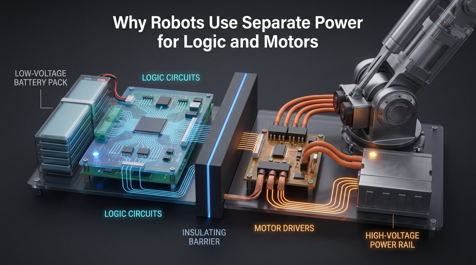
Building a robot that behaves unpredictably is frustrating, especially when the motors seem to cause the brain to glitch. If your Arduino keeps resetting the moment your DC motors spin up, or your sensor readings go haywire during movement, you are likely running into a power isolation problem. Understanding why robots use separate power for logic and motors is one of the most important fundamentals in robotics engineering.
The short answer is that motors and logic circuits have completely different electrical needs. Motors demand high current at higher voltages and generate significant electrical noise, while microcontrollers and sensors need clean, stable, low-voltage power. Sharing a single power supply between them creates voltage drops, electromagnetic interference, and unpredictable resets that can damage components or ruin your project.
In this guide, our team breaks down every reason behind power separation in robotics. We will cover EMI, inrush current, voltage mismatches, motor driver isolation, common ground wiring, and real troubleshooting steps that robotics builders discuss in forums every day. Whether you are wiring your first Arduino robot or designing a professional mobile platform, these principles apply directly to your build.
Table of Contents
Why Robots Use Separate Power for Logic and Motors
Robots use separate power for logic and motors because motors are inductive loads that generate voltage spikes, draw massive startup current, and produce electromagnetic interference. Logic circuits like microcontrollers and sensors require clean, stable voltage to function correctly. When both share a single power source, motor activity corrupts the logic supply, causing resets, data errors, and potential hardware damage.
Think of it this way. Your microcontroller is like a person trying to read a book in a quiet library. Your motors are a rock concert happening in the same room. No matter how good your voltage regulator is, the noise and power swings from the motors will disrupt the delicate work happening on the logic side.
Separating these two power domains solves the problem at its root. The motor supply can dip, surge, and generate all the noise it wants without affecting the clean power feeding your microcontroller, sensors, and communication chips.
The EMI Problem: How Motors Disrupt Logic Circuits
Electric motors are inductive devices, meaning they store energy in magnetic fields. When a motor spins, it generates electromagnetic interference (EMI) that radiates through both the air and the power wires connected to it. This interference travels back along the power lines and can reach your microcontroller if the two share any part of the power chain.
Every time a motor starts, stops, or changes direction, the collapsing magnetic field inside it produces a voltage spike known as a flyback or back-EMF pulse. These spikes can reach tens or even hundreds of volts for brief microseconds. A microcontroller rated for 5V or 3.3V has no tolerance for these transients.
The result of EMI contamination is unpredictable. Sometimes your analog sensor readings jitter or jump to meaningless values. Other times the microcontroller skips instructions or freezes entirely. In worst cases, the voltage spike physically damages the silicon inside your chip.
This is why experienced robot builders treat electrical noise from motors as a primary design concern. A flyback diode placed across each motor absorbs these spikes at the source. Decoupling capacitors on logic power lines filter out high-frequency noise that slips through. But these components only reduce the problem. True isolation requires separate power supplies.
Forum discussions on Pololu and Parallax communities consistently confirm that EMI is the number one cause of flaky robot behavior. Builders report that sensors work perfectly when motors are off but produce garbage data the instant motors engage. Separate power supplies eliminate this issue almost entirely.
Voltage and Current: Two Very Different Worlds
Logic circuits and motors operate at fundamentally different voltage and current levels. A typical microcontroller like an Arduino Uno runs on 5V and draws maybe 50 milliamps. An ESP32 uses 3.3V at even less. Sensors, displays, and communication modules add a few hundred milliamps at most.
Motors live in a completely different electrical world. A standard DC hobby motor might need 6V to 12V and draw 200 to 500 milliamps under normal load. Under heavy load or stall conditions, that same motor can pull 1 to 3 amps. Stepper motors and larger DC motors often demand 12V to 24V at several amps continuously.
Trying to serve both of these loads from a single supply creates an impossible compromise. If you choose a voltage suitable for motors, you need heavy regulation to step it down for logic. If you pick a logic-friendly voltage, your motors will be underpowered and sluggish.
This mismatch is exactly why separate supplies exist. A dedicated motor battery or regulator delivers the right voltage and current headroom for the motors. A separate logic supply delivers clean, regulated 3.3V or 5V for sensitive electronics. Each side gets exactly what it needs without compromise.
Voltage regulation also works more efficiently when each regulator handles only one type of load. Trying to regulate a noisy, fluctuating motor supply down to a stable logic voltage is far harder than regulating a clean dedicated source.
Inrush Current: The Startup Spike That Resets Everything
Inrush current is the surge of electricity a motor draws the instant it starts from a dead stop. A stationary motor has no back-EMF to oppose the incoming current, so for a brief moment it acts almost like a short circuit. This startup draw can be 5 to 10 times the normal running current.
Consider a DC motor that draws 300 milliamps while spinning. At startup, that same motor might pull 2 to 3 amps for a fraction of a second. If this motor shares a power supply with your microcontroller, that sudden current spike drags the supply voltage down hard.
When the supply voltage drops below the microcontroller’s minimum operating threshold, a brown-out reset occurs. The chip shuts down and restarts. From the outside, your robot appears to freeze, reboot, or behave erratically every time the motors kick in.
This is one of the most commonly reported problems in robotics forums. Builders on Reddit and Stack Exchange describe their Arduino resetting the instant motors start, losing all program state and sensor calibration. The fix is almost always the same. Give the motors their own power supply with enough current capacity to handle inrush spikes without sagging.
A properly sized motor supply absorbs the inrush spike without voltage drop. The logic supply remains untouched because it is completely independent. Your microcontroller never sees the disturbance and continues running without interruption.
Motor Driver Isolation: The Buffer Between Two Worlds
A motor driver is the component that sits between your logic circuit and your motors. Devices like the L298N, TB6612FNG, or DRV8833 accept low-power control signals from the microcontroller and use them to switch high-power current to the motors. This is where the two power domains meet.
Most motor driver ICs and H-bridge modules have separate power input pins for exactly this reason. You will typically find a motor power input (often labeled VCC, VMOT, or VMS) and a logic power input (labeled VDD or VLogic). The motor pin connects to your high-current motor supply. The logic pin connects to your clean 5V or 3.3V source.
An H-bridge works by using logic-level signals to control switches (usually MOSFETs) that handle motor current. The MOSFETs are driven by the logic supply, but they switch the motor supply. This means the high-current motor path stays electrically separate from the sensitive control path inside the driver chip.
Optical isolation takes this concept further. Optocouplers use light to transfer control signals across an air gap, meaning there is zero electrical connection between logic and motor sides. This is common in industrial robotics and high-voltage motor control where EMI is severe.
Even with a good motor driver, you still need separate supplies. The driver isolates the control signals, but if the motor and logic share a battery, the voltage sag and noise still propagate through the shared connection.
Common Ground Connections Done Right
One of the most confusing aspects of power separation is the ground question. If the motor and logic circuits use separate power supplies, should their grounds also be separate? The answer is no. The grounds must be connected, but only at one carefully chosen point.
This is called a star ground or single-point ground configuration. All ground wires from the motor supply, logic supply, motor driver, microcontroller, and sensors meet at a single physical node. This ensures every component shares the same voltage reference without creating ground loops.
A common mistake is leaving the grounds disconnected, thinking this completes the isolation. Without a shared ground reference, your control signals from the microcontroller to the motor driver have no return path. The driver cannot interpret the signals correctly, and your motors will not respond.
Another mistake is connecting grounds at multiple points throughout the robot. This creates ground loops where motor current flows back through the logic ground wiring. The resistance in those thin ground traces causes small voltage drops that appear as noise on your logic signals.
The best practice is to run a thick, dedicated ground wire from the motor supply to a single common ground point, then connect the logic ground to that same point. Keep motor current paths short and thick, and logic ground connections clean and separate until they reach the star point.
How to Implement Power Separation in Your Robot
Implementing power separation is straightforward once you understand the principles. Here is a practical approach you can follow for any robot project.
Step 1: Choose your power sources. Use one battery or regulator for motors and another for logic. For small robots, two separate battery packs work well. For larger builds, a single high-capacity battery with two independent switching regulators (one for motors, one for logic) is effective.
Step 2: Size the motor supply for peak current. Calculate the stall current of every motor, add them together, and add a 50 percent safety margin. If two motors each stall at 2 amps, your motor supply should handle at least 6 amps continuously.
Step 3: Add a flyback diode across each motor. A Schottky diode like the 1N5817 placed reverse-biased across the motor terminals absorbs flyback voltage spikes. This protects the motor driver and reduces EMI on the motor power lines.
Step 4: Install decoupling capacitors on logic lines. Place a 0.1 microfarad ceramic capacitor close to the power pins of each IC. Add a larger 10 to 100 microfarad electrolytic capacitor near the voltage regulator input. These filter out high-frequency noise and smooth voltage dips.
Step 5: Wire the common ground as a star point. Connect all grounds at one physical node. Use thick wires for motor current returns and keep them separate from logic ground wires until they reach the star point.
Step 6: Use a motor driver with separate logic and motor power inputs. Connect VLogic to your 5V or 3.3V supply and VMOT to your motor supply. This lets the driver do its job of isolating the two domains internally.
Step 7: Test under load. Run the motors at full speed and under stall conditions while monitoring the logic supply voltage with a multimeter or oscilloscope. The logic voltage should remain rock-steady regardless of what the motors do.
Troubleshooting Power Separation Problems
Even with careful planning, power issues can surface. Here are the most common problems robotics builders encounter and how to fix them.
Problem: Microcontroller resets when motors start. This is the classic symptom of inrush current sagging a shared power supply. The fix is to give motors a separate supply sized for peak stall current. If separation is already in place, check that the motor supply has adequate current capacity and that ground connections are solid.
Problem: Sensor readings are noisy or jump randomly. EMI from motors is coupling into sensor signal wires or the analog-to-digital converter reference. Keep sensor wires short and away from motor wires. Use shielded cables for sensitive analog signals. Add a decoupling capacitor across the sensor power pins.
Problem: Motors run but behave erratically. The motor driver may not be receiving clean control signals because the ground reference is unstable. Verify that all grounds meet at a single star point. Check that the motor driver has separate logic and motor power connected to the correct supplies.
Problem: Robot works on the bench but fails on the floor. On the bench, motors are unloaded and draw less current. On the floor, the increased load pushes current demand higher, exposing weak power isolation. Always test under realistic load conditions, including stalls and direction changes.
Problem: Voltage regulator overheats. If you are stepping down a high motor voltage to logic levels through a linear regulator, the voltage drop times the current equals heat. A switching buck converter is far more efficient and runs cooler. Linear regulators like the 7805 are fine for very low current logic but struggle with any meaningful load.
Community experience from robotics forums reinforces these solutions. Builders on Pololu, Parallax, Reddit, and Stack Exchange consistently report that moving to separate power supplies resolves 90 percent of reliability problems in custom robots. The remaining issues usually trace back to ground wiring or insufficient current capacity.
FAQ
Can I use the same power supply for motors and Arduino?
You can, but it is not recommended for any robot with motors drawing meaningful current. A shared supply risks voltage sags, EMI noise, and brown-out resets. If you must share a supply, use a high-capacity battery, a separate voltage regulator for the Arduino, and heavy decoupling capacitors. Separate supplies are always the safer and more reliable choice.
Why do my motors cause my microcontroller to reset?
Motor startup draws a large inrush current that can be 5 to 10 times the normal running current. If the motor and microcontroller share a power supply, this surge drags the voltage below the microcontroller operating threshold, triggering a brown-out reset. Moving the motors to a separate power supply with adequate current capacity fixes this.
What are the three main types of power used in robotics?
The three main power types in robotics are logic power (3.3V to 5V for microcontrollers and sensors), motor power (6V to 24V or higher for actuators), and communication power (typically 5V or 3.3V for interfaces like I2C, SPI, and UART). Each type has different voltage, current, and noise tolerance requirements.
Do robots use AC or DC power?
Almost all mobile robots use DC power from batteries because DC is portable, safe at low voltages, and compatible with DC motors and electronic circuits. Industrial robotic arms sometimes run on AC power from wall outlets but convert it to DC internally for their motors and control electronics.
How do I prevent electrical noise from motors?
Use separate power supplies for motors and logic, add flyback diodes across motor terminals, install decoupling capacitors on power lines, keep signal wires away from motor wires, use shielded cables for sensitive signals, and connect all grounds at a single star point. These steps combined reduce EMI to negligible levels.
Wrapping Up
Understanding why robots use separate power for logic and motors comes down to three core facts. Motors generate EMI and voltage spikes that corrupt sensitive electronics. Motors need higher voltage and far more current than logic circuits can tolerate. And motor startup inrush current causes voltage sags that reset microcontrollers. Separate power supplies solve all three problems at once.
If your robot is acting up, power isolation is the first thing to check. Split your motor and logic supplies, wire a clean star ground, add flyback diodes and decoupling capacitors, and test under realistic load. These steps will make your robot dramatically more reliable and save you hours of debugging.