
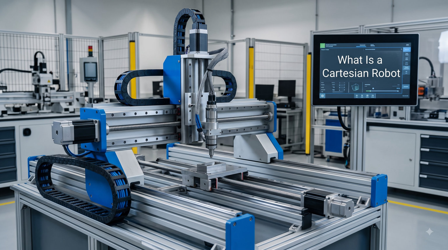
A Cartesian robot is an industrial robot whose three principal axes of control are linear and sit at right angles to each other. Also called a linear robot, it moves along the X, Y, and Z directions of the standard Cartesian coordinate system using prismatic joints. This simple geometry is exactly why Cartesian robots show up in 3D printers, CNC machines, pick-and-place cells, and lab automation worldwide.
I have spent the last decade writing about industrial automation, and the Cartesian robot keeps coming back as the workhorse nobody puts on a magazine cover. In this guide, I will walk you through what a Cartesian robot is, how the axes work, how it compares to gantry, SCARA, and 6-axis robots, where these systems shine, and the practical questions I see on robotics forums about building one yourself.
Table of Contents
What Is a Cartesian Robot? Definition and Key Characteristics
The ISO 8373 standard defines a Cartesian robot as an industrial robot whose arms have three prismatic joints, with axes that are coincident with a Cartesian coordinate system. In plain language, the end effector moves only in straight lines, and those straight lines are perfectly perpendicular to each other. There is no rotation in the primary positioning axes. That single design choice is what defines a Cartesian robot and separates it from every other industrial robot type.
Here are the key characteristics that make a Cartesian robot recognizable on sight:
Three linear axes: X (left-right), Y (forward-back), and Z (up-down) form the core positioning system.
Prismatic joints only: Each axis slides on a linear guide, driven by a belt, ball screw, lead screw, rack and pinion, or linear motor.
Rectangular work envelope: The reachable space is a box defined by the stroke of each axis, not a sphere or cylinder.
Decoupled kinematics: Because each axis is independent, you can command X, Y, and Z positions without solving a complex inverse kinematics problem.
Rigid structure: The frame typically carries moment loads well, especially in gantry-style builds.
Simple motion controller: A standard PLC or dedicated motion controller can drive all three axes, often at lower cost than a 6-axis robot controller.
One thing I want to stress early: the term “Cartesian” describes the geometry, not the size or the brand. A 200 mm desktop pen plotter and a 20-ft factory gantry both qualify, because both move linearly along three perpendicular axes.
How Does a Cartesian Robot Work? The X, Y, and Z Axes Explained
A Cartesian robot works by coordinating three linear actuators along the X, Y, and Z axes. Each axis has its own motor, drive mechanism, and feedback device, and a central motion controller synchronizes them so the end effector reaches the commanded point in space. Picture a rectangular box with one sliding beam on each face, and the tool sits where all three beams meet.
The most common actuator choices are:
Belt drives: Fast and inexpensive, ideal for 3D printers and pick-and-place where accuracy demands are moderate.
Ball screws: Higher accuracy and repeatability, the standard for CNC machines and precision assembly.
Lead screws: Slower but cheaper and self-locking, often used in lab equipment and educational builds.
Linear motors: The highest speed and accuracy, used in semiconductor and electronics manufacturing where every micron counts.
Rack and pinion: Handles long strokes and heavy payloads, common in large gantry systems.
Each axis reports its real position back to the controller through an encoder, often with a linear scale for added precision. The controller compares commanded position to actual position and closes the loop. When you command (X=120, Y=45, Z=10), the controller drives each axis until all three targets are met simultaneously. This is why Cartesian robots are popular for hobbyists: the control math is genuinely simple, and the same firmware that runs a 3D printer can be retuned for a pick-and-place head.
The “degrees of freedom” for a basic Cartesian robot is 3 (XYZ). Many real systems add a fourth DOF by mounting a rotary axis on the Z carriage for screwdriving, or a wrist rotation for part alignment. The core positioning axes stay linear; the extra DOF just sits on top.
Cartesian vs Gantry vs XY Table vs SCARA: Robot Type Comparison
Every newcomer to industrial automation asks the same question I did: how is a Cartesian robot different from a gantry, an XY table, or a SCARA? The short answer is that the four systems share the Cartesian coordinate system but differ in how the axes are mounted and supported. Below is the comparison I use whenever our team evaluates a new automation project.
Cartesian robot: Three perpendicular linear axes. The Z axis is typically cantilevered out from a Y beam that is itself mounted on an X base. Compact footprint, but the Z axis can deflect under heavy moment loads.
Gantry robot: A Cartesian robot where the X axis is supported at both ends, like a bridge or overhead crane. The moving bridge spans the entire work area, so the Z carriage hangs from a rigid structure with no cantilevered moment. Best for large work envelopes and heavy payloads.
XY table: Usually just two axes (X and Y) with no Z. Common in microscopy, inspection, and light assembly. It is technically a Cartesian system, but the industry uses a separate name because it is a building block rather than a full robot.
SCARA robot: Two parallel rotary joints for the X-Y plane plus a linear Z axis. Faster than a Cartesian robot for top-down pick-and-place, but limited to a circular work area and trickier to integrate.
6-axis articulated robot: All rotary joints, full spherical work envelope. The right choice for complex paths, welding, or painting, but overkill (and overpriced) for simple straight-line moves. Modern developments like whole-body control in humanoid robots are pushing the boundaries of what articulated arms can achieve.
If you are choosing between these, the rule of thumb I share with engineers is simple: pick Cartesian when your moves are straight, your work area is rectangular, and your budget favors simplicity. Pick gantry when you need a long stroke with high rigidity. Pick SCARA when you need fast top-down assembly. Pick 6-axis only when you genuinely need articulated reach.
Common Cartesian Robot Applications and Industry Examples
Cartesian robots are everywhere once you start looking. Any application that needs straight-line motion over a rectangular area is a candidate, and the list below covers the most common examples our team sees in factories, labs, and home workshops.
3D printing: The most familiar Cartesian robot to most people. Print beds move on X and Y, and the extruder moves on Z. Creality, Prusa, and Voron all use Cartesian geometry.
CNC machining: CNC routers, mills, and plasma cutters are Cartesian robots with a cutting tool instead of a gripper. The same X, Y, Z setup drives the spindle.
Pick-and-place: Surface-mount technology (SMT) machines use Cartesian robots to place components on circuit boards at thousands of parts per hour.
Laboratory automation: Liquid handling robots, plate stackers, and pipetting systems use Cartesian designs because labware is laid out in a rectangular grid.
Assembly automation: Screwdriving, dispensing, soldering, and gluing stations favor Cartesian robots for their repeatability and easy programming.
Packaging: Carton erecting, filling, sealing, and palletizing lines often use a Cartesian robot for the X-Y traverse and a separate Z stroke for vertical motion.
Material handling: Long-stroke gantries shuttle parts between workstations, especially in automotive and electronics plants. Emerging applications include AI-driven social intelligence for robot fleet management.
A real example: the Festo EXCM Cartesian handling system is a 3-axis Cartesian robot designed for small parts assembly in clean factory cells. It shows the classic layout: one X axis along the base, a Y bridge riding on the X, and a Z module carrying the gripper on the Y. That same layout, scaled up, runs many of the world’s packaging lines.
Cartesian Robot Construction Types: Configurations and Joint Topology
Underneath the surface, Cartesian robots are usually described by how the joints are stacked and supported. The two most common terms I see in technical literature are “serial manipulator” and “parallel manipulator,” and the choice between them affects rigidity, accuracy, and cost.
A serial Cartesian robot stacks the axes one on top of the other: the X base carries the Y carriage, which carries the Z carriage, which carries the tool. Each axis adds its own mass to the next axis above it, and the moving mass is highest. Most 3D printers and pick-and-place machines use this topology because it is simple to design and easy to scale.
A parallel Cartesian robot (sometimes called a H-frame or parallel-kinematic machine) drives the X-Y plane with two synchronized motors on either side of a moving carriage. This cancels out the moment load on the X axis, increases stiffness, and improves accuracy. The trade-off is a more complex control system and a smaller usable work area. Delta robots, despite looking different, share this parallel philosophy for the X-Y plane.
There are also 2-axis, 3-axis, and 4-axis variants. A 2-axis XY table has no vertical motion, while a 4-axis Cartesian adds a rotary wrist for tool rotation. The core geometry stays Cartesian, no matter how many DOF you stack on top.
You will also see the term cantilevered Cartesian robot in product literature. That simply means the Z axis hangs off one side of the Y beam rather than being supported on both sides. Cantilevered designs are compact and cheap, but they deflect more under load, so they are best suited to lighter payloads and shorter strokes.
Building a DIY Cartesian Robot: What Our Team Learned
This is the section competitors skip, and it is the one I get asked about most on the Smashing Robotics forum threads and on Reddit’s r/robotics community. A surprising number of readers want to know how to build a Cartesian robot for learning, and the honest answer is that it is one of the best projects a beginner can take on, because the control math is approachable and the parts are widely available.
Here is the path I recommend if you want to build your own:
Start with a 3D printer kit. A Cartesian 3D printer is a fully functional 3-axis Cartesian robot. Tuning the firmware teaches you coordinate systems, microstepping, and PID control without any extra cost.
Add a gripper and a small conveyor. Swap the hot end for a suction gripper or a servo jaw, and your printer is now a pick-and-place machine. Marlin and Klipper firmware both support this with minor tweaks.
Scale up the frame. Move to 2020 or 4040 aluminum extrusion, add a longer ball screw for the X axis, and you have a desktop Cartesian robot with a 300 mm to 500 mm work envelope. This is the size most forum users build first.
Consider a gantry frame for long strokes. If you need a 2 m or 3 m stroke, build a gantry-style Cartesian robot with the X axis supported on both ends. Use rack-and-pinion or a long ball screw, and watch for deflection in the bridge.
Pick the right drivetrain. For a 20-ft Cartesian robot, a rack-and-pinion drive or a belt drive with steel-reinforced timing belts will outperform lead screws. Forum users have repeatedly flagged deflection as the #1 issue with overly long screw-driven designs.
For sourcing, the desktop-scale brands I see mentioned most often on r/robotics are OpenBuilds, V-Slot, and IGUS drylin. For motion controllers, the popular choices are Arduino with GRBL, the Duet 3, the Smoothieboard, and LinuxCNC for larger builds. None of these are magic; they all work, and the community will help you debug if you share your build log.
When to Choose a Cartesian Robot: Advantages and Limitations
A Cartesian robot is the right answer when your application matches its strengths. Here is the honest list of advantages and limitations I walk clients through before they buy.
Advantages:
Positioning accuracy of 0.01 mm to 0.05 mm is achievable with ball screws, far better than most SCARA systems.
Repeatability is excellent because each axis is mechanically simple and closed-loop controlled.
The rectangular work envelope is efficient for conveyor-fed parts, labware grids, and printed circuit boards.
Control is straightforward, so a small team can program and maintain it without a robot specialist. For teams scaling up deployment, warehouse robot fleet safety and scaling best practices are essential reading.
Cost per millimeter of stroke is lower than articulated or SCARA robots.
Limitations:
Cantilevered Z axes deflect under heavy moment loads, so large-offset payloads need a gantry frame.
No rotational reach, so complex 3D paths require an external rotary axis or a different robot type.
Footprint is larger than a SCARA or 6-axis robot for the same usable work envelope, because the axes occupy their full stroke.
Custom integration is needed for unusual work envelopes, which is more work than buying a pre-engineered 6-axis cell.
If your parts move in straight lines, your work area is rectangular, and you need repeatable accuracy on a budget, a Cartesian robot will almost always beat more complex designs on cost and simplicity. If your parts need to be tilted, rotated, or approached from multiple angles, look at SCARA or articulated robots instead.
Frequently Asked Questions
What are the four types of robots?
The four most common types of industrial robots are Cartesian (linear XYZ), cylindrical (one rotary and two linear axes), spherical/polar (two rotary and one linear), and articulated (all rotary joints, including the popular 6-axis arm). SCARA is sometimes listed as a fifth category for selective compliance assembly.
Can you provide an example of a Cartesian robot?
A 3D printer is a familiar example of a Cartesian robot. The print bed moves along the X and Y axes while the extruder moves up and down on Z. Industrial examples include the Festo EXCM handling system, SMT pick-and-place machines for circuit boards, and CNC routers used in woodworking and metal cutting.
What is a Cartesian?
Cartesian refers to the Cartesian coordinate system, named after René Descartes, which uses three perpendicular axes labeled X, Y, and Z to define any point in 3D space. In robotics, a Cartesian system moves only along these three straight, mutually perpendicular lines.
What are Cartesian coordinate robots?
Cartesian coordinate robots are industrial robots whose three principal axes of control are linear and meet at right angles. They use prismatic joints to slide along the X, Y, and Z directions and form a rectangular work envelope. They are also called linear robots and are widely used in 3D printing, CNC machining, and pick-and-place automation.
Conclusion
A Cartesian robot is the simplest industrial robot you can buy, build, or program, and that is precisely why it has become the workhorse of modern automation. Three perpendicular linear axes, prismatic joints, and a rectangular work envelope give you high accuracy, easy control, and a price that small shops can afford.
If you are still learning the basics, start with a Cartesian 3D printer or a desktop pick-and-place build, and you will master the same geometry that runs factory cells worldwide. For more on related automation topics, our team has covered how planetary gearboxes work in robot joints and robots that learn on the job. Once you understand what a Cartesian robot is, you can decide if it is the right pick for your next project.