
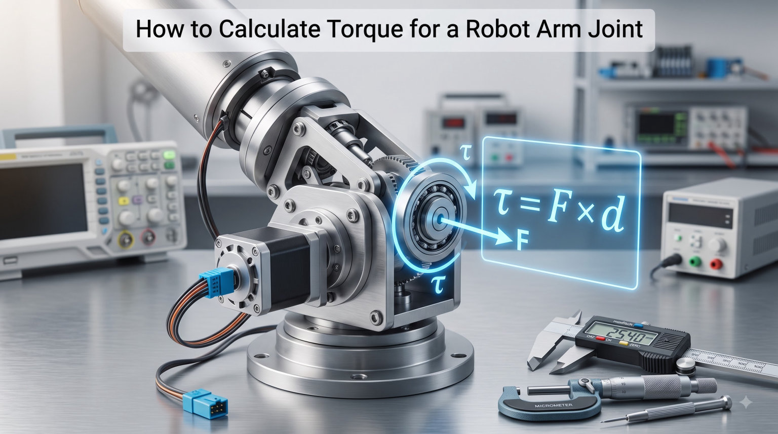
Every robot arm joint lives or dies by one number: torque. Get the calculation right, and your arm moves smoothly, lifts its payload, and runs for years without burning out a motor. Get it wrong, and you end up with a stalled joint, a smoking servo, or an arm that collapses under its own weight.
In this guide, I will walk you through exactly how to calculate torque for a robot arm joint from scratch. We will cover the core formula, break down static versus dynamic torque, work through a real calculation with actual numbers, and tackle the common mistakes that trip up builders at every level.
Whether you are building a small hobby arm with a 500-gram payload or designing a multi-DOF industrial arm, the math is the same. The difference is in how carefully you apply it. Let us get into it.
Table of Contents
What Is Torque in a Robot Arm?
Torque is the rotational equivalent of linear force. When you push a box in a straight line, you apply force measured in Newtons. When you rotate a joint, you apply torque measured in Newton-meters (Nm).
Think of torque as the “twisting power” a motor needs to produce at a joint. Every weight hanging off that joint creates a gravitational moment that tries to pull the arm downward. The motor must generate enough torque to fight that pull and hold the arm in position.
In a robot arm, torque at any given joint comes from every weight downstream of that joint. That includes the payload at the end, the motors on the next segments, the arm links themselves, and even the wiring and connectors. All of these contribute to the total load the joint motor must overcome.
This is why understanding robot arm torque is not optional. It is the single most important calculation you do before buying a single motor.
The Basic Torque Formula
The fundamental formula for torque is straightforward: torque equals force multiplied by the perpendicular distance from the pivot point.
τ = F × r × sin(θ)
Here is what each variable means:
τ (tau): Torque, measured in Newton-meters (Nm). This is the output you need from your motor.
F: Force, measured in Newtons (N). This is the weight of the load. Convert kilograms to Newtons by multiplying by 9.81 (acceleration due to gravity).
r: Distance from the joint axis to the point where the force is applied, measured in meters. This is also called the lever arm or moment arm.
θ (theta): Angle between the arm and the direction of the force (gravity), measured in degrees or radians.
The sin(θ) part is where many people get tripped up. When the arm is fully extended horizontally, the angle is 90 degrees, sin(90) equals 1, and you get maximum torque. When the arm hangs straight down, the angle is 0 degrees, sin(0) equals 0, and the torque requirement drops to nearly zero.
This angle dependence matters because a robot arm rarely holds a single position. You size your motor for the worst-case angle, which is almost always when the arm is fully extended horizontally.
Understanding Moment Arm and Lever Arm
The moment arm is the perpendicular distance from the axis of rotation to the line of action of the force. In simpler terms, it is how far the weight sits from the joint pivot, measured at a right angle to the direction gravity pulls.
For a robot arm holding a weight straight out horizontally, the moment arm equals the full length of the arm from the joint to the payload. The weight pulls straight down, and the arm extends straight out, so the perpendicular distance is simply the arm length.
But when the arm tilts upward at an angle, the perpendicular distance shrinks. This is exactly what the sin(θ) term in the formula captures. A 1-meter arm tilted 30 degrees above horizontal has an effective moment arm of only 0.5 meters (1 × sin(30) = 0.5).
One critical detail from forum discussions: always measure the moment arm from the joint axis, not from the edge of the motor housing or the base plate. I have seen builders measure from the wrong point and end up with numbers that are off by 20% or more.
For links that have their own weight (not just a point payload at the end), you measure the moment arm to the center of mass of that link, not to its tip. This is a common source of error I will address in the mistakes section.
Static Torque vs. Dynamic Torque
Static torque is the torque required to hold the arm stationary in a given position against gravity. Dynamic torque is the additional torque needed to accelerate or decelerate the arm from one position to another.
Most beginner calculations focus only on static torque, and for good reason. Static torque is usually the larger of the two in low-speed applications, and it represents the minimum your motor must handle continuously. If your motor cannot produce enough static torque, the arm will not even hold position, let alone move.
Dynamic torque adds the requirement of overcoming inertia. When you command a joint to accelerate, the motor must produce extra torque beyond what gravity demands. The formula for the dynamic component is:
τ_dynamic = I × α
Where I is the moment of inertia of the arm and payload (measured in kg·m²) and α is the angular acceleration (measured in radians per second squared). The faster you want the arm to move, the higher the dynamic torque requirement.
Total torque at any instant is the sum of both: τ_total = τ_static + τ_dynamic. For arms that move slowly, dynamic torque might add only 10-20% to your static requirement. For fast pick-and-place arms, dynamic torque can double or triple the total.
Here is a quick comparison to keep the two straight:
Static torque: Holds position against gravity. Depends on weight, arm length, and joint angle. Present whenever the arm is powered on.
Dynamic torque: Accelerates and decelerates the arm. Depends on moment of inertia and angular acceleration. Present only during motion.
Worst case: Static torque at full horizontal extension plus dynamic torque at peak acceleration. Size your motor for this scenario.
Step-by-Step: How to Calculate Torque for a Robot Arm Joint
Here is the exact procedure I use to calculate torque for a robot arm joint. Follow these steps in order, and you will get reliable numbers every time.
Step 1: Identify all weights downstream of the joint. List every mass that the joint must support. This includes the payload, the arm link beyond the joint, any motors mounted further out, grippers, and even significant cable runs. Write down each weight in kilograms.
Step 2: Convert weights to forces. Multiply each mass by 9.81 to get the force in Newtons. A 2 kg payload exerts 19.62 N of force due to gravity.
Step 3: Find the center of mass for each weight. For point loads like a payload or a motor, the center of mass is at the object itself. For arm links, measure to the geometric center of the link. A 40 cm link has its center of mass at the 20 cm mark.
Step 4: Measure the distance from the joint axis to each center of mass. This is your moment arm (r) for each weight, measured in meters. Record each one.
Step 5: Determine the worst-case angle. For static torque, the worst case is when the arm extends fully horizontally (theta = 90 degrees, sin(90) = 1). Use this angle for your primary calculation.
Step 6: Calculate static torque for each weight. Apply the formula τ = F × r × sin(θ) to each individual weight. For the horizontal worst case, this simplifies to τ = F × r since sin(90) = 1.
Step 7: Sum all torques. Add up the individual torque values. This total is the static torque the joint motor must produce to hold the arm in the worst-case position.
Step 8: Add dynamic torque if applicable. If the arm moves, estimate the moment of inertia and angular acceleration, then add τ_dynamic = I × α to your total.
Step 9: Apply a safety factor. Multiply your final torque by 2 to 3 to account for friction, inefficiencies, wear, and unexpected loads. I will explain safety factors in detail below.
Step 10: Compare against motor specs. Check that your chosen motor’s continuous torque rating meets or exceeds your calculated value (with safety factor applied).
Worked Example: Calculating Torque for a 2-Link Robot Arm
Let us run through a complete calculation with real numbers so you can see the process end to end. We will calculate the torque for the base joint (Joint 1) of a simple 2-link arm.
The setup: The arm has two aluminum links. Link 1 is 30 cm long and weighs 0.5 kg. Link 2 is 25 cm long and weighs 0.4 kg. The arm carries a 1.5 kg payload at the end. There is a motor at Joint 2 weighing 0.3 kg.
Joint 1 must support everything: Link 1, Link 2, the Joint 2 motor, and the payload. Let us calculate each contribution with the arm fully extended horizontally.
Payload contribution: Force = 1.5 kg × 9.81 = 14.72 N. Distance from Joint 1 = 0.30 + 0.25 = 0.55 m. Torque = 14.72 × 0.55 = 8.10 Nm.
Link 2 contribution: Force = 0.4 kg × 9.81 = 3.92 N. Center of mass is at midpoint of Link 2, so distance from Joint 1 = 0.30 + 0.125 = 0.425 m. Torque = 3.92 × 0.425 = 1.67 Nm.
Joint 2 motor contribution: Force = 0.3 kg × 9.81 = 2.94 N. Distance from Joint 1 = 0.30 m. Torque = 2.94 × 0.30 = 0.88 Nm.
Link 1 contribution: Force = 0.5 kg × 9.81 = 4.91 N. Center of mass at midpoint of Link 1, distance from Joint 1 = 0.15 m. Torque = 4.91 × 0.15 = 0.74 Nm.
Total static torque at Joint 1: 8.10 + 1.67 + 0.88 + 0.74 = 11.39 Nm.
With a safety factor of 2.5, the motor at Joint 1 needs a continuous torque rating of at least 11.39 × 2.5 = 28.5 Nm. That is a substantial motor, which makes sense. The base joint of any robot arm always carries the heaviest load because it supports everything above it.
Notice how the payload alone accounts for 71% of the total torque at Joint 1. This is why extending the arm length or adding payload weight has such a dramatic effect on base joint requirements.
How to Calculate Torque for Multi-Joint Arms
Multi-joint arms follow the same principle, but each joint sees a different load. The key rule: each joint must support all weight downstream of it, but downstream weights only contribute to upstream joints.
Joint 1 (the base) supports the most weight because everything is downstream of it. Joint 2 supports Link 2, the Joint 3 motor, and the payload, but not Link 1. Joint 3 supports only the payload and the gripper.
To calculate torque for a multi-joint arm, work from the outermost joint inward. Start at the end effector and calculate the torque at the last joint. Then move to the next joint inward, adding the previous joint’s motor and link to the load list. Continue until you reach the base.
Here is the workflow for a 3-DOF arm: First, calculate Joint 3 torque (payload and gripper only). Second, calculate Joint 2 torque (Link 3, Joint 3 motor, payload). Third, calculate Joint 1 torque (Link 2, Joint 2 motor, Link 3, Joint 3 motor, payload).
One subtlety: when upper joints are at an angle, the effective moment arm at lower joints changes. A fully detailed calculation uses the cosine of each joint angle to find the horizontal projection of each link. For a first-pass estimate, assume the worst case where all links are horizontal.
Forum users frequently report shock at how high the base joint torque gets for multi-DOF arms. A user on Reddit mentioned needing over 100 Nm for a 5 kg payload arm. Their math was likely correct. Industrial arms with a few kilograms of payload routinely use base motors rated for 50 to 200 Nm of continuous torque.
Safety Factors: Why You Need 2 to 3 Times Headroom
Apply a safety factor of 2 to 3 times your calculated torque before selecting a motor. This headroom accounts for friction in gearboxes, bearing losses, motor efficiency drops under load, and unexpected forces during operation.
Without a safety factor, a motor that exactly matches your calculated torque will struggle. It will run hot, draw excessive current, and likely fail within weeks or months. The cost difference between a motor rated at your exact torque and one rated 2.5 times higher is usually small compared to the cost of replacing a burned-out motor and fixing the damage it causes.
Use this checklist before finalizing your motor selection:
Did you account for the weight of all links, motors, and the payload?
Did you use the worst-case horizontal angle for static torque?
Did you add dynamic torque if the arm moves at speed?
Did you multiply the final number by at least 2 for the safety factor?
Did you check the motor’s continuous torque rating, not just its peak rating?
Did you factor in the gearbox ratio if using a geared motor?
A 2x safety factor is the bare minimum for hobby projects. For anything that will run daily or carry loads near its rated capacity, use 2.5 to 3x. Industrial applications often use 3x or higher to ensure years of reliable operation.
Common Mistakes When Calculating Robot Arm Torque
Here are the errors I see most frequently, drawn from forum discussions and real builder experiences. Each one can lead to an undersized motor and a failed project.
Mistake 1: Forgetting the weight of the arm links. Many beginners calculate torque using only the payload and ignore the arm itself. For lightweight arms with heavy payloads, this works out. For arms with substantial metal or plastic links, ignoring link weight can underestimate torque by 30% or more.
Mistake 2: Measuring the moment arm to the wrong point. Always measure from the axis of the joint pivot. Measuring from the motor housing edge, the base plate, or any other reference point introduces error. On a robot arm, even a 2 cm measurement error on a 30 cm arm creates a 6% error in your torque number.
Mistake 3: Using peak torque instead of continuous torque. Motor datasheets list both peak (or stall) torque and continuous torque. Peak torque can only be sustained for a few seconds before the motor overheats. Size your selection against the continuous rating, which is what the motor can produce indefinitely without damage.
Mistake 4: Ignoring joint angles in worst-case analysis. Some builders calculate torque at the arm’s resting position (pointing down) and get numbers that look fine. Then the arm extends horizontally and the motor stalls. Always calculate for the fully extended horizontal position.
Mistake 5: Not accounting for downstream motors and grippers. Every motor mounted further out along the arm adds weight that closer joints must support. A 300-gram servo at Joint 2 adds real torque load to Joint 1. List every component when totaling your weights.
Mistake 6: Confusing degrees and radians. The sin(θ) function in calculators and programming languages uses radians by default. If you plug in 90 expecting 90 degrees, the calculator interprets it as 90 radians and gives you the wrong answer. Convert degrees to radians by multiplying by π/180, or set your calculator to degree mode.
Mistake 7: Underestimating torque for multi-joint arms. As we discussed, the base joint carries everything. Builders often size all joints the same, then find the base motor stalling while the wrist motor has power to spare. Calculate each joint separately and size motors accordingly.
Motor Selection Basics: Matching Torque to the Right Servo
Once you have your calculated torque (with safety factor), motor selection becomes a matching exercise. You need a motor whose continuous torque rating meets or exceeds your number.
For small hobby arms, standard servos and stepper motors with gearboxes are common. A NEMA 23 stepper with a 10:1 planetary gearbox can produce 2 to 3 Nm of output torque. For larger arms, brushless DC servo motors with harmonic drives deliver high torque in a compact package.
When comparing motors, check these specifications:
Continuous torque: The torque the motor can produce indefinitely. This is your baseline comparison number.
Peak torque: The maximum burst torque for brief acceleration. Useful but not for sizing.
Gearbox ratio: Divides motor speed and multiplies motor torque. A 50:1 gearbox multiplies torque by roughly 50 (minus efficiency losses).
Gearbox efficiency: Planetary gears run at 90-95% efficiency. Worm gears run at 50-70%. Multiply your torque by the efficiency factor when calculating real output.
Duty cycle: How long the motor can run continuously before needing a cool-down period. Match this to your application’s usage pattern.
If your calculated torque exceeds what a single motor can deliver, you have two options. First, reduce the arm length or payload to lower the torque requirement. Second, use a higher-ratio gearbox, which trades speed for torque. Harmonic drives (strain wave gears) are popular in industrial arms because they offer ratios of 50:1 to 300:1 with near-zero backlash.
For servos specifically, the torque calculation translates directly to the servo’s kg-cm rating. Convert Nm to kg-cm by multiplying by 10.2. So 28.5 Nm equals roughly 290 kg-cm, which is well beyond hobby servo territory and firmly in industrial servo territory.
FAQs
How do you calculate the torque arm?
The torque arm (also called the moment arm or lever arm) is the perpendicular distance from the axis of rotation to the line of action of the force. To find it, measure the straight-line distance from the joint pivot to where the weight acts, then multiply by the sine of the angle between the arm and the vertical direction. For a horizontally extended arm, the torque arm equals the full length from the joint to the load.
What is the formula for calculating torque?
The basic torque formula is tau = F x r x sin(theta), where F is the force in Newtons (mass times 9.81), r is the distance from the pivot to the force in meters, and theta is the angle between the arm and the direction of the force. For a robot arm held horizontally with the load at the end, this simplifies to tau = F x r because sin(90 degrees) equals 1.
How to calculate servo torque?
To calculate servo torque, first determine the total load the servo must lift (payload plus any arm weight downstream of the joint). Convert the load to Newtons, multiply by the distance from the servo axis to the load center of mass in meters, then multiply by a safety factor of 2 to 3. Convert the result from Nm to kg-cm (multiply by 10.2) to match common servo spec sheets.
How to calculate torque with lever arm?
Torque with a lever arm is calculated as tau = F x r, where F is the applied force in Newtons and r is the perpendicular lever arm length in meters. If the lever is at an angle to the force direction, multiply by sin(theta) to account for the reduced effective lever arm. For a robot arm, the lever arm is the distance from the joint to the payload, and the force is the payload weight times gravity.
Why does the base joint need the most torque?
The base joint of a robot arm must support the weight of every component above it, including all arm links, all downstream motors, and the payload. Every additional weight and every additional distance adds to the base joint’s torque requirement. Upper joints support progressively less weight because they only carry what is downstream of them, making the base joint the highest-torque joint by far.
Should I use degrees or radians for torque calculations?
You can use either, but you must be consistent. Most calculators and programming languages use radians by default for trigonometric functions. If you enter 90 expecting degrees but the tool reads radians, you get the wrong answer. Always convert degrees to radians by multiplying by pi divided by 180, or verify that your calculator is in degree mode.
Conclusion
Calculating torque for a robot arm joint comes down to a clear process: identify every weight downstream, find each center of mass, measure the moment arm to each, apply the formula τ = F × r × sin(θ) at the worst-case angle, sum the results, and apply a safety factor of 2 to 3.
The math is not complicated, but the discipline of accounting for every component is what separates arms that work from arms that fail. Start with the static torque calculation, add dynamic torque if your arm moves quickly, and never skip the safety factor.
If you follow the step-by-step process in this guide and avoid the common mistakes listed above, you will have reliable torque numbers for every joint. From there, motor selection is simply a matter of matching your calculated torque to a motor’s continuous rating. Build with confidence, and your robot arm will lift what it is supposed to lift.