
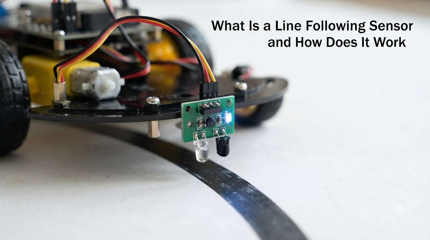
A line following sensor is an infrared (IR) device that uses an emitter and detector pair to detect the reflectance difference between a line (usually black) and the surface (usually white), enabling robots to autonomously follow a predetermined path. I have wired dozens of these sensors to Arduino boards, STM32 boards, and even bare Atmega32 chips over the years, and the same core physics shows up every time.
In this guide, I will break down exactly how a line following sensor works, the different types you will find in hobby and industrial robotics, and how to wire one to a microcontroller. You will also get a step-by-step calibration procedure I use on every build, plus answers to the most common questions I see on robotics forums.
Table of Contents
What Is a Line Following Sensor
A line following sensor is an electronic component that detects the contrast between a dark line and a lighter surface so a robot can steer along that line. In practice, it is a small module containing an infrared LED (the emitter) and a phototransistor or photodiode (the detector), mounted a few millimeters above the floor and pointed downward.
Line following sensors are the eyes of one of the most popular beginner projects in robotics: the line follower robot. They are also the workhorse of industrial automated guided vehicles (AGVs) that zoom through warehouses carrying pallets. Anywhere a controlled path exists on the floor, a line following sensor can read it.
Why does this matter for your projects? Because the same $2 module that teaches a student about reflectance can also anchor a real factory automation cell. Understanding the principle scales from hobby bots to multi-million-dollar logistics fleets.
How Does a Line Following Sensor Work
A line following sensor works by shining infrared light at the floor and measuring how much of that light bounces back. Dark surfaces absorb most of the IR light, while light surfaces reflect most of it, and the sensor turns that reflectance difference into a voltage the microcontroller can read.
The IR Emitter and Photodetector Pair
Every line following sensor contains two key parts facing the floor. The first part is an IR LED that emits infrared light at a wavelength around 940 nm, which is invisible to human eyes but perfect for bouncing off surfaces.
The second part is a photodetector, usually a phototransistor, that changes its conductivity based on how much infrared light hits it. When more reflected IR light reaches the photodetector, it conducts more current; when less light reaches it, it conducts less.
Most modules package the emitter and detector side by side with a small physical wall between them. That wall blocks direct light from the LED from spilling into the detector, so the detector only sees light that has bounced off the floor.
The Reflectance Principle Explained
Reflectance is just the fraction of light a surface sends back to the source. A clean white surface might reflect 80 to 90 percent of incoming IR light, while a matte black surface might reflect only 5 to 10 percent.
That difference is huge, and it is the entire reason a line following sensor works. The line drawn on the floor is almost always black on a white background, so the sensor reading drops sharply when it crosses the line and rises again when it moves off.
Lighting and surface material matter. Glossy surfaces can cause weird reflections, and bright ambient sunlight contains plenty of IR that confuses the detector. That is why serious robots often shield the sensor with a small hood or run the IR LED in a modulated pulse the detector can lock onto.
Converting Reflectance to a Usable Signal
The phototransistor does not output a clean digital 0 or 1 by itself. It changes resistance, and a simple voltage divider circuit turns that resistance change into an analog voltage somewhere between 0 V and the supply voltage (often 5 V or 3.3 V).
That analog voltage is what your microcontroller’s analog pin reads. The analog-to-digital converter (ADC) inside the chip turns the voltage into a number, and from that number your code can decide whether the sensor is over the line or off it.
Many cheap modules also include a comparator chip and a small potentiometer on board. The comparator compares the analog voltage to an adjustable threshold, and the module then outputs a clean digital HIGH or LOW signal. That is what I call a digital-output line following sensor.
Types of Line Following Sensors
Not all line following sensors are built the same. The two most useful distinctions for your build are the output type (analog versus digital) and the number of sensors in the array (single sensor versus multi-sensor strip).
Analog vs Digital Output Sensors
An analog-output line following sensor sends a continuous voltage to your microcontroller. You read it with an ADC pin and decide your own threshold in software, which gives you much more flexibility for different line colors and lighting conditions.
A digital-output sensor has an onboard comparator that snaps the analog reading to a binary HIGH or LOW based on a threshold you set with a small screw on the potentiometer. These are easier to wire (no ADC pin needed), but you lose the ability to track intermediate reflectance values.
For learning and competition work, I recommend analog sensors. They let you read gradient values, run a weighted average across an array, and detect line crossings more reliably. For simple obstacle-style projects, digital sensors are faster to deploy.
Single Sensor vs Sensor Array Configurations
A single line following sensor can only tell you whether it is over the line or off it. That is enough for very simple tracks, but the moment a line branches, has gaps, or has a sharp 90-degree turn, a single sensor cannot pick a direction.
A sensor array is a row of sensors, usually 5 to 11, mounted in a line across the front of the robot. The classic 8-sensor array is popular because it can encode the line position as a single byte (one bit per sensor), which makes line detection logic almost trivial.
More sensors cost more money and use more microcontroller pins (or need a multiplexer), but they handle intersections, T-junctions, and acute-angle turns much more reliably. If you plan to run a real competition track, an 8-sensor array is the minimum I would consider.
How Sensors Connect to a Microcontroller
Wiring a line following sensor to a microcontroller is straightforward. You need three wires per sensor: VCC, GND, and the signal wire. VCC is usually 3.3 V or 5 V depending on your module, GND goes to common ground, and the signal wire goes to an analog or digital input pin on your board.
Wiring the Sensor to Arduino or STM32
On an Arduino Uno, an analog line following sensor plugs into any pin marked A0 through A5. You power the sensor from the 5 V pin and read the value with analogRead(pin), which returns a number between 0 and 1023.
On an STM32 board, the process is identical, but the ADC is 12-bit, so the range is 0 to 4095 for better resolution. That extra resolution is genuinely useful for detecting subtle differences between a faded black line and a fresh one.
For a digital sensor, plug the signal wire into any digital input pin and use digitalRead(pin). You will also want to set the onboard threshold potentiometer so the output flips cleanly at the line edge. I usually set the threshold while the sensor is sitting halfway on the line.
Reading Analog and Digital Values
Once wired, a simple Arduino sketch can read the sensor and print the value to the serial monitor. I use this exact test code on every new sensor I buy to make sure it actually works before I commit it to a robot.
If you are building a multi-sensor array, you can either dedicate one analog pin per sensor or use a multiplexer like the CD74HC4067 to read up to 16 sensors through a single pin. For an 8-sensor array, dedicating pins is usually simpler.
When you move from reading one sensor to many, the next step is turning those raw values into a single line position number. That is what an analog-to-digital converter (ADC) is for, and our ADC guide on Smashing Robotics covers the conversion math in detail.
Line Detection Algorithm Basics
The simplest line detection algorithm compares the sensor reading to a fixed threshold. If the reading is below the threshold, the sensor is over the line; if it is above, it is off the line. That binary decision is enough for a one-sensor robot to follow a basic track.
For a sensor array, the standard trick is the weighted average. Multiply each sensor reading by its position index (for example, -4, -3, -2, -1, 0, 1, 2, 3, 4 for a 9-sensor array), sum those products, and divide by the sum of all sensor readings. The result is a single number that tells you where the line is under the array, from full left to full right.
That single number becomes the error signal your control loop uses. Zero means the line is perfectly centered, positive means it has drifted right, and negative means it has drifted left. Your code then turns the wheels to drive the error back toward zero, which is the entire essence of line following.
Most beginners start with a simple if/else algorithm that says “if left sensors see the line, turn left; if right sensors see the line, turn right.” That works for slow robots on smooth tracks. Faster robots and competition tracks need PID control, which I will touch on briefly later.
Calibrating a Line Following Sensor
Calibration is the difference between a line follower that works on your desk and one that works in a hallway. Even cheap IR modules vary from unit to unit, and lighting conditions change throughout the day, so a one-time calibration at the start of every run is non-negotiable.
Why Calibration Matters
The raw analog reading from a line following sensor depends on the supply voltage, the surface reflectivity, the distance to the floor, and even the temperature of the IR LED. A threshold that works in your living room will fail in a sunlit gymnasium.
Worse, the IR LED in cheap modules can heat up after a few minutes of continuous use, which shifts its output wavelength and brightness. That is why forum users often report that their robot “worked five minutes ago but now misses the line.”
The fix is calibration. Spend 30 seconds at the start of every run sampling the sensor over both the line and the background, set your threshold to the midpoint, and store the result in EEPROM if you want to skip the step next time.
The Median-Filter Calibration Technique
For sensor arrays, the median-filter calibration technique is what the serious builders use. Instead of reading each sensor once, you read it 20 to 30 times while moving the robot slowly back and forth across the line. You then sort those readings and pick the median value as your threshold.
The median is more robust than the average because it ignores the wild readings at the very edges of the line transition. A few noisy spikes will not corrupt your threshold the way they would if you used the mean.
After setting the threshold, run a quick test pass: drive the robot forward and check the live sensor readings on a serial plotter. If the line is detected clearly with at least 30 percent margin between the line and background readings, you are good to go. If the readings are too close, recheck the sensor height (around 8 to 15 mm is typical) and the LED current-limiting resistor.
Common Applications of Line Following Sensors
Line following sensors show up in three broad areas: industrial automation, educational robotics, and hobby competitions. The same underlying technology serves all three, but the requirements are very different.
In warehouses and factories, automated guided vehicles (AGVs) follow magnetic tape or painted lines on the floor to move goods between stations. These systems often use 8 or more sensors in an array, plus encoders and PID control, to keep heavy payloads moving smoothly at walking pace.
In schools and universities, line following sensors are the standard first project for a robotics class. They teach the reflectance principle, ADC basics, threshold logic, and motor control in one compact project. The same lesson plan works for Arduino, Raspberry Pi Pico, and STM32 boards.
In hobby competitions, line follower races test how fast a robot can complete a complex track with sharp turns, intersections, and gaps. Top competitors run 8 to 11 sensor arrays with custom PID tuning, and they spend hours on calibration before each event. Powering these robots reliably also means picking the right battery for robot projects, since voltage sag can throw off your calibrated thresholds mid-run.
Troubleshooting Common Line Sensor Issues
Even with a good build, line following sensors can misbehave. Here are the four problems I see most often in the robotics forums, and how I fix them.
Sensor reads the same value everywhere. This usually means the IR LED is dead, the wiring is reversed, or the sensor is too far from the floor. Check the LED with a phone camera (most phone cameras can see IR light as a faint purple glow) and lower the sensor to 10 mm.
Readings drift over time. That is almost always the IR LED heating up. Add a small delay in your code, pulse the LED only when you are taking a reading, or use a lower-current resistor. Some builders even add a heatsink clip.
Robot loses the line on sharp turns. Either the sensor array is too narrow, the robot is moving too fast, or the threshold is wrong. Slow the robot down, widen the array if you can, and recheck the threshold with the median-filter method.
Ambient light causes false readings. Sunlight and fluorescent lights both contain IR. The fix is to modulate the IR LED at a specific frequency (usually 38 kHz, like a TV remote) and add a bandpass filter on the detector. The TCRT5000 with a hardware filter is the classic module for this.
Frequently Asked Questions
Can you explain the concept of a line follower robot?
A line follower robot is a small autonomous vehicle that uses a line following sensor (or an array of them) to detect a dark line on the floor and steer itself along that line. The sensor reads the contrast between the line and the background, the microcontroller turns that reading into a steering decision, and the motor driver applies power to the wheels to keep the robot on track.
What sensors do line-following robots use?
Most line-following robots use infrared (IR) reflectance sensors as the primary detector because they are cheap, fast, and work in most indoor lighting. The most common modules are the TCRT5000 (analog) and the QTR-1A (analog with a clean output stage). For more complex projects, cameras and LiDAR can also be used, but IR reflectance remains the default choice for beginners and competitions.
How to use a line follower?
To use a line follower, mount the line following sensor a few millimeters above the floor, wire it to a microcontroller, and load code that reads the sensor and adjusts motor speed and direction to keep the line centered. Power the robot from a stable battery, calibrate the sensor threshold for the specific line and surface, and test on a simple track before moving to sharp turns or intersections.
Why is my line following sensor not detecting the line?
The most common reasons a line following sensor fails to detect a line are: the sensor is too far from the floor, the threshold is set wrong, the IR LED is dead, ambient light is overpowering the reflected IR, or the line color does not have enough contrast with the surface. Start by checking the sensor height (8 to 15 mm is typical), then recalibrate the threshold, then check the IR LED with a phone camera.
How does a line follower robot with obstacle avoidance work?
A line follower robot with obstacle avoidance adds a second sensing system, usually an ultrasonic sensor or a time-of-flight (ToF) laser sensor, mounted on the front or top of the robot. The microcontroller reads the line following sensor for steering and the obstacle sensor for forward clearance; when an obstacle is detected within a set distance, the robot stops, scans for a clear path, and then resumes line following.
Conclusion
A line following sensor is one of the simplest and most useful sensors in robotics, and it works on a single physical principle: IR light reflects differently off dark and light surfaces. Once you understand that, the rest of the system, the ADC, the threshold logic, the motor driver, and even PID control, is just code on top of that one signal.
Start with a single analog sensor on an Arduino, get comfortable with calibration using the median-filter technique, and then graduate to an 8-sensor array when you are ready to handle real tracks. Pick up the related guides on ADCs and battery selection to round out your build, and you will have a reliable line follower ready for any September 2026 competition or classroom demo.