
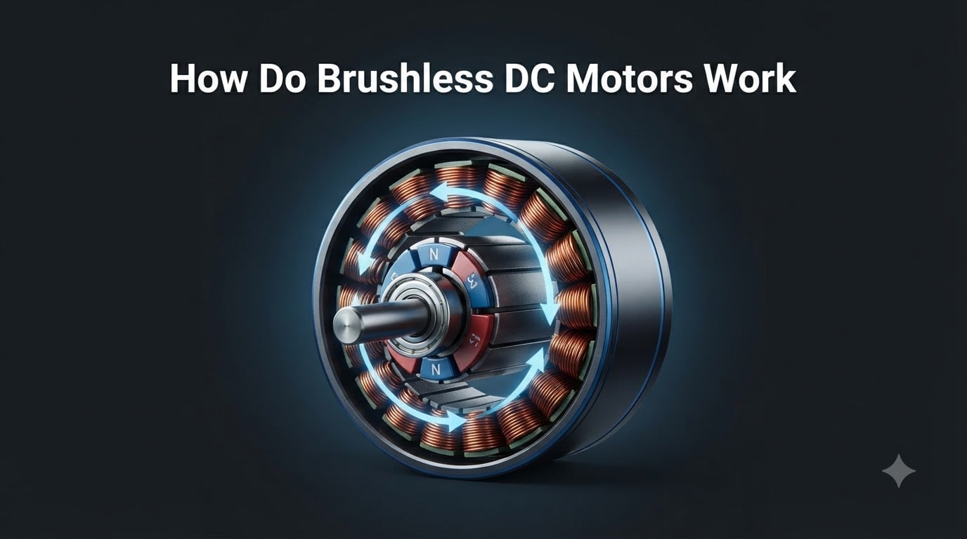
How do brushless DC motors work? At the simplest level, a brushless DC motor (BLDC) is an electric motor that spins a permanent-magnet rotor using a rotating magnetic field generated by stationary coils, with no physical brushes to wear out. An electronic controller switches DC power to the right coils at the right time, producing smooth, efficient, and highly controllable motion. I have torn down dozens of these motors in my workshop, and once you see the components together, the operating principle clicks in about five minutes.
This guide walks through the components, the working principle, the commutation process, and the real-world applications of BLDC motors. I will also compare them to brushed motors, break down inrunner versus outrunner designs, and answer the most common questions I see on robotics forums.
Table of Contents
What Is a Brushless DC Motor and Why It Matters
A brushless DC motor is a synchronous electric motor powered by direct current. The “brushless” name comes from the fact that it has no physical brushes or mechanical commutator to switch current inside the motor. Instead, an external electronic controller performs that switching function.
The rotating part, the rotor, holds permanent magnets. The stationary part, the stator, holds copper windings. When the controller energizes the windings in a precise sequence, they create a magnetic field that pulls and pushes the rotor’s magnets, producing continuous rotation.
Why does the name say “DC” if the coils are being switched on and off rapidly? Because the motor is still powered by a DC source like a battery. The controller internally converts that DC into a stepped, three-phase waveform. Functionally, it is a DC-powered motor with AC-like internal switching. This is the single most common point of confusion I see in beginner forums, and I will clear it up in the commutation section below.
BLDC motors matter because they deliver up to 90% efficiency, last 10,000+ hours in typical service, and require almost no maintenance. They power everything from computer fans to electric vehicle drive units.
Main Components of a Brushless DC Motor
Every BLDC motor, whether it is a tiny drone motor or a large industrial servo, contains four core components. Understanding each one makes the rest of the article much easier to follow.
The Stator and Stator Windings
The stator is the stationary outer part of the motor. In a BLDC motor, it is made of laminated steel sheets wrapped with copper wire coils. These coils are arranged in three groups, called phases, distributed around the inside of the stator.
Each phase is electrically offset by 120 degrees from the others. When current flows through a phase, it becomes an electromagnet with a north and south pole. By switching the current direction and which phase is active, the controller makes a magnetic field that effectively rotates around the stator.
The Permanent Magnet Rotor
The rotor is the spinning inner part of the motor. In a BLDC design, the rotor carries permanent magnets, typically neodymium-iron-boron (NdFeB) for high power density. The number of magnet poles varies; common configurations include 2, 4, 6, 8, or more poles.
More poles mean more torque per revolution at lower speeds. That is why industrial servo motors often have 8 or 12 poles, while tiny drone motors may use just 2. The trade-off is that more poles complicate the controller and reduce top-end speed.
The Electronic Speed Controller (ESC)
The ESC is the brain of a brushless DC motor. It takes DC power from the battery, switches it through the stator phases in the correct sequence, and regulates speed based on a control input (a throttle signal, PWM command, or fieldbus command).
An ESC contains power MOSFETs or IGBTs to switch high currents, a microcontroller running commutation logic, and often current and voltage sensing circuitry. The ESC is what makes a BLDC motor work compared to a brushed motor, which handles commutation mechanically.
Position Sensors and Feedback
To know which phase to energize, the controller needs to know the rotor’s position. There are two main approaches.
Hall effect sensors are small semiconductor devices embedded in the stator that detect magnetic field strength. They output a digital signal that tells the controller which of six positions the rotor is in. Three Hall sensors provide full 60-degree resolution.
Back-EMF sensing skips the sensors. The controller measures the voltage generated by the non-energized phase and uses it to infer rotor position. This is called sensorless control and is common in fan motors and cost-sensitive applications.
How Brushless DC Motors Work: The Working Principle
Now that the parts are clear, here is the actual sequence that happens every time a BLDC motor turns. I will use a simplified three-phase motor with two rotor poles because that is the easiest to visualize.
Step 1: Power Delivery to the Stator Coils
DC voltage from a battery enters the ESC. The ESC contains six power switches arranged in three half-bridge pairs, one for each phase. The controller turns on the right pair to send current through a specific stator coil.
Step 2: Magnetic Field Generation
Current flowing through a coil creates a magnetic field with a north and south pole. The direction of the field flips when the current direction reverses. The ESC deliberately switches current direction to flip the field polarity as needed.
Step 3: Electronic Commutation Sequence
The controller energizes the phases in a six-step sequence, each step lasting 60 electrical degrees. The pattern is: phase A positive, phase A negative with B positive, phase B negative, phase B negative with C positive, phase C negative, phase C negative with A positive, and so on. With each step, the active magnetic field jumps to the next pair of stator poles.
Why three wires? The three wires correspond to the three phase terminals of the stator. Each one is energized in turn to create the rotating field. The fourth wire you sometimes see in sensored motors is a separate connector for the Hall sensor signals and is not part of the power path.
Step 4: Continuous Rotation
Each time the stator field jumps, the permanent magnet rotor snaps to align with it because opposite poles attract. The momentum of the rotor carries it past the next alignment point just as the controller advances the field again. The result is smooth continuous rotation at a speed determined by how fast the controller advances through the commutation sequence.
The torque produced in a BLDC motor is roughly proportional to the phase current and the strength of the permanent magnets. If you want to know how torque is calculated, my guide on understanding torque in robotics breaks down the formulas in detail.
Electronic Commutation: The Key to Brushless Operation
Electronic commutation is the process that replaces the mechanical brush-and-commutator assembly found in brushed DC motors. Getting commutation right is what separates a working BLDC motor from a paperweight. Here is how the two main methods work.
Hall Effect Sensor Commutation
Three Hall sensors sit on the stator at 120-degree intervals. As the rotor magnets spin past each sensor, the sensor outputs a high or low signal depending on whether it sees a north or south pole. The combination of three signals creates six unique codes that map to the six commutation steps.
The controller reads the Hall code, waits for a short delay (commutation advance), then switches to the next phase combination. This gives precise, reliable commutation even at zero RPM, which is why sensored BLDC motors are preferred for robotics and CNC machines where you need to hold position.
Back-EMF Sensorless Commutation
When a BLDC motor spins, the rotor magnets induce a voltage in the unenergized phase. This is called back-EMF (back electromotive force). The controller measures this voltage, watches for the zero-crossing point, and uses that timing to trigger the next commutation step.
Sensorless control is cheaper because there are no extra parts, and it works well at higher speeds. The catch is that at very low speeds the back-EMF signal is too weak to measure reliably, so the motor has to be started in an open-loop mode. That is why cheap RC planes sometimes twitch or stutter on takeoff but run perfectly once airborne.
Square Wave vs Sine Wave Drive
The basic six-step commutation described above is square wave drive. Current is either fully on or fully off, and the torque ripple is moderate. Sine wave drive uses PWM to shape the phase currents into smooth sine waves, which dramatically reduces torque ripple and acoustic noise.
Sine wave drive is standard in high-end CNC servos, gimbals, and high-performance electric vehicles. It costs more in controller complexity, but the smoothness is worth it for precision applications.
Speed Control Methods for BLDC Motors
Speed control in a brushless DC motor is a separate function from commutation. Commutation decides which phase fires when; speed control decides how hard each phase fires. There are two common methods.
Pulse Width Modulation (PWM)
The ESC chops the DC supply at a high frequency (typically 8 to 50 kHz) and varies the duty cycle. A 50% duty cycle delivers half the average voltage to the motor; 100% delivers full voltage. By adjusting the duty cycle, the controller regulates speed.
PWM is efficient because the power switches are either fully on (low loss) or fully off (no loss). Almost all modern BLDC controllers use PWM for the speed-control loop.
Voltage and Current Control
For more precise speed regulation, the ESC implements a closed-loop control system. It measures the actual speed (from Hall sensors or back-EMF) and compares it to the target speed, then adjusts the PWM duty cycle up or down to correct any error.
Current control is also used to limit torque. The ESC monitors phase current and reduces PWM duty cycle if the current exceeds a safe limit, protecting the motor and driver from overload.
BLDC vs Brushed DC Motors: Key Differences
The most common comparison I get asked about is BLDC versus brushed. Here is the side-by-side breakdown based on my own testing and manufacturer data sheets.
Efficiency: BLDC motors typically achieve 85 to 90% efficiency, while brushed motors top out around 75 to 80%. The difference comes from brush friction and electrical losses in the mechanical commutator.
Lifespan: A brushed motor’s brushes wear out after 1,000 to 3,000 hours of operation, while a BLDC motor routinely runs 10,000+ hours. In drones and RC vehicles, the difference is the gap between a one-season motor and a decade of use.
Maintenance: Brushed motors need periodic brush replacement. BLDC motors are maintenance-free. They also run cooler because there is no brush friction, which is critical in continuous-duty applications.
Cost: BLDC motors cost more up front because of the ESC, but the total cost of ownership is usually lower once you factor in replacement brushes and downtime.
Noise: BLDC motors are quieter because there are no brush impacts. Sine-wave-driven BLDCs are nearly silent, which is why they dominate in high-end audio equipment and HVAC systems.
Power-to-weight ratio: BLDC motors win here too. Without a heavy commutator, more of the mass goes into magnets and copper, which is exactly what you want for drones and robotics.
Types of BLDC Motors: Inrunner vs Outrunner
BLDC motors come in two physical configurations, and choosing the right one matters for your application.
Inrunner motors have the rotor inside and the stator outside. The rotor spins at high RPM (often 20,000 to 50,000 RPM), and the outer stator is mounted to the motor housing for cooling. Inrunners are the classic choice for RC cars, electric scooters, and high-speed spindles.
Outrunner motors flip that arrangement: the rotor spins on the outside, the stator sits in the middle, and the rotating bell housing acts as a cooling fan. Outrunners produce more torque at lower RPM and are the standard for drone propulsion and direct-drive applications.
For robotics projects that need high torque at low speed without a gearbox, an outrunner is often the better pick. Pairing the motor with the right reduction stage is its own engineering topic, and you can read more about it in my piece on gear ratios in motor applications.
Common Applications of Brushless DC Motors
BLDC motors are everywhere once you start looking. Here are the most common categories I encounter in my work and on robotics forums.
Drones and multirotors: Every quadcopter and racing drone runs on outrunner BLDC motors. The combination of high power, low weight, and precise throttle control is unmatched by brushed alternatives.
Electric vehicles: Modern EVs use BLDC or PMSM (permanent magnet synchronous motor) variants for traction. Most major EV makers use them in some form, often with multiple motors per vehicle.
Industrial automation: CNC machines, robotic arms, conveyor belts, and pick-and-place systems rely on BLDC servomotors for precise positioning and repeatable motion.
Consumer electronics: Computer case fans, hard drives, optical drives, and even some camera gimbals use small BLDC motors for silent, long-life operation.
Medical devices: Ventilators, infusion pumps, surgical tools, and prosthetics benefit from the clean, quiet, and reliable operation that BLDC motors provide.
HVAC systems: Variable-speed compressors and blowers in modern air conditioners use BLDC motors to hit high efficiency ratings.
Frequently Asked Questions
What are the downsides of a brushless motor?
The main downsides of a brushless DC motor are higher upfront cost, the need for an external electronic speed controller, and more complex repair if the controller fails. They also require a control input to start, so they will not run when connected directly to a battery the way a brushed motor will.
Are brushless DC motors actually AC?
A brushless DC motor is powered by a DC source, but the controller internally switches the current to the stator coils in a pattern that creates an alternating magnetic field. So it is DC in, AC-like behavior inside, mechanical rotation out. Calling it a DC motor refers to its power input, not the waveform on the coils.
What is the lifespan of a brushless DC motor?
A well-built brushless DC motor typically lasts 10,000 to 20,000 hours of operation, and in some designs well over 50,000 hours. Because there are no brushes to wear out, the limiting factors are usually the bearings and the electronics rather than the motor itself.
Why do DC brushless motors have three wires?
Brushless DC motors have three wires because the stator is wound in three phases, each separated by 120 electrical degrees. Each wire carries current to one phase, and the controller energizes them in sequence to create a rotating magnetic field. The fourth or fifth wires found on some motors are for Hall sensor feedback, not power.
Conclusion: Why Brushless DC Motors Are the Modern Standard
How do brushless DC motors work? They use an electronic controller to switch DC current through three stator phases in a precise sequence, creating a rotating magnetic field that pulls a permanent-magnet rotor along with it. That single design choice delivers higher efficiency, longer life, and better control than any brushed alternative.
If you are picking a motor for a drone, robot, electric vehicle, or any high-duty-cycle application in 2026, brushless is almost always the right answer. Start with a sensorless outrunner for cost-sensitive hobby projects, or step up to a sensored sine-wave servo when you need precision and silence.