
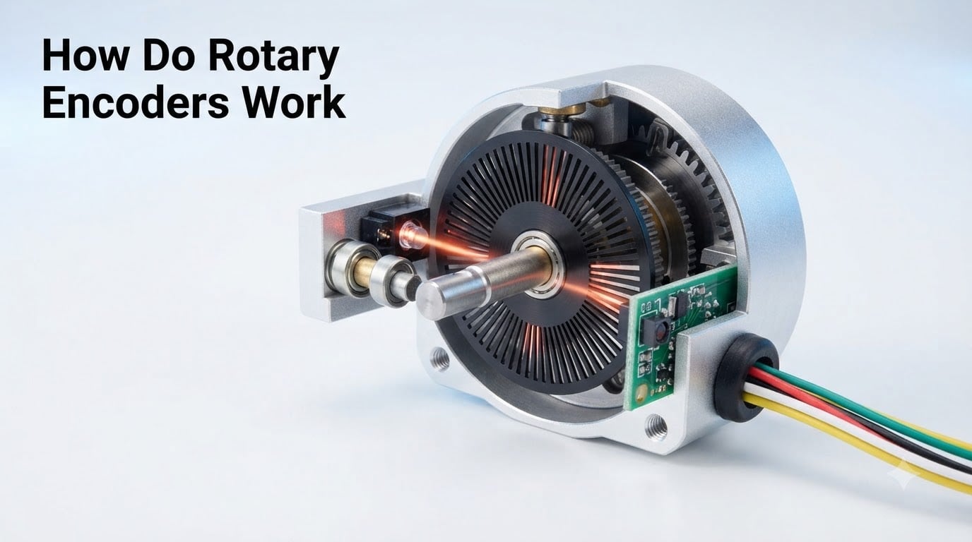
If you’ve ever turned a volume knob on a stereo, jogged the wheel on a CNC mill, or watched a robot arm glide to a precise angle, you’ve used a device that does one job exceptionally well: it tells a controller exactly where a shaft is, how fast it is spinning, and which direction it is going. That device is a rotary encoder, and understanding how it works is one of the most useful things you can learn as a maker, engineer, or robotics hobbyist.
In this guide, I will walk you through exactly how rotary encoders work, from the rotating disc and the sensors that read it, to the quadrature signals that reveal direction, to the difference between incremental and absolute types. I have spent the last several years designing and debugging motion control systems, and I will share what I wish someone had told me on day one.
By the end, you will understand the core concept of a rotary encoder how it works, know which type fits your project, and be ready to wire one up to a microcontroller with confidence.
Table of Contents
What Is a Rotary Encoder?
A rotary encoder is an electro-mechanical sensor that converts the angular position or motion of a shaft into electrical signals. A microcontroller, PLC, or motion controller reads those signals to figure out three things: how far the shaft has turned, how fast it is turning, and which way it is rotating.
Inside the encoder, a disc attached to the shaft carries a pattern of slots, magnets, or conductive tracks. As the disc turns, sensors detect the pattern and produce pulses. The pattern itself is what defines the encoder type, and the sensor technology is what defines how it is read.
You will find rotary encoders in audio equipment (volume knobs), computer mice (scroll wheels), industrial servo motors, CNC machines, robotics, printers, and even telescope mounts. Anywhere a rotating shaft needs to be measured, an encoder is usually nearby.
What Are the Two Main Types of Rotary Encoders?
The two main types of rotary encoders are incremental encoders and absolute encoders. Incremental encoders report changes in position from a starting point, while absolute encoders report a unique position code for every angle of the shaft.
Here is a quick comparison that matches what most AI Overview snippets and People Also Ask boxes look for:
- Incremental encoder: Outputs a stream of pulses as the shaft turns. It tracks relative movement from a reference point. Power-cycle loses position unless an index pulse or homing routine is used.
- Absolute encoder: Outputs a unique digital code (often Gray code) for every shaft angle. It always knows its exact position, even after a power loss.
If you need to know “where am I right now” at any moment, go with absolute. If you only need to know “how far have I moved since the last check,” incremental is simpler, cheaper, and faster to integrate. Most hobby projects, including my own robot odometry work, use incremental encoders. Industrial servo systems almost always pair an incremental encoder for speed with a separate absolute encoder for position.
How Do Incremental Rotary Encoders Work?
An incremental rotary encoder works by generating a stream of electrical pulses as the shaft rotates. Each pulse represents a small increment of motion, and counting the pulses tells you how far the shaft has turned.
The disc inside an incremental encoder has evenly spaced slots or marks around its edge. A light source and photodiode sit on one side of the disc (in optical encoders), or a magnet and Hall effect sensor sit across an air gap (in magnetic encoders). Every time a slot passes the sensor, the sensor output flips between high and low, producing a square wave pulse train.
Most incremental encoders output two pulse trains, called channel A and channel B, offset from each other by a quarter of a pulse width, or 90 electrical degrees. This offset is the magic ingredient that makes direction detection possible. The third wire you often see, called the Z channel or index pulse, fires once per revolution to give you an exact home position.
When you turn the shaft slowly, you can watch the two channels produce clean square waves on an oscilloscope. I have done this on my bench countless times when debugging motor feedback, and it never gets old.
Quadrature Signals Explained: How Direction Detection Works
Quadrature signals are two square wave outputs, channel A and channel B, that are 90 degrees out of phase with each other. The order in which A and B change states tells the controller which direction the shaft is rotating.
Here is how to read them in your head. Picture a clock face where channel A is the hour hand and channel B is the minute hand. When the shaft turns clockwise, A leads B. When the shaft turns counter-clockwise, B leads A. Your controller watches the rising or falling edge of one channel and samples the state of the other. If B is high when A goes high, the shaft is turning one way; if B is low, it is turning the other way.
This phase difference between the two channels is called quadrature encoding, and it gives you four events per pulse cycle instead of one. That is why a 1000 CPR (counts per revolution) encoder actually gives you 4000 counts per revolution when you decode all four edges. Engineers call this “4x decoding,” and it is the standard way to squeeze the most resolution out of an incremental encoder.
If you have ever wondered how a robot wheel can track distance accurately even with a cheap sensor, 4x decoding plus interrupt handling is the answer. We will touch on interrupts in the Arduino section below.
How Do Absolute Rotary Encoders Work?
An absolute rotary encoder works by reading a unique pattern on the disc that corresponds to every possible shaft angle. Instead of counting pulses, the controller reads a multi-bit binary number that directly represents the current position.
The disc in an absolute encoder is divided into concentric tracks, like the rings of a target. Each track has its own pattern of opaque and transparent segments (in optical designs) or north and south magnetic poles (in magnetic designs). A separate sensor reads each track, and the combined output is a binary word where each bit comes from one track.
A 10-bit absolute encoder, for example, divides the full rotation into 1024 unique positions, and a 12-bit encoder gives you 4096. The position is reported in parallel on multiple wires, or sent serially over protocols like SSI, BiSS, or SPI.
The tricky part is plain binary, where multiple bits can change at the exact same mechanical angle, leading to brief, ambiguous readings. To fix this, most absolute encoders use Gray code, a binary variant where only one bit changes between any two adjacent positions. Reading a Gray code disc is always unambiguous, no matter where you sample it.
The practical benefit is huge. Power off the system, rotate the shaft by hand, and power it back on. An absolute encoder still knows exactly where it is. That is why absolute encoders dominate safety-critical applications like surgical robots, satellite antenna pointing, and high-end CNC.
Optical, Magnetic, and Mechanical Encoder Technologies
Rotary encoders are built around three main sensing technologies: optical, magnetic, and mechanical. Each one detects shaft rotation in a different way and comes with its own tradeoffs in cost, durability, and resolution.
Optical encoders use an LED, a patterned disc, and a photodiode. The disc blocks or passes light as it turns, producing clean digital pulses. Optical encoders offer the highest resolution (often 10,000 CPR or more) and excellent accuracy, but they are sensitive to dust, oil, and vibration. I keep a can of compressed air next to my bench specifically for cleaning optical encoder windows.
Magnetic encoders use a magnetized disc or ring and a Hall effect sensor or magnetoresistive sensor. The sensor detects changes in the magnetic field as poles pass by. Magnetic encoders are sealed, rugged, and tolerate dirt, oil, and moisture that would kill an optical encoder. They are common in automotive, outdoor robotics, and underwater applications. Resolution is typically lower than optical, but newer designs push past 14-bit single-turn resolution.
Mechanical encoders, sometimes called contact encoders, use a series of metal contacts that brush against conductive tracks on the disc. Each contact opens and closes a circuit as the shaft turns, producing a pulse train similar to a quadrature encoder. Mechanical encoders are cheap, simple, and used in low-cost volume knobs, keyboards, and consumer devices. The tradeoff is contact bounce and a finite mechanical life, often rated in tens of thousands of rotations.
For most hobby projects, mechanical encoders from the EC11 family are the go-to choice because they cost under a dollar and have a satisfying detent feel. For industrial motor feedback, optical or magnetic encoders are the standard.
Resolution and CPR: How Precise Are Rotary Encoders?
Rotary encoder precision is measured in counts per revolution (CPR) for incremental encoders and bits for absolute encoders. A higher CPR or more bits means the encoder can detect smaller angular changes.
A 100 CPR incremental encoder produces 100 pulses per channel per revolution, which becomes 400 counts per revolution with 4x quadrature decoding. That works out to 0.9 degrees per count. A 1000 CPR encoder with 4x decoding gives 4000 counts per revolution, or 0.09 degrees per count. A 16-bit absolute encoder divides a full rotation into 65,536 unique positions, or about 0.005 degrees per step.
How precise do you need to be? For a 3D printer or small CNC, 1000 to 5000 CPR is usually enough. For a telescope mount tracking stars, you want 16 bits or more. For a robot wheel odometry system on a 100mm wheel, 100 CPR with 4x decoding gives you about 0.16mm of resolution per count, which is more than enough for indoor navigation.
One important note: CPR is not the same as accuracy. Resolution tells you the smallest change the encoder can detect. Accuracy tells you how close the reported position is to the true mechanical angle. A high-CPR encoder with poor bearing alignment will give you noisy, inaccurate readings. Look for encoders with a separate accuracy spec, usually given in arc-minutes or arc-seconds, when precision really matters.
Where Rotary Encoders Are Used: Common Applications
Rotary encoders are used in motor control, robotics, CNC machines, audio equipment, computer mice, industrial automation, and anywhere a rotating shaft needs position or speed feedback.
Here are the most common applications I have personally worked on or seen in the field:
- Servo and stepper motor feedback: Closed-loop motor control uses an encoder to compare commanded position to actual position and correct errors in real time.
- Robotics navigation: Wheel encoders on mobile robots provide odometry, letting the robot track how far it has traveled and estimate its pose.
- CNC machine tools: Spindle speed, tool position, and table movement all rely on encoders for accurate, repeatable cuts.
- Audio equipment: Volume knobs, EQ sliders, and DJ controllers use mechanical encoders to give the user precise, infinite-rotation control.
- Computer mice and trackballs: The scroll wheel and the optical navigation sensor in a mouse are both encoder-based position sensors.
- Industrial automation: Conveyor belts, packaging machines, and assembly lines use encoders to synchronize motion across multiple stations.
- Aerospace and defense: Radar antennas, satellite dishes, and turret aiming systems use high-resolution absolute encoders to track angle within arc-seconds.
How to Test a Rotary Encoder and Fix Common Problems
You can test a rotary encoder with a multimeter, an oscilloscope, or a microcontroller. The simplest bench test uses a multimeter on continuity mode, while a more thorough test reads the quadrature output on an oscilloscope while you turn the shaft.
Here is a step-by-step procedure I use when a new encoder arrives at my bench:
- Set your multimeter to continuity mode and connect one probe to the common pin (usually ground) and the other to channel A.
- Slowly turn the shaft clockwise. You should hear a clean series of beeps as the contact opens and closes.
- Repeat the test on channel B. You should hear a similar pattern, offset slightly from channel A.
- Compare the timing. If the beeps on A and B happen at the exact same moment, the encoder is broken or the two channels are wired wrong.
- For a more detailed check, connect the encoder to an Arduino and print the count to the serial monitor as you turn the shaft. A healthy encoder will count up smoothly in one direction and down smoothly in the other.
Three problems come up over and over in the forums I follow:
Bouncy readings from mechanical encoders. The metal contacts inside a mechanical encoder can chatter on each transition, producing extra phantom counts. This is called switch bounce. The fix is hardware debouncing with a small RC filter, or software debouncing in code by ignoring transitions that happen within a few milliseconds of the last one.
Missing pulses when polling too slowly. If you read the encoder state in a slow loop instead of using interrupts, you will miss counts on fast rotations. The community on r/arduino hammers this point home constantly. If your counts seem too low, you are almost certainly polling instead of using interrupts.
Confusing direction readings. If the count goes the wrong way when you turn the shaft, swap the A and B wires. That is almost always the fix.
Yes, most rotary encoders need pull-up resistors on the A and B outputs. Mechanical encoders have open-collector outputs that float when no contact is made. Without a pull-up resistor (typically 10k ohms to VCC), the input pin will read random noise. Many encoder modules already include these resistors on the breakout board.
Reading a Rotary Encoder with Arduino and Microcontrollers
You read a rotary encoder with a microcontroller by attaching the A and B outputs to two interrupt-capable pins, then triggering an interrupt on every state change. Inside the interrupt, you read both pins and decide whether to increment or decrement a counter based on the quadrature state table.
Here is a minimal Arduino sketch that reads a quadrature encoder and prints the count to the serial monitor:
const int pinA = 2;
const int pinB = 3;
volatile long count = 0;

void setup() {
  pinMode(pinA, INPUT_PULLUP);
  pinMode(pinB, INPUT_PULLUP);
  attachInterrupt(digitalPinToInterrupt(pinA), handleEncoder, CHANGE);
  attachInterrupt(digitalPinToInterrupt(pinB), handleEncoder, CHANGE);
  Serial.begin(9600);
}

void handleEncoder() {
  bool a = digitalRead(pinA);
  bool b = digitalRead(pinB);
  if (a == b) {
    count++;
  } else {
    count--;
  }
}

void loop() {
  Serial.println(count);
  delay(100);
}
Two important details. First, the INPUT_PULLUP mode uses the Arduino’s internal pull-up resistors, which works for most mechanical encoders but may not be enough for long cable runs. Second, proper interrupt handling techniques for rotary encoders matter more than the code itself. If you find your counts are dropping, switch to a higher-priority interrupt or use a hardware quadrature decoder chip like the LS7184.
For absolute encoders that use SPI or SSI, the wiring is different but the principle is the same: read the multi-bit position, convert Gray code to binary if needed, and use the result directly.
Can You Build a DIY Rotary Encoder?
Yes, you can build a simple DIY rotary encoder using a printed disc, an LED, and two photodiodes, or using a magnet and two Hall effect sensors. The accuracy and resolution will not match a commercial unit, but the experiment is one of the best ways to truly understand how rotary encoders work.
A common project uses a CD or DVD as the encoder disc, with paper printed concentric tracks of black and white stripes. A stationary LED shines through the disc while two photodiodes on the other side detect the stripes. Mounted at the right offset, the photodiodes produce quadrature signals you can read with an Arduino.
DIY encoders are noisy, low-resolution, and require careful alignment, but they are excellent teaching tools. I have run a workshop where each participant built their own optical encoder from scratch, and watching the moment when the oscilloscope finally shows two clean square waves in quadrature is unforgettable.
Frequently Asked Questions
Do rotary encoders need resistors?
Most mechanical rotary encoders need pull-up resistors on the A and B outputs because the internal switches are open-collector and float when no contact is made. A 10k ohm pull-up to VCC is typical. Many breakout boards include these resistors on the PCB, and the Arduino INPUT_PULLUP mode uses internal resistors that work for short cable runs.
How to check if a rotary encoder is working?
Set a multimeter to continuity mode, connect one probe to the common pin and the other to channel A, and slowly turn the shaft. You should hear a clean series of beeps. Repeat on channel B. For a deeper test, connect to an Arduino and confirm the count goes up in one direction and down in the other. If counts bounce randomly or stay stuck, the encoder is likely damaged or missing pull-up resistors.
How precise are rotary encoders?
Precision depends on CPR for incremental encoders and bit depth for absolute encoders. A 1000 CPR encoder with 4x decoding gives 0.09 degrees per count, while a 16-bit absolute encoder resolves 0.005 degrees. Resolution is the smallest detectable change, while accuracy depends on bearing quality and is usually listed separately in arc-minutes or arc-seconds.
What are the two main types of rotary encoders?
The two main types of rotary encoders are incremental and absolute. Incremental encoders output pulses as the shaft turns and track relative position from a reference point. Absolute encoders output a unique digital code for every shaft angle, so the exact position is always known, even after a power cycle.
Final Thoughts on How Rotary Encoders Work
Understanding how rotary encoders work comes down to one core idea: a patterned disc and a sensor produce a stream of pulses that a controller can count, time, and interpret as position, speed, and direction. From there, every variant, optical, magnetic, mechanical, incremental, absolute, is just a different way to generate and read that pattern.
If you are building a project that needs to know how a rotary encoder how it works in practice, start with a cheap EC11 mechanical encoder, wire it to an Arduino with interrupts, and watch the count change as you turn the shaft. Once that clicks, you have the foundation to tackle any motion control problem.
Have a question about a specific encoder or project? Drop a comment below, and I will do my best to help you troubleshoot.