
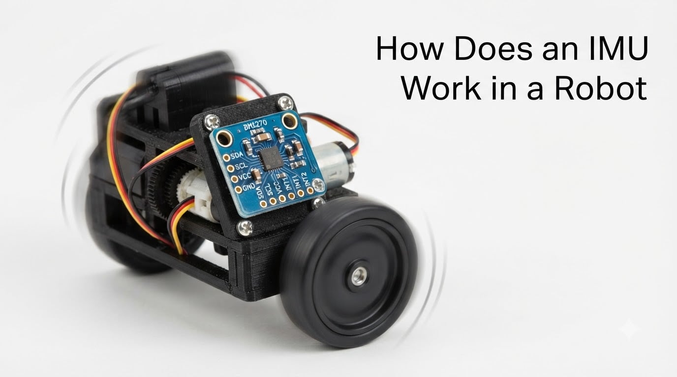
When I built my first self-balancing robot, the wheels spun out within two seconds. The problem was not the motors, the chassis, or the battery. The robot had no idea which way was up. Once I strapped an IMU to the frame and wrote a few lines of sensor fusion code, the same robot stood upright and rolled across the floor. That single change taught me why every serious mobile robot carries an IMU.
An IMU, or Inertial Measurement Unit, is the small sensor module that tells an IMU robot which way it is pointing, how fast it is rotating, and how it is accelerating. In this guide I will walk you through how does an IMU work in a robot, what is actually happening inside the chip, and how the data becomes useful orientation for a balancing, driving, or flying machine.
Table of Contents
What Is an IMU and Why Every Robot Needs One
An IMU (Inertial Measurement Unit) is an electronic device that measures a body’s specific force, angular rate, and orientation using a combination of accelerometers, gyroscopes, and sometimes magnetometers. In a robot, it acts as the inner ear and balance system combined, answering three questions hundreds of times per second: which way am I leaning, how fast am I turning, and am I speeding up or slowing down.
Without an IMU, a robot is essentially blind to its own motion. Wheel encoders tell you how far the wheels have spun, but not whether the robot is sliding sideways on a wet floor. A camera can see the world, but cannot feel a sudden gust of wind tilting a drone. An IMU fills that gap by giving the controller raw motion data at very high rates, usually 100 Hz to 1 kHz.
That data feeds the robot’s control loops. A self-balancing robot uses pitch angle to drive the wheels forward or backward. A quadcopter uses roll and pitch to mix motor speeds. An autonomous mobile robot uses heading changes to dead-reckon between known waypoints when GPS drops out. In every case, the IMU is the sensory backbone that makes the rest of the control system possible.
If you are just getting started with robot anatomy, our guide on how a robot chassis works is a good companion read. The chassis is what the IMU is mounted to, so the two topics connect directly.
The Core Components Inside an IMU
Most IMUs are built from three sensor types, and understanding each one is the key to understanding how does an IMU work in a robot. Each sensor measures something different, and only by combining them do you get a complete picture of motion.
Accelerometer: How the Robot Feels Gravity and Motion
An accelerometer measures specific force, which is the combination of true acceleration and the gravitational pull acting on the sensor. When your robot is sitting still, the accelerometer reads 1g straight up because gravity is pulling the proof mass down at 9.81 m/s². When the robot accelerates forward, the reading tilts slightly in the opposite direction because of inertia.
By placing three accelerometers on perpendicular axes (X, Y, Z), the IMU gets a 3D vector of acceleration. This vector tells the controller two useful things: which way is down (great for tilt estimation) and how the robot is changing speed. The catch is that an accelerometer alone cannot distinguish between gravity and motion. A robot at rest on a 30° slope looks identical to a robot accelerating horizontally at 0.5g. That is why a single accelerometer is not enough.
Gyroscope: How the Robot Tracks Rotation
A gyroscope measures angular velocity, or how fast the robot is rotating around each axis, in degrees per second or radians per second. A three-axis gyroscope gives you rotation rate around X, Y, and Z simultaneously. Integrate that rate over time and you get the total angle the robot has turned through. This is the only direct measurement of rotation in an IMU, and it is essential for fast, responsive control.
The downside is drift. A tiny bias error in the gyroscope, even 0.01 degrees per second, adds up to 0.86 degrees of error per minute, or about 50 degrees per hour. Over long runs, the integrated angle drifts away from reality. That is why IMUs almost always fuse the gyroscope with another sensor.
Magnetometer: The Digital Compass
A magnetometer measures the strength of the Earth’s magnetic field along three axes, which gives an absolute heading reference. It is the digital equivalent of a compass needle, and it solves the gyroscope’s drift problem in the yaw axis. When your robot turns 360°, the gyroscope says it turned 361° because of bias, but the magnetometer still says the heading is the same as where you started.
The trade-off is noise and interference. Motors, batteries, and even the steel frame of a robot can distort the magnetic field. Magnetometer data is also slower to update and less precise than gyroscope data, which is why the two are always fused rather than used directly.
How MEMS Technology Makes Modern IMUs Possible
Almost every IMU you will find on a robot today is a MEMS device, which stands for Micro-Electro-Mechanical Systems. A MEMS accelerometer is a tiny silicon structure with a suspended proof mass that moves when the chip accelerates. That motion changes the capacitance between interlocking fingers, and the chip’s circuitry turns that change into a digital number.
A MEMS gyroscope works on the Coriolis effect. The chip vibrates a small mass at a fixed frequency, and when the chip rotates, the mass deflects sideways by a tiny but measurable amount. That deflection is read out as angular rate. The entire structure fits inside a package smaller than a pencil eraser, costs a few dollars, and consumes milliwatts of power.
This is a huge shift from the early IMUs. The Apollo spacecraft used a 32 kg IMU built from precision gyroscopes. A modern smartphone IMU weighs less than a gram and costs under $5. That price collapse is what made consumer drones, robot vacuums, and hobby self-balancing robots possible. For a robot builder in 2026, MEMS is the default technology and the only one that makes sense at hobby scale.
How an IMU Measures Motion: Pitch, Roll, and Yaw
To describe a robot’s orientation in 3D space, you need three angles: pitch, roll, and yaw. These come straight from how does an IMU work in a robot, and understanding them is critical for any project that involves balance or directional motion.
Pitch is the rotation around the left-right axis, which makes the robot nod its nose up and down. Roll is rotation around the front-back axis, which tilts the robot left and right. Yaw is rotation around the vertical axis, which is the compass direction the robot is facing. A 6-axis IMU measures pitch and roll directly, plus yaw rate, while a 9-axis IMU also gives absolute yaw via the magnetometer.
In practice, the raw sensor data does not equal the angles directly. The accelerometer gives you a tilt vector in g’s. The gyroscope gives you rotation rate in degrees per second. To get the actual angle, you need to fuse those two streams, which is where sensor fusion comes in.
Imagine your robot tips forward 10°. The gyroscope reports a brief spike of positive pitch rate, then settles to zero. The accelerometer reads a vector tilted 10° off vertical. By combining both, the IMU can output a stable, drift-free angle. Our piece on how Wi-Fi control works on a robot is another good primer on how sensors feed a control system, in that case for remote operation.
From Raw Data to Robot Orientation: Sensor Fusion Explained
Raw accelerometer and gyroscope data is noisy and biased on its own. Sensor fusion is the software layer that turns that messy data into a clean, usable orientation estimate. This is the most important part of how does an IMU work in a robot, because the sensor is only as good as the algorithm that interprets it.
The most common approach is the Kalman filter, a recursive algorithm that predicts the robot’s next state, compares it to the next sensor reading, and updates an internal estimate. The filter maintains a covariance matrix that tracks how uncertain it is about each state, and it weights new measurements more or less heavily based on that uncertainty. When the gyroscope is trustworthy and the accelerometer is noisy, the filter leans on the gyro. When the gyroscope has drifted, the filter leans on the accelerometer.
A simpler alternative is the complementary filter, which is a weighted average of two estimates. A typical implementation is angle = 0.98 * (angle + gyro_rate * dt) + 0.02 * accel_angle. The 0.98 keeps the responsive gyroscope data, while the 0.02 slowly corrects drift using the accelerometer. For most hobby robots, this works almost as well as a full Kalman filter and runs in a few lines of code.
Some IMU modules, like the popular BNO055, do this fusion on-chip. The microcontroller just reads out a quaternion or Euler angle over I2C, and the heavy lifting is done by the sensor itself. That is why modules like the BNO055 are popular with beginners. If you are using an MPU6050 or BMI270, you write the fusion code yourself, usually by porting an open-source filter like Mahony or Madgwick.
Our guide on how planetary gearboxes work in robot joints covers a totally different sensor system, but the principle is the same: raw data plus a model gives you the truth you actually need.
Common IMU Configurations: 6-DoF, 9-DoF, and IMU Grades
When you shop for an IMU, you will see numbers like 6-axis, 9-axis, 6-DoF, and 9-DoF. DoF stands for degrees of freedom, which is the number of independent measurements the sensor gives you. A 6-DoF IMU has a 3-axis accelerometer and a 3-axis gyroscope, which is enough for full 3D orientation except absolute heading. A 9-DoF IMU adds a 3-axis magnetometer, giving you absolute heading as well.
For most indoor robots, 6-DoF is plenty. Drones almost always use 6-DoF, because the magnetic field near the motors and power wiring is too noisy for a magnetometer to be useful outdoors or near a flight controller. Outdoor ground robots, especially those that need to maintain a heading over long distances, benefit from 9-DoF.
There is also a quality tier. Consumer MEMS IMUs like the MPU6050 cost a few dollars and drift a few degrees per minute. Industrial IMUs from Xsens or VectorNav cost hundreds of dollars and drift a few degrees per hour. Tactical and navigation-grade IMUs use fiber-optic or ring-laser gyroscopes and cost thousands. The rule of thumb is that price scales roughly with bias stability, and you pay for every order of magnitude of improvement.
Where Robots Use IMUs: Real-World Applications
Almost every mobile robot you can think of uses an IMU somewhere in its stack. Drones are the most obvious example. A quadcopter is inherently unstable, and it falls out of the sky in milliseconds without continuous IMU-driven feedback. Flight controllers read gyroscope data at 1 kHz or more to mix motor commands and keep the aircraft level.
Ground robots use IMUs for balance and dead reckoning. Self-balancing robots like the Segway and many two-wheeled hobby platforms rely entirely on IMU pitch to stay upright. Wheeled service robots use the IMU to track heading between wheel slip events, and to recover when the wheels briefly lose traction.
Robotic arms and humanoids use IMUs for body pose estimation. A walking humanoid robot places an IMU on the torso, often with additional units on the limbs, to know where each part of the body is in space. Industrial AGVs use IMUs plus wheel odometry to follow a path even when the floor markings are dirty. Even surgical robots and camera gimbals rely on IMUs for fine motion control.
Our article on how robotic grippers work is a good read if you want to see how end-effector sensors complement the body-level IMU on a typical robot.
Common IMU Problems and How to Fix Them
Anyone who has worked with IMUs for a while has hit the same handful of problems. The good news is that each one has a known fix, and you do not need to be a control engineer to apply them.
The first issue is noise. Raw accelerometer and gyroscope data jitters even when the robot is sitting still. The fix is a low-pass filter, a moving average, or a properly tuned Kalman filter. Many off-the-shelf IMU libraries include this in their default configuration.
The second issue is drift. Even after filtering, the integrated angle slowly wanders. The fix is to fuse with the accelerometer (and magnetometer, if you have one) and to recalibrate the gyro bias at startup while the robot is stationary.
The third issue is vibration. Motors and gearboxes shake the IMU, and that vibration shows up as fake acceleration. The fix is mechanical: mount the IMU on a soft foam pad or vibration isolator, away from the motors. The fourth issue is magnetic interference, which can ruin magnetometer readings. The fix is to mount the magnetometer on a plastic stalk away from the battery and motor wiring.
Finally, there is the question of which IMU to buy. From the robotics community, TDK InvenSense modules are widely recommended for hobby work because they are cheap, well-documented, and supported by almost every flight controller firmware. The BNO085 is praised for doing the sensor fusion on-chip, which saves you a lot of code, but it costs more. For most hobby projects in 2026, a 6-axis MPU6050 or BMI270 is more than enough.
Frequently Asked Questions
What is an IMU and how is it used in robotics?
An IMU, or Inertial Measurement Unit, is an electronic device that measures a body’s specific force, angular rate, and orientation using a combination of accelerometers, gyroscopes, and sometimes magnetometers. In robotics, an IMU tells a robot which way it is pointing, how fast it is rotating, and how it is accelerating. That data feeds the control loops that keep a drone level, a balancing robot upright, or an autonomous vehicle on course.
Is an IMU the same as a gyroscope?
No, an IMU is not the same as a gyroscope. A gyroscope only measures angular velocity, or how fast something is rotating. An IMU is a multi-sensor module that typically includes a 3-axis gyroscope, a 3-axis accelerometer, and often a 3-axis magnetometer. The IMU combines all of those into a single unit that outputs orientation, motion, and sometimes heading.
Is an IMU just an accelerometer?
No, an IMU is more than an accelerometer. An accelerometer only measures linear acceleration and the direction of gravity. An IMU combines an accelerometer with a gyroscope, and usually a magnetometer, so it can measure rotation, acceleration, and absolute heading at the same time. The accelerometer alone cannot tell you how fast something is rotating, but the IMU can.
How much does an IMU cost?
IMU prices range from a few dollars to thousands, depending on the grade. Hobby-grade MEMS IMUs like the MPU6050 or BMI270 cost between $2 and $15. Smart sensor modules with on-chip fusion like the BNO055 cost between $30 and $50. Industrial IMUs from companies like Xsens and VectorNav cost several hundred dollars. Navigation-grade IMUs for aerospace and defense can cost tens of thousands of dollars.
Why are IMUs so expensive at the high end?
High-end IMUs are expensive because the precision components inside them are difficult to manufacture. Navigation-grade IMUs often use fiber-optic gyroscopes or ring-laser gyroscopes, which require extremely tight mechanical tolerances and individual calibration. Even MEMS IMUs at the industrial level are tested and compensated for temperature, vibration, and bias drift, all of which add to the cost. The price reflects how stable the bias is over time, and every order-of-magnitude improvement in stability roughly multiplies the price.
How an IMU Fits Into Your Next Robot Project
So, how does an IMU work in a robot? It works as a fast, multi-sensor motion reporter that turns physics into numbers your microcontroller can read. An accelerometer feels gravity and linear motion. A gyroscope tracks rotation. A magnetometer, when present, locks in absolute heading. Sensor fusion software, either on-chip or in your code, fuses those streams into a clean orientation estimate that the rest of the control system can trust.
If you are starting a new build in 2026, pick a 6-DoF MEMS module like the MPU6050 or BMI270 for indoor balance and tilt work, or a 9-DoF module if you need absolute heading. Mount it away from motors and vibration. Calibrate the gyro bias at startup. Run a simple complementary filter to start, then graduate to a Mahony or Madgwick filter once you are comfortable. From there, your IMU robot will have the sense of balance and motion that turns a pile of parts into a real machine.