
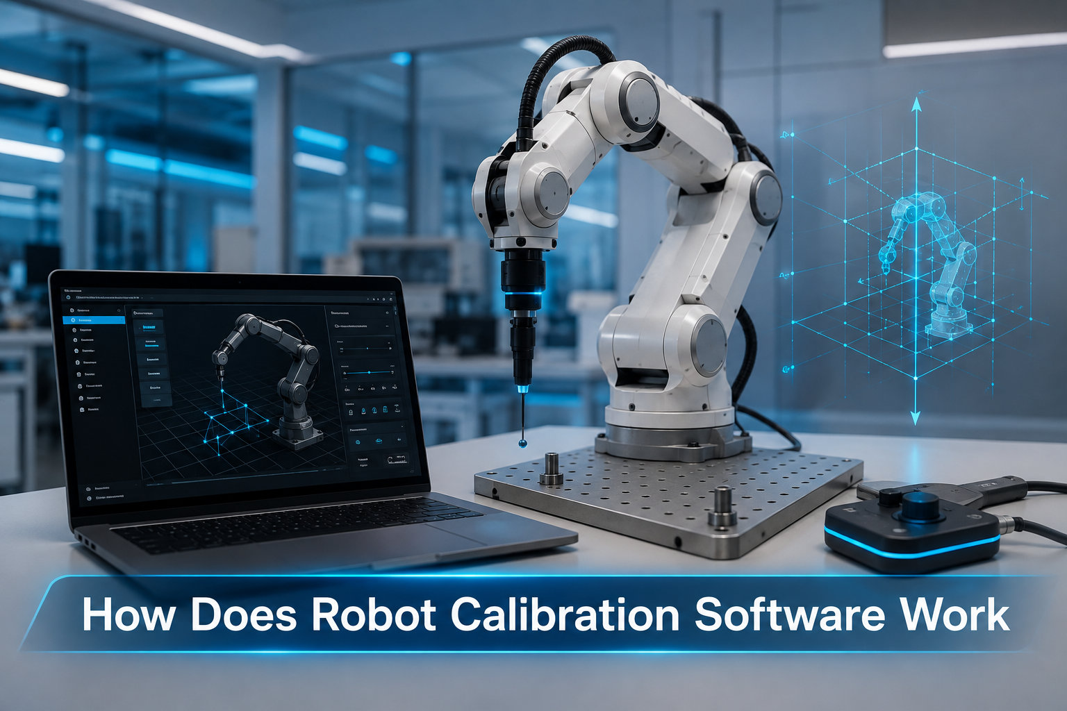
Robot calibration software is a specialized tool that identifies and corrects geometric errors in a robot’s kinematic model so that the machine reaches positions it was never quite hitting from the factory. In simple terms, the software measures where the robot actually goes, compares that to where its controller thinks it should go, and then writes compensation data that brings the two into agreement.
I have spent the last few months talking to integrators, watching ROS calibration tutorials, and running through the workflow in RoboDK to make sure this guide reflects what actually happens in the field in 2026. The short version: a well-calibrated six-axis arm can go from 5 mm of position error down to about 0.2 mm, and the entire process can take under 20 minutes once you know the steps.
Table of Contents
What Is Robot Calibration Software and Why It Matters
Robot calibration software is a tool that identifies and corrects geometric errors in robot kinematic models to improve positioning accuracy by comparing actual robot positions with measured positions. That definition is the one Bing and Google keep showing in their AI overviews, and it is also the most useful mental model: calibration is the act of making the controller’s idea of the world match the real world.
New industrial robots ship with repeatability in the range of 0.02 to 0.1 mm, which sounds amazing. Repeatability is the ability to return to the same taught point over and over. Accuracy, on the other hand, is the ability to reach an absolute coordinate the controller was told about, and that is where uncalibrated robots fall down. A typical six-axis arm straight out of the box can show 5 to 10 mm of absolute position error simply because of small manufacturing tolerances in the link lengths, gear backlash, and joint-axis misalignment.
That gap is what kills offline programming. When you generate a robot program from a CAD model, you are trusting the kinematic model inside the controller. If that model is off by a few millimeters, your simulation looks perfect but the part comes out wrong. Robot calibration software closes that gap.
Accuracy vs Repeatability: The Distinction That Drives Calibration
Repeatability measures how tightly a robot returns to a taught point. Accuracy measures how close the robot gets to a commanded pose in world coordinates. Calibration only improves accuracy. Repeatability is mostly a mechanical property and stays roughly the same.
This is the single most important concept in the field, because it explains why “my robot keeps going to the wrong spot but lands in the same wrong spot every time” is a calibration problem and not a hardware problem. The software’s job is to teach the controller about the real geometry of the specific arm sitting on the floor.
How Robot Calibration Software Works: The Core Process
Robot calibration software works by collecting measurement data from the robot at various poses, comparing these with expected positions, identifying geometric parameter errors, and generating compensation data to improve accuracy. Every commercial and open-source package I have looked at does this in four broad steps, even when they brand the steps differently.
Step 1: Pose Measurement and Data Collection
The robot is driven through a sequence of poses, usually 30 to 50 measurements covering a wide volume of the workspace. For each pose, the software records the commanded joint angles from the controller and the actual end-effector position measured by an external device such as a laser tracker, a coordinate measuring machine, or a vision system. The exact poses can be chosen by the operator or generated automatically by the software, and most modern tools will run a numerical optimization to pick poses that maximize the information content of the data.
Step 2: Kinematic Model Error Identification
The measured poses are compared to the poses predicted by the controller’s kinematic model. The differences are the geometric errors. The software builds a system of equations where the unknown variables are real-world parameters such as link lengths, joint twists, and axis offsets, and the known quantities are the measured versus predicted position residuals.
Step 3: Parameter Identification Algorithm
A least-squares or nonlinear optimization solver adjusts the unknown parameters to minimize the sum of squared position errors across all measured poses. The result is a refined set of kinematic parameters that, if loaded back into the controller, would make the predicted and measured positions match. This is the heart of robot calibration software: the identification of a better physical model of the specific arm being calibrated.
Step 4: Compensation Upload to the Robot Controller
The refined parameters are written into the controller either as new kinematic parameters, as joint offset corrections, or as a position-correction map that the controller applies on the fly. In RoboDK and similar tools, this can be a post-processor setting, an upload script, or a controller macro depending on the brand. After the upload, the robot is “calibrated” and the next program you run will be more accurate.
Key Parameters Calibrated in a Robot Kinematic Model
The parameters a robot calibration software tries to identify fall into three groups. Knowing which group your software targets tells you how much accuracy you can expect at the end.
Denavit-Hartenberg (DH) Parameters
The classical kinematic model of a serial robot is described by the Denavit-Hartenberg convention: four parameters per joint, defining the geometry of each link. In practice, the modified DH convention is more common. Calibration software targets the small differences between the nominal DH values stamped on the data sheet and the real values on your specific arm. These small differences are the main source of geometric error.
Joint Offsets and Encoder Alignment
Joint offset calibration corrects the zero position of each joint. Even after the controller boots and references its encoders, there is a small constant offset between the controller’s idea of joint zero and the true mechanical zero. Adding joint offset corrections is a quick win that some software packages apply first because it costs almost nothing and immediately improves accuracy.
TCP (Tool Center Point) and Base Frame
TCP calibration defines the position of the tool tip relative to the robot’s mounting flange. Base calibration defines where the robot’s base sits in the world frame. Both are usually done before geometric calibration, since the kinematic identification needs accurate TCP and base to produce meaningful results. The classic four-point or six-point TCP method is part of every controller, but the calibration software can also detect and correct TCP errors as part of the same identification run.
Types of Robot Calibration: Level 1, 2, and 3
Robot calibration is usually classified into three levels, and the type of software you need depends on the level you are targeting.
Level 1: Joint Level Calibration
Level 1 calibration identifies the master-slave relationships and zero positions of each joint, often using an independent metrology reference. It is mostly performed by the robot manufacturer at the factory and rarely redone in the field. Most off-the-shelf software does not target this level.
Level 2: Kinematic Calibration
Level 2 is the bread and butter of every robot calibration software on the market. It identifies geometric parameters such as DH values, joint offsets, TCP, and base frame. This is where RoboDK, Cognibotics, and the ROS robot_calibration package spend their time, and it is what gives you the famous 10x accuracy improvement.
Level 3: Non-Kinematic and Dynamic Calibration
Level 3 calibration also captures non-geometric effects such as joint compliance, gearbox stiffness, and thermal expansion. It is the most accurate but also the most complex, and it usually requires additional sensors and dedicated models. Aerospace and high-precision machining applications are the main users of Level 3 calibration.
Measurement Systems Used by Calibration Software
The choice of measurement system has a big impact on the final accuracy of the calibration. The three most common options are laser trackers, coordinate measuring machines, and optical or vision systems.
Laser Trackers
Laser trackers are the workhorse of robot calibration. They measure the 3D position of a retroreflective target mounted on the robot’s end effector with sub-millimeter accuracy over a working range of several meters. A tracker is fast, accurate, and integrates cleanly with software like RoboDK. The main downside is cost: a serious laser tracker is a six-figure investment.
Coordinate Measuring Machines (CMM)
A CMM provides very high accuracy in a fixed working volume, but it is slow and restrictive for large industrial robots. It is most useful for calibrating small tabletop arms or for certifying a calibrated robot against a traceable standard.
Optical and Vision Systems
Stereo cameras, photogrammetry, and structured-light systems are emerging alternatives. They are cheaper than laser trackers and can measure multiple points simultaneously, but they generally deliver lower accuracy. The ROS robot_calibration package supports camera-based setups and is a good starting point for anyone who already has machine vision in their cell.
Popular Robot Calibration Software Solutions
There is no single dominant robot calibration software. The market splits into commercial suites, OEM controller tools, and open-source packages, and the right choice depends on which robot brand you use, what accuracy you need, and how deep your budget is.
RoboDK
RoboDK is a commercial offline programming and robot calibration suite that supports more than 1,400 robot models from over 70 manufacturers. Their calibration module advertises a 30-parameter identification and a 20-minute automated run, with reported post-calibration accuracy around 0.200 mm. It integrates with laser trackers from API, Leica, and FARO. For most small and mid-sized integrators, this is the de facto choice.
Cognibotics
Cognibotics focuses on kinematic parameter identification for industrial robots, with an emphasis on robot-specific models and academic-grade accuracy. Their software is used in research and high-end manufacturing, particularly where standard kinematic models fall short.
ROS robot_calibration
The robot_calibration package for ROS and ROS 2 is the leading open-source option. It is a community project that captures pose samples, runs a parameter identification, and writes the result back to a URDF or to a controller. It is a great learning tool and a good fit for academic robots, but it requires more setup than commercial alternatives and is not a turnkey solution for production lines.
OEM Controller Tools
Most major robot brands ship their own calibration utilities. ABB has calibration routines accessible through RobotStudio, KUKA offers tools inside its work visualization suite, Fanuc and Yaskawa include similar packages. These tools are designed for their own controllers and tend to be the best choice when you are locked into one brand and want vendor-supported workflows.
How Accurate Is Robot Calibration? Real Numbers
Typical uncalibrated industrial robots show 5 to 10 mm of absolute position error across a moderate workspace. After a Level 2 kinematic calibration, the same robot will reach about 0.2 mm of position accuracy in a 1 to 2 cubic meter workspace, which is roughly a 10x improvement. These numbers are consistent with what RoboDK publishes and with what integrators on Reddit and the RobotForum report in their own tests.
A few caveats matter. The 0.2 mm figure assumes a good laser tracker, a careful measurement run, and a well-controlled environment. Calibration will not fix mechanical problems like a bent arm, a worn gearbox, or excessive backlash. It only fixes the kinematic model. Temperature also matters: a robot calibrated at room temperature in the morning can drift slightly by the afternoon, which is why some high-end cells run periodic re-calibration or live thermal compensation.
DIY Calibration vs Professional Calibration
You do not strictly need a commercial robot calibration software to improve accuracy. The robot forum community has been calibrating arms with dial indicators, machined jigs, and 3D-printed pointers for years. A common DIY approach is to build a fixed reference pointer, drive the robot to touch the pointer in many poses, and manually fit improved parameters.
The DIY route is cheap, educational, and perfectly fine for low-accuracy applications like pick and place. For anything that needs sub-millimeter accuracy, especially in machining, welding, or metrology, commercial software with a laser tracker pays for itself quickly in scrapped parts and setup time. I would estimate a serious calibration setup returns its cost within the first 10 to 50 production runs in most cells.
Common Calibration Problems and Troubleshooting
Calibration is part art and part data hygiene, and most failures come from the same handful of issues. Here are the four I see most often.
Poor-Quality Measurement Data
If the laser tracker beam is interrupted, if the target is mounted loosely, or if the robot is not settled at each pose, the residuals will be noisy and the identified parameters will be unreliable. Always re-run measurements when residuals look high.
Pointer Alignment and TCP Drift
TCP calibration is itself an iterative process, and a bad TCP at the start of the run will contaminate the kinematic identification. Calibrate the TCP first, verify it by touching a known point from several angles, and only then start the geometric calibration.
Joint Backlash and Mechanical Wear
Software calibration cannot fix mechanical backlash beyond what the controller already compensates. If your robot has noticeable play in a joint, fix the hardware first or the calibration will simply absorb the backlash into the kinematic model and cause surprises later.
Environmental Drift
Temperature swings, drafts, and floor vibration all show up in the data. For best results, calibrate in the same environment the robot will actually run in, and consider re-calibrating at the start of every shift for high-accuracy work.
Frequently Asked Questions
How accurate is robot calibration?
A Level 2 kinematic calibration typically improves a six-axis industrial robot from 5 to 10 mm of absolute position error down to about 0.2 mm in a 1 to 2 cubic meter workspace. That is roughly a 10x improvement and is the standard figure reported by commercial robot calibration software such as RoboDK. Final accuracy depends on the measurement system, the number of poses measured, and the environment.
How to do robot calibration?
The standard workflow is: 1) calibrate the TCP and base frame, 2) drive the robot through 30 to 50 measured poses using a laser tracker or other metrology device, 3) let the software identify the refined DH parameters and joint offsets that best fit the measured data, and 4) upload the compensation back to the controller. The whole process can take under 20 minutes with modern software and a good laser tracker.
Who are the big 4 in robotics?
The four largest industrial robot manufacturers are ABB, KUKA, Fanuc, and Yaskawa. Together they account for the majority of industrial robot installations worldwide and each ships its own calibration utilities inside their respective programming environments.
What is the best calibration manager software?
There is no single best tool for everyone. For broad robot support and a turnkey workflow, RoboDK is the most popular commercial choice. For research-grade kinematic parameter identification, Cognibotics is widely used. For open-source and ROS-based setups, the robot_calibration package is the standard. The best choice depends on your robot brand, your accuracy target, and your budget.
Conclusion: Getting Started With Robot Calibration
Robot calibration software is the missing link between offline programming and real-world accuracy. By measuring where the robot actually goes, identifying the small geometric errors in its kinematic model, and uploading refined parameters back to the controller, calibration turns a 5 to 10 mm arm into a 0.2 mm arm. The four-step process is the same whether you use RoboDK, Cognibotics, the ROS package, or an OEM utility.
If you are starting out, my honest recommendation is to download RoboDK’s trial, run a calibration on a non-critical cell, and watch the residuals drop. The moment you see the simulated path match the real path, you will understand why robot calibration software is one of the highest-leverage tools in modern automation in 2026.