
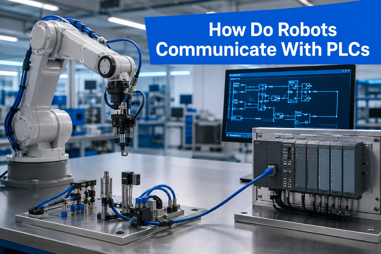
If you have ever walked through a modern factory and watched a robotic arm pick, place, and weld in perfect rhythm, you have seen the result of a quiet conversation. That conversation happens between the robot controller and a programmable logic controller, and it is one of the most important conversations in industrial automation. I have spent years working on robotic cells, and I still find it satisfying to see two controllers hand off signals to each other every few milliseconds.
In this guide, I will walk you through exactly how robots and PLCs talk to each other. We will look at the protocols, the signals, the configuration steps, and the brand-specific quirks that catch people out. By the end, you should be able to picture the data flow, choose the right protocol, and troubleshoot the most common errors without panic.
Table of Contents
How Do Robots Communicate With PLCs: The Basics
Robots communicate with PLCs through standardized industrial fieldbus protocols that carry digital signals, status flags, and program commands between the two controllers. In simple terms, the PLC sends a command bit, the robot controller acknowledges it, and both devices exchange a steady stream of status and feedback bits so the cell stays coordinated. The phrase how do robots communicate with PLCs really comes down to four things: a shared protocol, physical wiring or Ethernet, mapped memory addresses, and a handshaking routine that keeps both sides in sync.
Why not just let the robot do everything? A robot controller is excellent at motion, but it is a poor coordinator of an entire cell. The PLC is built to coordinate. It monitors conveyors, vision systems, safety circuits, and operator panels at once. When the PLC drives the robot, you get a system that is both precise in motion and reliable in orchestration.
According to forum discussions, the most common pain point for beginners is not the protocol itself but the expectation that the robot will run autonomously without a coordinator. As one integrator on a robotics forum put it, “the robot is a fancy servo, the PLC is the brain.” That mental model is the right starting point.
The Role of PLCs in Industrial Robot Cells
A PLC sits between the robot controller and the rest of the factory. It acts as the conductor of the orchestra. The robot plays its part, the conveyor moves parts in, the vision system inspects them, and the PLC decides when each player should act.
Here is what the PLC typically handles in a robotic cell:
- Sequencing robot programs based on part presence and process conditions
- Coordinating conveyors, grippers, and rotary tables
- Monitoring safety circuits, light curtains, and emergency stops
- Communicating with the factory MES or SCADA system
- Handling fault recovery and operator interfaces
The robot controller, by contrast, focuses on motion planning, path execution, servo loops, and program storage. It is extremely good at these tasks but has limited visibility into the rest of the cell. By linking the two, you get motion expertise from the robot and orchestration expertise from the PLC.
This separation of duties is also why ladder logic remains dominant in robotic cell design. Ladder logic is excellent for boolean decision-making, which is exactly the kind of work the PLC does in this partnership. If you want to brush up on related hardware communication patterns, our piece on how development boards communicate with sensors covers similar concepts at a smaller scale.
Communication Protocols Used Between Robots and PLCs
The protocol is the language the two controllers speak. Choosing the right one shapes everything from wiring cost to cycle time. There are four protocols you will encounter most often: Ethernet/IP, PROFINET, EtherCAT, and traditional digital I/O. Each has its place.
Below is a quick comparison based on what integrators most commonly deploy in robotic cells.
| Protocol | Medium | Cycle Time | Best Use Case |
|---|---|---|---|
| Ethernet/IP | Standard Ethernet | 1-10 ms | Rockwell/Allen-Bradley cells, Fanuc integration |
| PROFINET | Standard Ethernet | 0.5-1 ms | Siemens cells, KUKA and many European OEMs |
| EtherCAT | Standard Ethernet | Under 0.5 ms | High-speed motion, Beckhoff-based cells |
| Digital I/O (24V) | Dedicated wiring | Hardware scan | Small cells, simple handshakes, low-budget setups |
| DeviceNet / Profibus | Legacy fieldbus | 2-5 ms | Older installations, brownfield retrofits |
Determinism is the property that matters most. A deterministic protocol guarantees that messages arrive within a known time window. PROFINET IRT and EtherCAT are the leaders here. Ethernet/IP is fast but uses standard TCP/IP, which can have variable latency under heavy network load.
For background on bus systems in robotics, our guide on the CAN bus and why robots use it is a useful companion read, especially if you are working with mobile robots alongside fixed cells.
When real-time control is not critical, a TCP/IP socket connection can also work. Universal Robots, for example, supports both fieldbus communication and a high-level URScript socket interface for systems that prefer string-based messaging. Each approach has tradeoffs between speed, complexity, and the type of data you can move.
Signal Exchange and Handshaking Between Robot and PLC
Handshaking is the heart of PLC-robot communication. It is a small set of digital bits that flip back and forth to confirm that both sides are ready and that a command has been received. If you understand this, you understand 80 percent of how robots talk to PLCs.
A typical handshaking routine uses these signals:
- Robot Ready (RDR) – The robot tells the PLC it has finished initializing and is ready to receive commands.
- Program Select (UI 1-UI 8) – A binary code from the PLC that picks which robot program to run.
- Start (UI 9 or pulse UI 18 on Fanuc) – A pulse signal that tells the robot to begin the selected program.
- Program Running (UO 1) – The robot tells the PLC that motion is in progress.
- Cycle End or Done (UO 3) – The robot signals that the program finished successfully.
- Fault (UO 4 or UO 9) – The robot signals an error condition.
The exchange follows a strict pattern. The PLC waits for Robot Ready. It sets the program number, then pulses the Start bit. The robot acknowledges by raising Program Running. When the cycle finishes, the robot drops Program Running and raises Cycle End. The PLC reads the result, lowers its Start pulse, and prepares for the next part.
This pattern is sometimes called a four-way handshake because four distinct state changes occur per cycle. The exact bit numbers vary by robot brand, but the principle does not. If you map the same pattern in ladder logic, you can run most any robot on most any PLC.
One detail that trips up new programmers: the Start signal is almost always a pulse, not a level. A level signal held high can re-trigger the same program, cause double cycles, or be ignored entirely depending on the controller. Always pulse for a brief duration, typically 100 to 500 milliseconds.
Step-by-Step Guide to Configure a Robot-to-PLC Link
This is the section I wish I had when I started. Below is a generic configuration workflow that works for most industrial robots. I will use generic signal names. If you are using a specific brand, see the brand section that follows.
Step 1: Define the I/O map. Open your robot controller’s I/O configuration screen and assign a block of digital inputs and outputs to the PLC interface. Most controllers support 8 to 32 bits per direction. Write down the exact bit numbers.
Step 2: Configure the fieldbus module. Install the fieldbus option in the robot controller (Ethernet/IP, PROFINET, or EtherCAT depending on your PLC). Set the IP address or device name so it matches your network plan.
Step 3: Set up the PLC side. Add the robot as a fieldbus node in your PLC project. Map the same bit ranges to PLC tags. Many PLC platforms have add-on profiles or EDS/GSDML files for popular robot brands. Download the right one from the robot vendor.
Step 4: Build the handshake routine. In ladder logic or structured text, create the four-way handshake we covered above. Use latching bits, edge detection, and timers to avoid race conditions.
Step 5: Create a robot program stub. On the robot side, write a simple program that waits for the start signal, runs a known motion (such as moving to a home position), and then raises the cycle end signal. Test this in manual mode first.
Step 6: Test one bit at a time. Force the Robot Ready bit true from the PLC. Force the Program Number to 1. Pulse the Start bit. Verify the robot acknowledges. Then move to Program Running, then Cycle End.
Step 7: Test error paths. Trip a safety stop, raise a fault, and confirm that the PLC reads the fault bit and responds. Many fieldbus issues only show up under fault conditions.
Step 8: Document and lock. Once everything works, export the I/O map, the PLC tag database, and the robot program. Save a backup. This step saves hours the next time you need to modify the cell.
If you take it one bit at a time, the configuration is not as intimidating as it first looks. The trick is to never skip the staged testing in steps 6 and 7.
Brand-Specific Examples: Fanuc, Universal Robots, and KUKA
Every robot brand implements the same basic idea, but the signal names and configuration screens differ. Here is what to expect for the three brands you are most likely to encounter.
Fanuc robots use UI and UO for user inputs and outputs. The standard handshake is UI 1-UI 8 for program select, UI 9 to start, UI 18 for a pulse-style start, UO 1 for program running, and UO 3 for cycle end. Fanuc robots typically connect to PLCs through Ethernet/IP or PROFINET option cards. R-30iB and R-30iB Plus controllers expose these signals through the standard I/O menu.
Universal Robots (UR) take a different approach. UR robots expose a configurable I/O table in the Installation tab. Inputs and outputs are labeled DI 0-7 and DO 0-7 by default but can be renamed. UR also offers Ethernet/IP and PROFINET add-ons, plus a URScript socket interface for high-level commands. For a deep dive, our servo motors in robots article gives context on the motion side of UR controllers.
KUKA robots use WorkVisual for configuration and expose signals through the KUKA Controller I/O. Inputs and outputs are mapped to flags in the KRC controller and exposed over PROFINET or EtherCAT. KUKA’s smartPAD teach pendant has a dedicated I/O monitor for troubleshooting.
Across all three, the pattern is the same: assign a block of bits, configure the fieldbus, and write a small ladder routine to drive them. Differences are mostly cosmetic.
Troubleshooting Common PLC-Robot Communication Issues
After more than a dozen integrations, I have seen the same handful of issues come up over and over. Here is a short troubleshooting checklist that covers most field problems.
No communication at all. Check the physical layer first. Is the Ethernet cable seated? Is the fieldbus option installed and licensed on the robot? Many robot vendors sell fieldbus modules as optional add-ons. If the module is not present, the controller simply does not appear on the network.
Communication is intermittent. Look for duplicate IP addresses, subnet mismatches, or a managed switch that is blocking multicast traffic. PROFINET and EtherCAT in particular rely on specific switch settings. Disable energy-efficient Ethernet (EEE) on managed switches, as it can introduce latency spikes that break deterministic cycles.
Signals are not updating. Confirm that the I/O mapping in the robot matches the mapping in the PLC. A one-bit offset can look like a working system that is just always wrong. Cross-check using a live monitor on both sides.
Robot ignores the Start pulse. Make sure the Start bit is configured as a pulse in the robot program, not a level. Also confirm that the robot is in Remote mode, not Teach or Local. Many integrators have lost an hour to this one.
Random faults during motion. Watch the cycle time. If the PLC scan plus the fieldbus cycle exceeds the robot’s expected update window, the robot may interpret a missed signal as a fault. Tighten the PLC scan time or use interrupt-driven I/O updates.
These five cover roughly 80 percent of issues I have seen. The remaining 20 percent are usually wiring, grounding, or noise problems that a good scope and a patient hour will find.
Safety Considerations in Robot-PLC Integration
Safety is not a feature you bolt on at the end. In a robotic cell, the safety chain typically includes hard-wired emergency stops, safety-rated I/O, and light curtains that cut power to motion circuits independent of the PLC. The PLC and robot controller can read the safety status, but they should never be the only path for an emergency stop.
When planning communication, dedicate a separate safety bus (such as SafetyNet, CIP Safety, or PROFIsafe) for safety signals. Mixing safety and non-safety traffic on the same protocol without safety certification is a recipe for certification headaches and, more importantly, real risk to people.
Also, validate every fault path. What happens if the fieldbus goes down mid-cycle? What happens if the PLC crashes? The robot should be programmed to enter a safe state in both cases. This is a question your risk assessment will ask, and it is much easier to answer in design than on the shop floor.
Frequently Asked Questions
How are PLCs used in robot programming?
PLCs coordinate the entire robotic cell. They sequence robot programs, monitor safety devices, talk to conveyors and vision systems, and handle operator interfaces. The robot focuses on motion, while the PLC runs the orchestration logic that decides which robot program runs and when.
What is fieldbus communication?
Fieldbus is a family of industrial network protocols used to connect controllers, sensors, and actuators on the factory floor. Common fieldbus protocols include Ethernet/IP, PROFINET, EtherCAT, DeviceNet, and Profibus. They carry real-time digital signals between devices like PLCs and robot controllers.
What are the protocols in PLC for communication?
The most common PLC communication protocols are Ethernet/IP, PROFINET, EtherCAT, Modbus TCP, and DeviceNet. For PLC-robot communication specifically, Ethernet/IP, PROFINET, and EtherCAT are the most widely used, with the choice usually usually dictated by the PLC and robot brands in the cell.
Is AI replacing PLC programmers?
AI is changing how PLC programming is done, but it is not replacing the people who do it. AI tools can generate ladder logic, suggest code, and help with troubleshooting, but the design decisions around safety, sequencing, and fieldbus integration still require human judgment and on-site experience.
How to communicate PLC with SCADA?
PLCs communicate with SCADA systems using the same industrial protocols used elsewhere on the plant floor. Common options include Modbus TCP, OPC UA, Ethernet/IP, and PROFINET. OPC UA is increasingly the standard for new systems because of its security features and platform independence.
How do PLC and HMI communicate?
PLCs and HMIs communicate over industrial Ethernet using protocols like Ethernet/IP, PROFINET, or Modbus TCP. The HMI subscribes to PLC tags, displays them on screen, and writes new values back to the PLC when an operator presses a button or changes a setpoint.
Final Thoughts on PLC-Robot Communication
The question of how robots communicate with PLCs really comes down to a few core ideas: a shared protocol, a small set of well-mapped signals, and a clean handshaking routine. Once you understand those pieces, the rest is configuration and testing.
If you are starting a new cell, pick the protocol that matches your PLC brand, plan your I/O map on paper before you touch any software, and test one signal at a time. If you are troubleshooting an existing cell, work from the physical layer up and check the fieldbus module licensing first. Both paths lead to the same destination: a robotic cell that runs reliably, recovers gracefully, and keeps people safe.
For more on the wider world of industrial robotics and automation, explore our other guides on communication buses, motor control, and field deployment strategies. The conversation between a robot and a PLC is one small piece of a much larger shift toward smarter, more connected factories.