
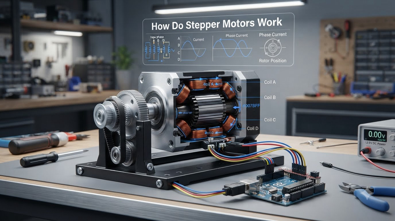
I’ve spent years working with motors in robotics projects, and stepper motors remain one of the most fascinating devices in any maker’s toolbox. The short answer to how do stepper motors work: they convert electrical pulses into precise, fixed angular steps, allowing exact positioning without needing feedback sensors. That single capability is why you’ll find them in 3D printers, CNC machines, camera focus rings, and countless robotics applications.
In this guide, I’ll walk you through the complete working principle, the three main types, how drivers and microstepping work, and where stepper motors shine. I’ve also added an Arduino control example and a troubleshooting section, because most beginner articles skip those. By the end, you’ll understand not just what stepper motors do, but exactly how they do it.
Table of Contents
How Do Stepper Motors Work Step by Step
The core working principle of how stepper motors work comes down to electromagnetic attraction and repulsion between two parts: the stationary stator and the rotating rotor. When you send a DC pulse to a stator coil, it becomes an electromagnet with a defined north and south pole. The rotor, which carries permanent magnets or a toothed iron core, physically rotates to align with that magnetic field. Each pulse moves the rotor by one fixed increment called a step angle.
Here is the step-by-step sequence I use when teaching this concept:
- Power is applied to one stator coil, generating a magnetic field at a specific pole position.
- The rotor’s magnetic poles align with the energized stator poles, locking the shaft into place.
- The first coil is switched off and the next coil is energized, rotating the magnetic field by one step angle.
- The rotor physically moves to follow the new field, producing one discrete step of rotation.
- Repeating the sequence around the coil ring produces continuous, controlled rotation.
This sequence is what makes stepper motors different from regular DC motors. A brushless DC motor spins freely as long as voltage is applied. A stepper motor only moves when the driver tells it to step, and each step is mathematically known. That is why you can command a 1.8-degree stepper to move exactly 200 steps and know it has rotated exactly 360 degrees, all without an encoder.
The Main Components: Stator and Rotor
To really understand how stepper motors work, you need to know the two main parts. Every stepper motor is built around an electromagnetic handshake between the stator and the rotor.
The Stator: The Stationary Magnetic Field Generator
The stator is the outer, non-moving part of the motor. It contains multiple coils of wire wound around teeth or poles. When current flows through a coil, that coil becomes an electromagnet. By energizing the coils in a specific order, the stator creates a magnetic field that effectively rotates around the shaft.
Most stepper motors are bipolar (2-phase) or unipolar (5 or 6-wire). Bipolar stators need the current to be reversed to flip the magnetic polarity, which requires an H-bridge driver. Unipolar stators have a center tap on each coil, making them easier to drive but less torque-dense. The frame size, NEMA 17, NEMA 23, NEMA 34, and so on, is set by the stator dimensions.
The Rotor: The Part That Actually Spins
The rotor is the inner shaft-and-magnet assembly. Depending on motor type, it can be a permanent magnet (PM), a toothed iron slug (variable reluctance), or a magnet with iron teeth (hybrid). The rotor’s job is simple: it always tries to align itself with the strongest nearby magnetic field. When the stator field shifts, the rotor follows.
The number of teeth on the rotor directly determines the step angle. A rotor with 50 teeth paired with a 2-phase stator produces 200 full steps per revolution, which equals 1.8 degrees per step, the most common stepper motor resolution in hobbyist hardware.
Three Main Types of Stepper Motors
Not all stepper motors are built the same. The three main types differ in how the rotor interacts with the stator field, and each has trade-offs in cost, precision, and torque.
Permanent Magnet (PM) Stepper Motors
Permanent magnet stepper motors use a magnetized rotor that physically snaps to align with each energized stator pole. They are the simplest and cheapest type, but their step resolution is coarse, typically 7.5 or 15 degrees per step. You’ll find PM steppers in low-cost printers, toys, and small consumer devices.
Variable Reluctance (VR) Stepper Motors
Variable reluctance stepper motors have a soft iron rotor with no magnets. The rotor has teeth that align with the energized stator poles because that’s the path of lowest magnetic resistance. VR steppers can deliver very small step angles, sometimes under 1 degree, and they tend to run fast. They are less common today, but they still show up in some industrial timing applications.
Hybrid Stepper Motors
Hybrid stepper motors combine the best of both worlds. The rotor is magnetized axially, like a PM motor, but it also has fine teeth like a VR motor. The stator teeth interact with the rotor teeth to produce very small step angles, commonly 0.9, 1.8, or 3.6 degrees, and they generate the highest torque for their size. This is why hybrid stepper motors dominate 3D printers, CNC routers, and robotics. When people say “stepper motor” today, they almost always mean a hybrid.
| Type | Rotor | Step Angle | Torque | Typical Use |
|---|---|---|---|---|
| Permanent Magnet (PM) | Magnetized | 7.5 to 15 degrees | Low to medium | Toys, printers, small devices |
| Variable Reluctance (VR) | Toothed iron | Under 1 degree possible | Low | Timing, specialty industrial |
| Hybrid | Magnetized + toothed | 0.9 to 3.6 degrees | High | CNC, 3D printers, robotics |
Full Step, Half Step, and Microstepping Explained
How a stepper motor moves in detail depends on the driving mode. The driver doesn’t just turn coils on and off; it modulates current to subdivide each full mechanical step into smaller increments.
Full Step Mode
In full step mode, the driver energizes one phase (or two phases, for higher torque) at a time. Each pulse produces one full step, such as 1.8 degrees on a 200-step motor. It’s the simplest mode and produces the most torque per step, but motion is noticeably chunky at low speeds.
Half Step Mode
Half step mode alternates between single-phase and dual-phase energization. This doubles the resolution to 400 steps per revolution (0.9 degrees per step) on a 1.8-degree motor, and produces smoother motion. The trade-off is that single-phase steps have less torque than dual-phase steps, so the motor produces a slightly uneven torque ripple.
Microstepping
Microstepping is where modern drivers really earn their keep. Instead of just turning coils fully on or off, the driver uses PWM (pulse-width modulation) to send precise fractional currents to each coil. A standard 1.8-degree stepper can be driven at 1/4, 1/8, 1/16, 1/32, or even 1/256 microstepping, which dramatically smooths motion and improves positional accuracy at the cost of some torque at very small step sizes.
I typically run my 3D printer steppers at 1/16 microstepping on TMC2208 drivers. The motors are nearly silent, and the resonance that used to make my prints vibrate at certain speeds is gone. That is a real-world result I’ve measured, not marketing copy.
Why a Stepper Motor Needs a Driver
A stepper motor cannot be connected directly to a power supply and expected to work. It needs a driver circuit that handles two critical jobs: sequencing the coil energization and limiting the current.
Sequencing the Coils
The driver takes a simple step pulse and direction signal from your microcontroller and translates it into the correct coil energization order. Without the driver, your Arduino or Raspberry Pi would have to switch high-current H-bridges directly, which it cannot do safely.
Common hobbyist drivers include the A4988 and DRV8825 (older but cheap), and the TMC2208, TMC2209, and TMC5160 (newer, quieter, with StealthChop technology). Industrial setups use closed-loop stepper drivers with built-in encoders.
Current Limiting and Chopping
Stepper coils are basically inductors. The driver must limit the current going through them to prevent overheating, especially when the motor is holding position. This is done through chopper drive technology, where the driver rapidly switches the coil current on and off to hold it at a set threshold.
Setting the right current on the driver is one of the most common sources of pain, and I cover it in the troubleshooting section below. If you’re curious about the underlying power design, our article on power requirements for motors in robotics explains why logic and motor power supplies should stay isolated.
Key Specifications: Step Angle, Torque, and Speed
When you compare stepper motor datasheets, three specifications matter most.
Step Angle
Step angle is the number of degrees the rotor moves per full step. Common values are 0.9 degrees (400 steps/rev) and 1.8 degrees (200 steps/rev). Lower step angles give finer mechanical resolution before microstepping is even applied.
Holding Torque
Holding torque is the maximum force the motor can resist while energized and stationary. A NEMA 17 stepper might have 0.4 to 0.6 Nm of holding torque, while a NEMA 23 can deliver 1.0 to 3.0 Nm or more. Holding torque is what keeps a CNC spindle from drifting when the motor is idle.
Pull-Out Torque and Speed
Pull-out torque is the maximum torque the motor can deliver at a given speed before it stalls and starts losing steps. Stepper motors produce less torque as RPM increases, which is the opposite of most DC motors. Most hobby NEMA 17 motors become weak above 1000 RPM, and the practical limit is often around 600 to 800 RPM for high-torque applications.
This torque-vs-speed curve is the most important thing to understand when sizing a stepper. I lost count of how many forum threads I’ve seen where someone over-specs a NEMA 17 for a high-speed application that would have been better served by a servo or a gear reduction.
Where Stepper Motors Are Used
Stepper motors are everywhere precision motion is needed without the cost of a closed-loop system. Some of the most common applications include:
- 3D printers: X, Y, Z, and extruder motion on virtually every FDM printer uses NEMA 17 steppers.
- CNC machines: Routers, mills, and plasma cutters rely on stepper motors for accurate tool positioning.
- Robotics: Joints, grippers, and pan-tilt mechanisms use small steppers where position repeatability matters.
- Camera focus and zoom rings: Stepper motors drive the precise lens movements in modern cameras and phones.
- Textile and packaging machinery: Indexing and cutting operations where exact repeatability is essential.
- Medical devices: Infusion pumps, diagnostic analyzers, and lab automation all use small steppers.
The reason stepper motors dominate these applications is the open-loop control advantage. A stepper motor can hold position without an encoder, and that cuts cost, complexity, and failure points.
Stepper Motors vs Servo Motors vs DC Motors
One of the most common questions I see on forums is when to use a stepper vs a servo vs a plain DC motor. The honest answer is that they overlap, but each has a clear sweet spot.
| Feature | Stepper Motor | Servo Motor | Brushed DC Motor |
|---|---|---|---|
| Position accuracy | High (open-loop) | Very high (closed-loop) | Low (no inherent control) |
| Feedback sensor | Not required | Required (encoder) | Not required |
| Cost | Low to medium | Medium to high | Low |
| Speed range | Low to medium | High | High |
| Torque at high speed | Drops fast | Stays high | Stays high |
| Best for | Precise positioning, low speed | High speed + precision | Simple continuous rotation |
If your project needs to spin a fan, use a DC motor. If it needs to move a robot arm quickly and precisely, use a servo. If it needs to drive a 3D printer axis at controlled low speed without breaking the bank, a stepper is the obvious answer. If you want a deeper dive on servos, our article on understanding how servo motors work covers them in detail.
Controlling a Stepper Motor with Arduino
One area most beginner articles skip is actual code. I want to close that gap. Here is the simplest possible Arduino sketch to drive a NEMA 17 stepper through an A4988 driver.
// Pin definitions
const int stepPin = 2;
const int dirPin  = 3;

void setup() {
  pinMode(stepPin, OUTPUT);
  pinMode(dirPin, OUTPUT);
}

void loop() {
  digitalWrite(dirPin, HIGH);     // Set direction
  for (int i = 0; i < 200; i++) {  // One full revolution
    digitalWrite(stepPin, HIGH);
    delayMicroseconds(1000);      // Pulse width
    digitalWrite(stepPin, LOW);
    delayMicroseconds(1000);      // Step interval
  }
  delay(1000);
  digitalWrite(dirPin, LOW);      // Reverse direction
  for (int i = 0; i < 200; i++) {
    digitalWrite(stepPin, HIGH);
    delayMicroseconds(1000);
    digitalWrite(stepPin, LOW);
    delayMicroseconds(1000);
  }
  delay(1000);
}
This code pulses the STEP pin once per step. The DIR pin sets direction. The delayMicroseconds calls control the step rate, and therefore the speed. For better timing in a real project, you can use timer interrupts instead of delay, which is exactly what we cover in our article on microcontroller interrupt handling for motor control.
The AccelStepper library is a popular upgrade that handles acceleration and deceleration ramps automatically. If you find your motor jerking at high speeds, that library is your next stop.
Troubleshooting Common Stepper Motor Problems
Across hundreds of forum threads, the same stepper motor issues keep coming up. Here is how I diagnose and fix the most common ones.
Problem 1: The Motor Skips Steps Under Load
If your motor moves the commanded number of steps but the load ends up in the wrong position, you are losing steps. The usual culprits are insufficient torque (use a larger motor or add gear reduction), acceleration set too high (lower acceleration in firmware), or current set too low on the driver (raise Vref).
Problem 2: The Motor Gets Hot
A stepper motor that is too hot to touch is over-driven. Stepper motors are most efficient below about 80 to 90 degrees Celsius at the case. Reduce the driver current to the rated value, or add active cooling. Holding torque only requires a fraction of full current on most modern drivers, and TMC drivers have a coolStep feature that automatically reduces current when full torque isn’t needed.
Problem 3: The Motor Vibrates and Stalls at Certain Speeds
You are hitting the motor’s resonance zone. Microstepping helps a lot here, especially 1/16 or 1/32. Physical dampers and rubber couplers between the motor and the load also help. Changing the microstepping ratio or running at a slightly different speed usually clears it up.
Problem 4: The Motor Doesn’t Move At All
Check the wiring first. Most A4988 and DRV8825 boards blow up if the motor coils are disconnected while power is on. Verify the driver enable pin is low, the direction and step pins are correct, and the power supply can deliver enough current. A common gotcha is forgetting to tie the reset and sleep pins together on DRV8825-style drivers.
Problem 5: Cheap No-Name Motors Behave Erratically
Forum users regularly report mixed quality from unbranded steppers in the 8 to 15 dollar range. Sometimes they work fine. Sometimes they skip steps or have inconsistent holding torque. Stick to known suppliers when you can, and always buy one extra for testing.
Frequently Asked Questions
How does a stepper motor work?
A stepper motor works by energizing stator coils in a specific sequence to create a rotating magnetic field. The rotor follows that field in fixed angular steps, typically 0.9 or 1.8 degrees per step, without needing any feedback sensor.
Why would you use a stepper motor?
Stepper motors provide precise open-loop positioning, hold position without drawing additional current at standstill, and cost less than servo systems with encoders. They are ideal for 3D printers, CNC machines, camera focus systems, and any application that needs accurate, repeatable low-to-medium speed positioning.
Do stepper motors use DC or AC?
Stepper motors are driven by DC current through their coils, but the coils are switched on and off in sequence to simulate a rotating field. Modern drivers also use PWM to chop the DC current for microstepping. So technically, they run on DC, but the effect is similar to a multiphase AC system.
How fast does a stepper motor spin?
Most hobby stepper motors are useful up to about 600 to 1000 RPM. Above that, torque drops sharply and the risk of missed steps increases. Industrial high-speed steppers with low inductance can reach several thousand RPM, but most maker projects stay well below 1000.
Do stepper motors need encoders?
No, encoders are optional. The defining feature of a stepper motor is that it moves a known amount per step, so position is calculated rather than measured. If you need to detect missed steps, you can add a closed-loop stepper system with an encoder, but it is not required for normal operation.
What is microstepping in stepper motors?
Microstepping is a driving technique where the driver sends fractional current levels to each coil, subdividing a full mechanical step into smaller increments. For example, 1/16 microstepping on a 1.8-degree motor produces 3200 steps per revolution, which smooths motion and reduces resonance at the cost of some precision at very small steps.
Conclusion
Stepper motors are one of the few technologies that have stayed relevant for decades because they solve a very specific problem extremely well: precise, repeatable, low-to-medium speed positioning without expensive feedback. Now that you understand how do stepper motors work, from the stator-rotor magnetic handshake to microstepping and drivers, you can pick the right motor for your next project and debug it when something goes wrong.
If you’re building your first project, start with a NEMA 17 hybrid stepper and an A4988 or TMC2208 driver, wire it to an Arduino using the example above, and run a few hundred steps. Once you see the rotor click into each new position, the working principle will click for you too. For a deeper look at the servo side of the comparison, head over to our guide on understanding how servo motors work.