
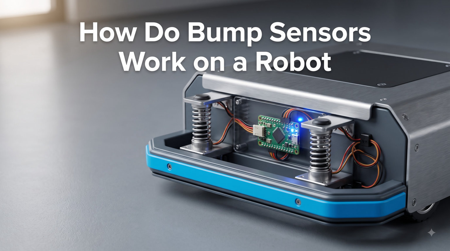
When I first wired a micro-switch to a small Arduino car, the robot stopped ramming into my bookshelf legs and started pivoting away. That moment is exactly what this guide is about: how do bump sensors work on a robot, and how a few dollars of hardware can give a machine the gift of “feeling” a wall before it grinds gears.
You’ll get a clear definition for featured snippets, a walk-through of the underlying mechanism, a comparison of the three main sensor types, an Arduino wiring walkthrough, and the calibration tricks our team uses to kill false triggers. If you’re building anything from a maze solver to a robot vacuum, the answers below will save you hours of trial and error.
Table of Contents
What Is a Bump Sensor on a Robot
A bump sensor is a switch-based device that detects physical contact between a robot and an obstacle, then sends a signal so the robot can react. In practice, it is usually a micro-switch, an IR-reflective pair, or a conductive element that closes a circuit the moment the robot’s bumper touches something.
Think of it as the robot’s fingertips. A camera “sees” and an ultrasonic sensor “hears” a wall from a distance, but a bump sensor only fires when the chassis actually meets resistance. That makes it one of the cheapest, most reliable forms of contact detection in robotics, and a staple in everything from classroom Arduinos to industrial AGVs.
For broader context on how these sensors bolt onto the frame they protect, our robot chassis guide walks through the structural side. The short version: bump sensors live at the front edge of the chassis so the bumper hits first.
How Do Bump Sensors Work on a Robot
Bump sensors work by completing or breaking an electrical circuit when contact occurs. A microcontroller like an Arduino constantly monitors that circuit, and the moment its state flips from open to closed (or vice versa), the robot knows it has bumped into something.
Here is the signal path our team traces every time we debug a bumper:
- The robot drives forward with the sensor circuit in a known “rest” state, usually HIGH thanks to a pull-up resistor.
- The bumper makes contact with an obstacle and physically deflects.
- That deflection closes (or opens) a switch contact inside the sensor.
- Voltage at the sensor’s output pin changes from one logic level to the other.
- The microcontroller reads the digital pin, runs a short debounce routine, and triggers a turn, reverse, or stop routine.
The “rest” value matters. Most beginner projects use a 10k pull-up resistor, which holds the input at 5V (HIGH) when nothing is touching. When the bumper pushes the switch closed, the pin drops to LOW. Other designs flip this and use a pull-down resistor instead; both are valid, but you need to match your code to the wiring.
Why This Simple Idea Still Wins
IR and ultrasonic sensors are smarter, but they fail on transparent, dark, or angled surfaces. A bump sensor does not care about color, transparency, or material. It is also nearly immune to ambient light and electrical noise, which is why it survives on factory floors where vision systems get blinded by sparks and dust.
Types of Bump Sensors Used in Robotics
There are three families of bump sensors you’ll see in hobby and commercial robots. Each solves the same problem with a different mechanism, and each has tradeoffs that show up in the data.
| Type | How It Detects Contact | Response Time | Best For | Common Pitfall |
|---|---|---|---|---|
| Mechanical (micro-switch) | Spring-loaded contacts close when bumper deflects | Under 5 ms | Reliable contact detection, low cost | Mechanical wear over millions of cycles |
| IR-based bump sensor | IR LED and photodiode detect change in reflected light on contact | 1-10 ms | Non-contact proximity plus contact trigger | Spurious detections from sunlight and shiny surfaces |
| Resistive (conductive foam, flex sensor) | Resistance changes when material compresses or bends | 5-20 ms | Soft robotics, curved bumpers, force sensing | Calibration drift and temperature sensitivity |
Mechanical Micro-Switch Bumpers
A micro-switch is the workhorse of beginner robotics. A small spring-loaded lever sits behind the bumper; press the bumper, and two metal contacts snap together. They are cheap (often under a dollar), handle millions of cycles, and output a clean digital signal. Most of the bump sensors you see on Pololu, Romi, and Arduino robot kits are micro-switches with a whisker or paddle attached.
IR-Based Bump Sensors
IR bump sensors add an LED and a phototransistor inside the bumper. When the bumper touches an obstacle, the gap between the sensor and the target shrinks, and the reflected IR light intensity jumps. The sensor’s comparator output flips, and the microcontroller sees a digital edge. The benefit is dual-mode sensing: you get a proximity signal as the robot approaches, plus a hard contact trigger when it finally bumps.
Resistive and Conductive Bump Sensors
Conductive foam, velostat, and flex sensors change resistance when pressed or bent. They are popular in soft robotics and curved bumpers where a rigid micro-switch would not fit. The tradeoff is that the signal is analog, not digital, so you need an ADC pin and a calibration routine to map resistance to “bumped / not bumped.”
How to Connect a Bump Sensor to Arduino
Wiring a bump sensor to an Arduino takes about ten minutes once you have the parts. Our team uses this exact recipe for classroom builds and quick prototypes.
Step 1: Gather the Components
- Arduino Uno (or Nano, Mega, any board with digital input pins)
- Micro-switch or pre-built bump sensor module
- 10k ohm pull-up resistor (only if you’re wiring a bare switch)
- Jumper wires and a small breadboard
Step 2: Wire the Circuit
Connect one leg of the switch to Arduino 5V. Connect the other leg to digital pin 2. Place a 10k resistor between digital pin 2 and GND. This is your pull-down; when the switch is open, the pin reads LOW. When the switch closes, 5V flows through and the pin reads HIGH.
You can also wire it the other way around (switch to GND, pull-up resistor to 5V) and flip the logic in your code. Both approaches are common; just stay consistent.
Step 3: Write the Read Routine
In your sketch, set the sensor pin as INPUT, then read it inside loop(). When the value changes, run a 20-50 ms debounce delay, then re-read to confirm the bump is real. This kills the false triggers that forum users complain about from vibration and switch bounce.
Step 4: React to the Bump
Once the bump is confirmed, your code can stop the motors, reverse for 200 ms, then turn 90 degrees and resume driving. That simple behavior-reaction loop is the basis of every wall-following and maze-solving algorithm.
Common Applications of Bump Sensors
Bump sensors show up wherever a robot needs to survive contact. A few examples our readers build most often:
- Maze-solving robots: Two front bump sensors plus left/right whiskers give full 360-degree awareness for flood-fill or wall-following algorithms.
- Robot vacuums: A ring of micro-switches under the bumper triggers an immediate reverse-and-rotate when the unit hits a chair leg.
- Line-following robots: Bump sensors add a safety layer so a misaligned IR line follower does not push the robot off the table.
- Industrial AGVs: Heavy-duty bumpers act as both the safety stop and a hardware-level E-stop when the warehouse Wi-Fi drops.
- STEM classroom kits: The cheapest, most teachable sensor because the wiring and code fit on a single breadboard.
Calibration and Troubleshooting Tips
Bump sensors are simple, but they break in predictable ways. These are the fixes our team reaches for first.
Killing False Triggers
Vibration is the number-one cause of phantom bumps. Tighten the bumper mount so it does not rattle, and add a 20-50 ms software debounce. If false triggers still appear, the switch may be mounted too close to a vibrating motor; add a foam gasket or move it forward.
Picking the Right Resistor Value
Forum users on r/arduino and robotics.stackexchange consistently report 10k ohms as the sweet spot for pull-up and pull-down resistors on bare switches. Go lower (1k-4.7k) if your wire runs are long and you are picking up noise. Go higher (47k-100k) for battery-powered builds where you want to minimize current draw through the divider.
Debouncing Switch Bounce
Mechanical switches do not transition cleanly. They bounce for a few milliseconds. In hardware, a 0.1 microfarad capacitor across the switch smooths the bounce. In software, ignore any state change shorter than 20-30 ms. Doing both is even better.
How Many Sensors Do You Need
Eight sensors is a common upper limit for full 360-degree coverage, with most hobbyists starting with 2-3 front sensors. Adding more sensors means more wiring, more debounce logic, and more chances for false triggers, so only add them when the robot’s blind spots actually cause problems.
IR Sensor Spurious Detections
IR bump sensors fire when reflected light jumps, which can happen from sunlight, glossy floors, or even the robot’s own shadow. Shield the LED and photodiode inside a small tube, calibrate against the floor material, and always combine IR with a mechanical switch for a hard contact backup.
Advanced Bump Sensor Materials and Designs
Once the basics are working, makers start experimenting with new materials. Conductive foam wrapped around a bumper becomes a single large contact sensor; velostat and copper tape create bend-sensitive skins; and flexible tubes with internal pressure sensors give force-feedback bumpers used in soft robotics research.
These designs matter because rigid micro-switches struggle on curved or compliant robots. A foam bumper can sense not just that contact happened, but roughly where along its length, which is something no single micro-switch can do. If you are building a soft-gripper or a humanoid, the resistive path is worth the extra calibration effort.
Frequently Asked Questions
What does a bumper sensor do?
A bumper sensor detects physical contact between a robot and an obstacle and signals the robot’s controller so it can stop, reverse, or turn. Most use a micro-switch that closes a circuit on impact, sending a digital HIGH or LOW signal to the microcontroller.
How are sensors used in robotics?
Sensors give robots information about their environment. Bump sensors detect contact, ultrasonic and IR sensors measure distance, gyroscopes track rotation, and cameras identify objects. Together, these inputs let a robot navigate, avoid obstacles, and complete tasks without constant human input.
Can bump sensors detect obstacles before physical contact?
Standard mechanical bump sensors only fire on contact, but IR-based bump sensors can detect obstacles a few millimeters away by sensing reflected light. Combining a mechanical switch with an IR pair gives both proximity warning and confirmed contact in one bumper.
How many bump sensors does a robot need?
Most beginner robots use two or three front-facing sensors, while full-coverage builds use up to eight sensors around the chassis. Start with the minimum needed to cover the robot’s blind spots and add more only when navigation behavior demands it.
What resistance value should I use with a bump sensor on Arduino?
A 10k ohm pull-up or pull-down resistor is the standard starting point for a bare micro-switch on Arduino. Lower values (1k to 4.7k) help reject noise on long wire runs, while higher values (47k to 100k) reduce current draw on battery-powered builds.
Final Thoughts on Robot Bump Sensors
So, how do bump sensors work on a robot? A simple switch or reflective pair closes a circuit on contact, and a few lines of Arduino code turn that signal into stop, reverse, and pivot behavior. They are cheap, fast, and reliable, which is why every serious robotics kit ships with at least one.
If you are just starting out, wire a single micro-switch to your robot, add a 10k resistor, and write a debounced read routine. Once that works, experiment with IR pairs for proximity warning and conductive foam for force feedback. Each step teaches a different layer of how robots sense the physical world.