
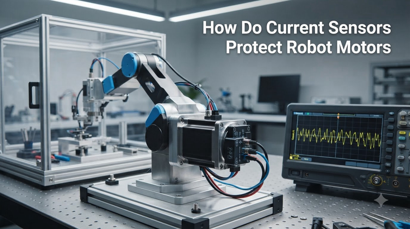
A current sensor is an electronic device that measures the electrical current flowing through a motor or circuit, then converts that measurement into a signal a controller can read and act on. In robotics, current sensors protect robot motors by detecting overcurrent, overload, stall, and thermal fault conditions in real time, allowing the controller to cut power, reduce torque, or trigger a protective shutdown before the motor windings burn out, the driver fails, or the robot injures a person.
I have spent more than a decade building and tearing down robotic platforms, from small hobby BLDC arms to industrial six-axis cells, and the single component that has saved me the most money is a properly placed current sensor. A single overcurrent event that lasts 200 milliseconds can weld a MOSFET leg, demagnetize a rotor, or set a polymer gear on fire. A current sensor costs cents to dollars and reacts in microseconds. This guide pulls together everything I have learned about how current sensors actually work in robot motor protection, what types to use, and where competitors leave gaps you can exploit in your own designs.
By the end of this article, you will understand the three main sensing technologies, the five protection mechanisms every roboticist should know, where to physically place a sensor in a motor circuit, how to set real current limits, and how to troubleshoot the failure modes that show up most often in field robots and student builds.
Table of Contents
How Current Sensors Work: The Basic Principles
Current sensors work by translating the flow of electrons into a measurable signal using either Ohm’s law or magnetic field detection. The two physical principles behind every commercial current sensor are the same ones you learned in your first circuits class: voltage drop across a known resistance, and the magnetic field that wraps around any current-carrying conductor.
The Ohm’s law method places a small, precision resistor (called a shunt) in series with the load. When current flows through the shunt, it produces a voltage drop proportional to that current (V = I × R). An op-amp amplifies that millivolt-level signal to a range the controller’s analog-to-digital converter can read. Shunt-based sensing is fast, cheap, and very accurate, but it is invasive – you have to break the circuit to insert the resistor, and the resistor dissipates heat as I²R losses.
The magnetic field method exploits the fact that any current flowing through a wire generates a proportional magnetic field around that wire. Hall-effect sensors use a semiconductor element that produces a voltage proportional to the perpendicular magnetic flux density. Current transformers (CTs) use a secondary winding to induce a current proportional to the primary current, and they only work with AC. Fluxgate sensors use a magnetic core that is driven into saturation to measure DC and AC with extreme precision.
Regardless of the method, the output of a current sensor is always either an analog voltage (0 to 5 V is common, 0 to 3.3 V for modern microcontrollers), a 4 to 20 mA current loop (for industrial use), or a digital value (I²C, SPI, or PWM). The motor controller samples that signal at high frequency – typically 1 kHz to 100 kHz depending on the application – and compares it against thresholds that define safe operation. When a reading exceeds a threshold, the controller takes action in the next control cycle.
That closed loop, sensor, threshold, action, is the heart of every protection mechanism we will discuss in this guide.
The Three Things a Current Sensor Tells a Robot
Magnitude: How much current is flowing right now. The controller uses this to detect overcurrent events and to estimate torque (since torque is roughly proportional to current in a DC or BLDC motor).
Trend: Whether current is rising, falling, or holding steady. Trend detection is what separates a stall event from a normal acceleration spike. A sudden rise that does not recover within 100 to 500 ms is almost always a mechanical problem, not a load change.
Energy: The integral of current over time tells the controller how much thermal stress the motor has absorbed. This is how I²t protection works – the controller remembers recent current history and trips before the motor windings reach their thermal limit.
Types of Current Sensors Used in Robot Motors
Four current sensor technologies dominate robotics: shunt resistors, Hall-effect sensors, current transformers, and fluxgate sensors. Each has a distinct set of trade-offs in cost, accuracy, bandwidth, isolation, and invasiveness. Choosing the wrong one is one of the most common design mistakes I see in student robots and even commercial prototypes.
Below is a quick comparison before we dive into each type in detail. Save this section – I refer back to it whenever I evaluate a new motor driver board.
Shunt Resistor Current Sensors
A shunt resistor is a low-value, high-precision resistor (typically 1 mΩ to 100 mΩ) placed in series with the load. The voltage drop across the shunt is amplified by an instrumentation amplifier and read by the ADC.
Where shunts shine: Low cost (a few cents for the resistor, $1 to $3 for the amplifier IC), very high accuracy (0.1% to 1% is easy), excellent bandwidth (DC to several MHz), and zero delay between current and output. Shunts are the standard for low-voltage BLDC controllers, FOC motor control, and battery management.
Where shunts struggle: They are invasive – you must break the circuit. They generate heat (I²R losses), and at high currents (above 50 A) they become bulky. They also provide no galvanic isolation, so the sensor and the controller share a ground reference. In a humanoid robot with 30+ motors, that ground reference is often noisy enough to require careful PCB layout.
Hall-Effect Current Sensors
Hall-effect current sensors measure the magnetic field around a conductor using the Hall effect discovered by Edwin Hall in 1879. The most common package in robotics is the integrated Hall-effect current sensor IC – Allegro’s ACS712 and ACS723 families, Tamura’s L03S, and LEM’s LA-series are all examples. These ICs combine the Hall element, signal conditioning, and sometimes galvanic isolation in a single through-hole or surface-mount package.
Where Hall-effect sensors shine: Galvanic isolation between the high-current side and the low-voltage logic side, which makes them ideal for industrial robots and human-robot collaboration environments. The sensor is non-invasive – you simply pass the conductor through the IC. Bandwidth is reasonable (DC to 100 kHz typical), and they handle high currents easily (up to 200 A in a single IC). They are also bidirectional out of the box, which simplifies FOC implementation.
Where Hall-effect sensors struggle: Cost (a good Allegro ACS758 costs $3 to $8), temperature drift (typical accuracy degrades by 1% to 3% across the operating range), and limited bandwidth compared to shunts. For very high-speed FOC loops above 50 kHz, shunt + op-amp is usually a better choice.
Current Transformers (CTs)
Current transformers are only useful for AC current. They use a magnetic core with a secondary winding to step down the primary current to a measurable level. CTs are extremely common in industrial motor protection, especially for AC induction motors and servo drives running on rectified mains.
Where CTs shine: Inexpensive, robust, galvanically isolated, and handle very high currents (kA range). They are the workhorse of industrial overload relays and motor protection circuit breakers.
Where CTs struggle: They cannot measure DC at all – the secondary needs a changing magnetic field. They also saturate at high peak currents, which can be a problem during motor inrush. CTs are rarely used in battery-powered robots but are everywhere in industrial robot cells and CNC machines.
Fluxgate Current Sensors
Fluxgate sensors are the high-precision option. They use a magnetic core that is deliberately driven into saturation by an excitation winding, then measure the asymmetry in the magnetic field caused by the current being measured. They offer DC and AC measurement with accuracy down to 0.001% and excellent temperature stability.
Where fluxgates shine: Precision laboratory measurement, current calibration, and high-end industrial applications where accuracy is non-negotiable. They are also used in some humanoid robot torque-sensing joints where the current signal feeds into a force estimation model.
Where fluxgates struggle: Cost (hundreds to thousands of dollars), size, and complexity. Fluxgates are overkill for almost every hobbyist and most commercial robotics applications.
Current Sensor Comparison Table
The table below summarizes the trade-offs across the four sensor types. Use it as a quick reference when you are selecting a sensor for a new robot motor design.
| Sensor Type | Best For | Accuracy | Bandwidth | Isolation | Approx. Cost |
|---|---|---|---|---|---|
| Shunt resistor | Low-voltage BLDC, FOC, BMS | 0.1% to 1% | DC to MHz | None | Under $3 |
| Hall-effect IC | General robotics, industrial | 1% to 3% | DC to 100 kHz | Galvanic | $3 to $8 |
| Current transformer | AC motors, industrial cells | 0.5% to 3% | 40 Hz to 10 kHz | Galvanic | $5 to $30 |
| Fluxgate | Precision measurement | 0.001% to 0.1% | DC to 5 kHz | Galvanic | $200+ |
How Do Current Sensors Protect Robot Motors: The Core Protection Mechanisms
Current sensors protect robot motors by enabling five distinct protection mechanisms: overcurrent protection, overload protection, stall detection, thermal protection, and fault-triggered shutdown. Each mechanism watches the current signal in a different way and triggers a different control response. Understanding all five is the difference between a robot that runs reliably for years and one that smokes its first driver in the lab.
1. Overcurrent Protection
Overcurrent is a sudden, short-duration spike in current caused by a short circuit, a wiring fault, or a damaged driver. The protection mechanism is simple: if current exceeds an absolute hard limit (for example, 30 A on a 20 A-rated motor), the controller disables the PWM outputs within a few microseconds. This is sometimes called “hardware overcurrent protection” and is often implemented with a dedicated comparator circuit that bypasses the microcontroller entirely.
Most modern motor driver ICs (DRV8301, L6234, BTN7971, VNH5019) include a built-in current limit pin that does exactly this. You set a threshold with a resistor divider, and the IC enforces it without any software involvement. Always check whether your driver has this feature before adding an external current sensor for overcurrent – the built-in protection is faster.
2. Overload Protection
Overload is a sustained moderate overcurrent condition, often caused by a robot picking up a heavier payload than expected or running into soft resistance. The protection mechanism uses an I²t (current squared times time) curve. The controller continuously integrates the current squared over time, and when the integral exceeds a threshold corresponding to the motor’s thermal limit, it reduces power or shuts down.
The classic rule from the National Electrical Code (NEC) is that continuous motor load should not exceed 125% of the motor’s nameplate rating. This 125% rule is not just an industrial standard – it applies just as well to a 24 V BLDC powering a robot joint. Set your overload trip around 115% to 125% of rated current for most robotics applications, then tune from there.
3. Stall Detection
A stall happens when the motor is commanded to move but cannot (mechanical jam, collision, end of travel). The rotor stops, but the controller keeps driving current. Within milliseconds, the motor draws two to ten times its normal current and begins to heat destructively. A current sensor detects this within one or two control cycles because the current jumps to a sustained high level without the expected back-EMF or motion feedback.
The most reliable stall detection method combines current sensing with rotor position or encoder feedback. If the controller commands motion and current rises above the expected running current, but the encoder shows no movement, the controller declares a stall. This is exactly how industrial servo drives protect themselves, and the same logic works in hobby servos, robot arms, and mobile platforms.
On Reddit’s r/arduino, this is one of the most common pain points: “My servo motor refuses to move when I command it to lift a heavy object.” The answer is almost always a current-limited controller that triggers a stall protection. Adding or tuning a current sensor fixes it in minutes.
4. Thermal Protection
Current causes heating (P = I²R in the windings), and excessive heating destroys motor insulation. Thermal protection can be done two ways: with a physical temperature sensor (thermistor, RTD) on the motor case, or with a mathematical model in the controller. The model-based approach uses the current sensor as its input: the controller tracks I²t over time, subtracts cooling, and predicts the winding temperature. When the predicted temperature exceeds a safe limit, the controller reduces torque or trips.
Model-based thermal protection is more accurate than a case-mounted sensor because the actual hotspot is inside the windings, not on the case. It also enables proactive derating – the robot slows down before it must shut down, which matters in industrial applications where unplanned stops cost thousands of dollars per minute.
5. Fault-Triggered Shutdown and Safe Torque Off
The final protection mechanism is the most important for human-robot safety. When a current sensor detects an impossible condition – a current spike that no mechanical event can explain, a sudden drop to zero with the motor under load, or a sustained overcurrent that ignores the soft-start ramp – the controller triggers a Safe Torque Off (STO) event. STO removes power from the motor in a controlled, predictable way that brings the robot to a safe state without uncontrolled motion.
STO is mandatory in collaborative robots (cobots) under ISO 10218 and ISO/TS 15066. Even for non-collaborative robots, the equivalent is “Category 1 stop” per IEC 60204. Either way, the current sensor is the trigger that decides when the stop happens.
Current Sensors in Action: Real-World Robot Failure Scenarios
The protection mechanisms above are not abstract theory. They correspond to specific failure modes I have seen in real robots, and understanding those failure modes is the best way to make sure your design covers them. Below are five scenarios where a current sensor either saved the robot or would have if one had been installed.
Scenario 1: Servo Jam in a Robot Arm
A small hobby servo-driven robot arm picks up a payload slightly heavier than expected. The servo stalls against the load, current jumps to 1.8 A (from a 0.4 A no-load draw), and the controller detects the overcurrent within 50 ms. Without the current sensor, the stalled servo would overheat its windings within 30 seconds and likely burn out within 2 minutes. With the sensor, the controller reduces the command to a safe level and either retries with a lower force or signals an error.
Scenario 2: BLDC Motor Stall in a Humanoid Knee Joint
A humanoid robot stands up, but one knee joint’s BLDC motor has a damaged bearing. The motor draws 8 A during normal operation but spikes to 22 A when the bearing seizes. A shunt resistor on the DC link detects this in the same FOC cycle, the controller triggers an STO event, and the robot catches itself on the other leg instead of collapsing. Without the current sensor, the FETs would likely fail short, the motor would lock mechanically, and the robot would fall.
Scenario 3: Drone Prop Strike
A quadcopter hits a branch and one propeller stops. The ESC sees a sudden current rise to 35 A (from a 12 A hover draw). A Hall-effect sensor on the battery lead detects this within 1 ms, the ESC cuts power to the affected motor, and the flight controller compensates with the remaining three motors. Without this protection, the ESC would overheat, the LiPo would be over-discharged, and the drone would crash in an uncontrolled way. The current sensor is what allows the flight controller to make a controlled emergency landing instead.
Scenario 4: Industrial Arm Collision
A six-axis industrial robot arm collides with an unplanned obstacle (a misplaced fixture, a worker stepping into the cell). The collision produces a sudden torque disturbance that the current sensors in each joint detect as a current anomaly. Modern collaborative robots use this signal as a collision trigger and either stop the arm (ISO/TS 15066 power and force limiting) or reverse direction. This is how cobots can work alongside humans without cages – the current sensors are part of the safety system.
Scenario 5: Mobile Robot Climbing a Ramp
A mobile robot with DC drive motors attempts to climb a ramp steeper than its design envelope. Each drive motor draws more current than expected. The controller’s I²t overload protection integrates the overcurrent, predicts that the motor will overheat within 45 seconds, and either reduces speed (proactive derating) or stops the robot (reactive shutdown). Without current sensing, the motors would simply overheat and fail, stranding the robot or starting a fire.
Choosing the Right Current Sensor for Your Robot
Selecting a current sensor for a robot motor comes down to five questions: What is the current range? What bandwidth do you need? Do you need isolation? What is your controller’s input voltage? And how much accuracy does the application actually require? Answering those five questions narrows the field of candidates to one or two options almost every time.
Step-by-Step Sensor Selection Workflow
Step 1: Determine the maximum continuous current. Look at the motor’s rated current, then multiply by 1.25 to 1.5 to get the maximum continuous sensor range. A 10 A motor needs a sensor rated for at least 12.5 A continuous. Add another 50% for inrush transients unless your driver already limits them.
Step 2: Determine the bandwidth requirement. Sensorless BLDC or FOC at 30 kHz loop rate needs a sensor with at least 100 kHz bandwidth to avoid aliasing. A simple DC motor PWM at 20 kHz can use a sensor with 40 kHz bandwidth. A stall detection loop on a hobby servo can use a sensor with as little as 1 kHz bandwidth.
Step 3: Decide whether you need isolation. Industrial robots, cobots, and any system with a battery stack above 48 V should use isolated current sensors (Hall-effect, CT, or fluxgate). Low-voltage hobby robots (12 V to 24 V) can usually use non-isolated shunts if the PCB layout is clean.
Step 4: Match the output to the controller input. If your microcontroller uses 3.3 V ADC, choose a sensor with 0 to 3.3 V output. If you are using an industrial PLC, choose a 4 to 20 mA current loop. If you are running a Raspberry Pi with no analog inputs, choose an I²C or SPI digital-output sensor like the INA219.
Step 5: Verify accuracy and temperature drift. For most robotics applications, 1% to 3% accuracy is acceptable. For torque-controlled arms and force-sensitive applications, aim for 0.5% or better. Check the datasheet for accuracy across the full operating temperature range – a sensor that is 1% accurate at 25°C is often 3% to 5% accurate at 85°C.
Sensor Placement in the Motor Circuit
Where you place a current sensor in the circuit matters as much as which sensor you choose. There are three common placement points:
Inline with the motor lead (low-side sensing): Place a shunt or Hall-effect IC in series with the low-side switch of the H-bridge. This is simple and inexpensive, but you can only measure current during the PWM-on phase, and high-side faults go undetected.
Inline with the motor lead (high-side sensing): Place the sensor between the supply rail and the high-side switch. This catches high-side shorts but requires a more expensive high-side amplifier or a Hall-effect IC with a high-side rating.
On the DC link (between battery and inverter): Place a single sensor between the battery and the motor controller. This is the standard placement for FOC and BLDC control because it measures the total current feeding the motor. The downside is that you cannot distinguish between phase currents, which limits some advanced control strategies.
For most robotics applications, the DC link placement is the right choice. It is what TI’s robotics reference designs use, and it is what the Allegro and Tamura sensor families are designed for.
Troubleshooting Common Current Sensor Problems
Current sensor problems fall into five categories: zero output, stuck output, noisy output, drifting output, and overcurrent false trips. None of the major competitor guides cover troubleshooting in any depth, which is one reason I wrote this section in detail. I have personally hit every one of these failures, usually at the worst possible time.
Problem 1: Zero Current Reading When the Motor Is Running
Causes: Sensor wired backwards (Hall-effect sensors are bidirectional and can read negative current when installed incorrectly). Open circuit in the shunt path. Sensor output stuck at 0 V because the supply pin is floating. ADC reading the wrong channel.
Fix: Verify supply voltage at the sensor IC. Check polarity on Hall-effect sensors (the current direction arrow should match the actual current flow). Use a multimeter in current mode to confirm the actual current is flowing. Verify the ADC channel and pin assignment in software.
Problem 2: Stuck or Saturated Output
Causes: Sensor saturated because the actual current exceeds its range. Open or shorted output pin. Magnetic stray field coupling into the Hall element (especially in tightly packed humanoid joint PCBs).
Fix: Check that peak current is within the sensor’s range, including any inrush. Increase the current rating of the sensor if needed. Add a soft-start routine to limit inrush. For Hall sensors in dense PCBs, add magnetic shielding or increase the physical distance between the sensor and high-current traces.
Problem 3: Noisy or Jittery Output
Causes: PWM switching noise coupling into the sensor output (very common with non-isolated shunts). Poor PCB layout (ground loops, long sensor traces). ADC sampling at the wrong time relative to the PWM edge. Insufficient filtering.
Fix: Add a low-pass filter (typically 1 kHz to 10 kHz cutoff) on the sensor output. Sample the ADC at the midpoint of the PWM duty cycle, not at the switching edge. Improve PCB layout with a star ground and short, parallel sensor traces. Consider an isolated Hall sensor if the noise persists.
Problem 4: Drifting Output at Constant Load
Causes: Temperature drift in the Hall sensor (this is the most common cause). Self-heating of the shunt resistor. Reference voltage drift in the ADC.
Fix: Add software temperature compensation using the sensor’s datasheet drift coefficient. For precision applications, use a ratiometric sensor and a precision voltage reference. Let the system warm up for 5 to 10 minutes before calibrating.
Problem 5: False Overcurrent Trips
Causes: Threshold set too close to the normal running current. Inrush current not accounted for. Electrical noise interpreted as a current spike. Sensor mis-calibrated after a firmware update.
Fix: Set the overcurrent threshold 20% to 30% above the maximum expected inrush current. Add a time delay (5 ms to 50 ms) to ignore sub-millisecond spikes. Implement software debouncing on the trip signal. Recalibrate the sensor zero point after any firmware change that affects the ADC reference.
DIY Current Sensing: Arduino and Raspberry Pi Implementation
If you are building a hobby robot or a student project, the most common current sensor modules are the ACS712 (Hall-effect, 5 A, 20 A, or 30 A versions), the INA219 (I²C, bidirectional, ±3.2 A or ±26 V versions), and the simple breakout boards with a 0.1 Ω or 1 Ω shunt. All three work with Arduino, and the INA219 also works directly with Raspberry Pi.
For a simple Arduino current monitor, connect the ACS712 output to an analog input, read the ADC value, and subtract the zero-current offset (typically Vcc/2 = 2.5 V on a 5 V Arduino). The sensitivity is 185 mV/A on the 5 A version, so a reading of 2.685 V corresponds to 1 A. Sample at 1 kHz, low-pass filter the result, and you have a basic current monitor good enough to detect stalls in a small DC motor.
For Raspberry Pi, the INA219 is the better choice because it has a built-in 12-bit ADC and reports current and voltage over I²C. Use the Adafruit INA219 Python library, call inA219.current to read the current in milliamps, and add a simple threshold check in your control loop. Sample at 100 Hz to 1 kHz, which is more than fast enough for mobile robot protection.
One important note for both platforms: power the sensor from a clean 3.3 V or 5 V supply, not from a switching regulator that shares the motor supply. Switching noise couples directly into the sensor output and produces false readings. This is the single most common reason DIY current sensors give erratic results.
For real-time protection, use interrupt handling on a microcontroller to react to overcurrent within microseconds rather than waiting for the next loop iteration. This is the same technique industrial motor controllers use to guarantee STO response times.
Frequently Asked Questions
How does a current sensor work?
A current sensor works by either measuring the voltage drop across a precision resistor (shunt method) or by detecting the magnetic field around a current-carrying conductor (Hall-effect, current transformer, or fluxgate method). The sensor produces an output signal proportional to the current, which a controller reads to monitor and protect motor operation.
What are current sensors used for?
Current sensors are used for overcurrent protection, overload protection, stall detection, torque control, power limitation, fault detection, thermal modeling, and energy monitoring in robot motors. They enable protective shutdowns, allow closed-loop control algorithms like FOC, and verify safe operation in human-robot collaboration environments.
How are sensors important to robots?
Sensors are important to robots because they provide the feedback that turns a pre-programmed machine into a system that can react to its environment. Current sensors specifically protect motors from damage, enable precise torque control, detect collisions and mechanical jams, and allow the controller to make decisions in real time without human intervention.
What are common current sensor problems?
The most common current sensor problems are zero output (sensor wired backwards or open circuit), stuck or saturated output (current exceeds range or magnetic stray field), noisy or jittery output (PWM switching noise or poor PCB layout), drifting output at constant load (temperature drift in Hall sensors), and false overcurrent trips (threshold set too close to normal running current).
What size motors need overload protection?
Any motor that can draw more current than its rated value under normal or fault conditions needs overload protection. This includes every DC, stepper, BLDC, and servo motor used in robotics. Even a small 12 V hobby motor can overheat and fail if stalled, so a current sensor or thermal cutout is recommended for every motor above about 5 W rated power.
How do I calculate the current limit for a robot motor?
To calculate the current limit for a robot motor, take the motor’s rated continuous current and multiply by 1.15 to 1.25 for normal overload protection (this matches the NEC 125% rule). Add a separate, higher hardware limit (typically 2x to 3x rated) for short-duration inrush. Always verify with the motor’s thermal time constant so the I²t trip fires before the windings reach their maximum temperature.
Conclusion
Current sensors are the single most important protection component in any robot with electric motors. They detect overcurrent, overload, stall, and thermal faults in microseconds, and they give the controller the data it needs to take protective action before a motor, driver, or robot is damaged. A current sensor costs cents to dollars, takes minutes to install, and reliably prevents the kind of failures that destroy robots and occasionally injure the people working near them.
If you are designing a new robot, start by selecting the sensor type that matches your voltage, current, and isolation requirements. Place it on the DC link for FOC and BLDC control, or on the low-side of the H-bridge for simple DC motor control. Set your overcurrent limit to 1.15 to 1.25 times the motor’s rated current, your hardware trip to 2x to 3x, and your stall detection threshold based on a measured no-load to stall current ratio. Then verify the protection in a controlled test before you trust the robot with anything expensive or anyone.
For more on the supporting hardware, see our guides on reading analog signals from sensors, on single-board computers for robotics, and on robot power systems. Each one ties back into the same protection story: sensors, controllers, and real-time interrupt handling working together to keep the motor, the robot, and the operator safe.