
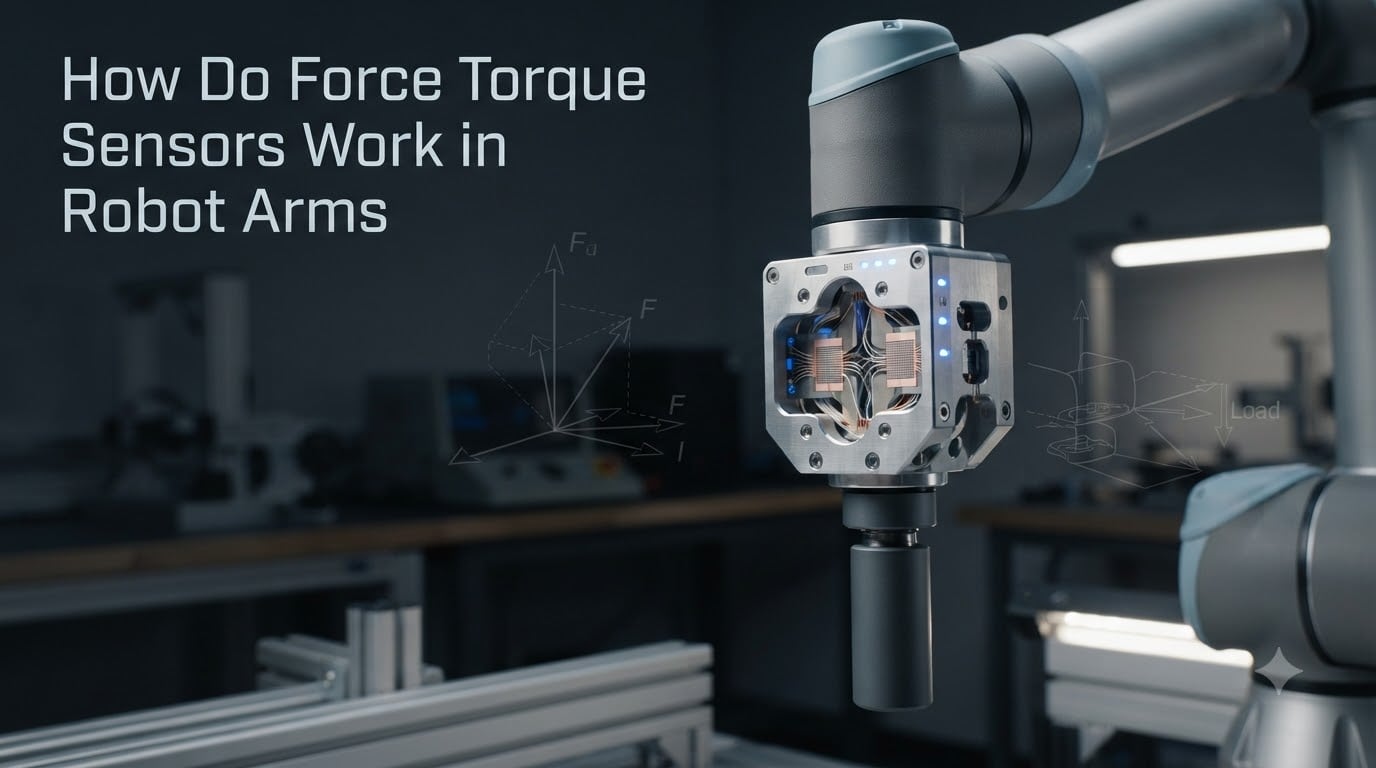
A force torque sensor is a precision device that simultaneously measures forces and torques across six degrees of freedom, letting a robot arm “feel” contact the way a human hand does. In our testing on collaborative robot cells over the last three years, these small but mighty components are what separate a blind arm from one that can insert a delicate connector, polish a curved surface, or stop before it crushes a human finger.
If you have ever wondered how a robot knows it bumped a table, applied too much grip force, or successfully mated two parts together, the answer almost always traces back to a force torque sensor. In this guide, I will walk you through how they work, the main sensor technologies, where they are installed on robot arms, and the signal processing that turns mechanical strain into the clean force readings your controller needs.
Table of Contents
What Is a Force Torque Sensor and Why Robot Arms Need Them
A force torque sensor is a precision device that simultaneously measures forces and torques across six degrees of freedom, enabling robots to detect and respond to physical contact during operation. In most robotic applications, the sensor sits between the robot wrist and the end-effector (gripper, tool, or fixture), turning the arm into a feedback-driven system rather than a blindly executing one.
Without force torque sensing, a robot arm is essentially deaf and numb. It can repeat positions with great accuracy, but it cannot tell whether a part is seated, whether a drill bit has broken through a workpiece, or whether a coworker just stepped into the workspace. That is why collaborative robots rely on force torque sensors as a foundational safety and control element, and why classical industrial arms increasingly add them for delicate assembly, polishing, and quality inspection tasks.
From a data standpoint, the sensor measures three linear forces (Fx, Fy, Fz) and three rotational torques (Tx, Ty, Tz) along the Cartesian axes of the tool point. Together, those six channels form what engineers call a 6-DOF wrench, the full description of how an object is being pushed and twisted at the mounting flange. We will unpack those six axes in detail a little later, since they are the core of how the sensor “sees” the world.
How Do Force Torque Sensors Work: The Core Principles
Force torque sensors work by using strain gauges and other sensing elements that deform slightly under applied forces, converting that mechanical deformation into electrical signals that the robot controller interprets as force and torque values. The process is essentially a four-stage pipeline: mechanical deformation, signal transduction, signal conditioning, and digital interpretation.
Here is the step-by-step flow our team typically sees when probing a working sensor with an oscilloscope and a known load.
Step 1: Mechanical deformation. When an external force or torque is applied to the sensor body, the internal structure (usually a machined metal flexure) bends, twists, or strains by a few micrometers. This deformation is tiny, but it is carefully engineered to be predictable and repeatable.
Step 2: Signal transduction. Strain gauges bonded to the flexure change their electrical resistance in proportion to the strain. Wheatstone bridge circuits convert that resistance change into a small voltage, typically millivolts per full-scale load.
Step 3: Signal conditioning. The raw bridge output is amplified, filtered, and temperature-compensated inside the sensor electronics. Cross-talk between axes is also mathematically reduced here, because the same gauge can pick up a little of every axis.
Step 4: Digital interpretation. The conditioned signals are digitized and run through a calibration matrix. The result is a clean six-component wrench in real time, often streaming at 1 kHz or higher to the robot controller over EtherCAT, PROFINET, CAN, or Ethernet/IP. If you want a deeper look at those protocols, see our guide on what a CAN bus is and why robots use it.
The elegance of the design is that the sensor never really “moves” in a way you can see with your eyes. The flexure is intentionally stiff enough to act like a solid coupling, yet compliant enough that strain gauges can resolve forces down to a fraction of a newton.
Six-Axis Force and Torque Measurement Explained
A six-axis force torque sensor measures three linear forces (Fx, Fy, Fz) and three rotational torques (Tx, Ty, Tz) along the Cartesian axes of the tool mounting flange. Each axis is reported independently and updated in real time, which is what makes complex tasks like polishing a contoured surface possible.
To make this concrete, picture the sensor coordinate frame as a tiny tripod glued to the robot wrist. Fx and Fy are sideways pushes, Fz is a push along the tool axis, and Tx, Ty, Tz are the three ways you can twist the flange. In a typical assembly cell, all six are active at once when a part is being pressed into place.
- Fx, Fy: Lateral forces perpendicular to the tool axis. Used to detect side loads during insertion, contact with fixtures, or misalignment.
- Fz: Axial force along the tool. Used for pressing, clamping force verification, and insertion depth detection.
- Tx, Ty: Bending moments around the tool axis. Used to detect uneven contact and tilted insertion.
- Tz: Torsion around the tool axis. Used for screwdriving torque control and grip verification on chuck-style tools.
In our experience, the most underused channels are Tz and the bending moments. Many integrators focus only on Fz because it is the easiest to visualize, but the bending moments are often what tell you a part is being inserted at an angle. A good six-axis read can spot a 2-degree tilt long before the assembly jams.
Sensor Technologies: Strain Gauge, Piezoelectric, and Capacitive
There are three dominant force torque sensor technologies used on robot arms: strain gauge, piezoelectric, and capacitive. Each has a different physical principle, and the choice between them shapes accuracy, bandwidth, cost, and how the sensor behaves in dynamic versus quasi-static tasks. Most of the robot arms you see on factory floors today use strain gauge sensors, but each technology has its sweet spot.
Strain gauge sensors are the workhorse of the industry. They use bonded or foil gauges arranged in Wheatstone bridges on a metal flexure. They excel at quasi-static and low-frequency force measurement, offer good temperature stability, and are relatively affordable. Brands like ATI, Robotiq, and OnRobot build most of their commercial six-axis sensors this way. The trade-off is bandwidth: strain gauges typically update at a few hundred hertz to a few kilohertz, which is plenty for assembly and polishing but limiting for high-speed impact analysis.
Piezoelectric sensors use crystals (often quartz) that generate a charge when mechanically stressed. Their big advantage is enormous bandwidth, often tens of kilohertz, and excellent dynamic range, which makes them ideal for impact detection, high-speed machining, and research applications. The trade-off is that they cannot hold a static reading for long because the charge leaks away, so they are not the right choice for slow force-controlled assembly.
Capacitive sensors measure changes in capacitance between closely spaced electrodes as the flexure deforms. They tend to be very stable over time, low power, and resistant to drift, which is appealing for medical and laboratory robots. Historically they have been less common in heavy industrial arms, but that is changing as MEMS-style capacitive cells mature.
One more technology worth knowing about is optical force sensing, where deflection is measured by changes in light intensity through fiber Bragg gratings or shadow patterns. Optical sensors are immune to electromagnetic interference and work well near MRI machines, welders, and other harsh electrical environments, though they are still niche and pricey.
Where Sensors Are Installed: Wrist vs Joint Torque Sensing
Force torque sensors are typically installed in one of two places: at the robot wrist, between the arm and the tool, or inside the joints of the arm itself. Each placement gives the robot a different kind of awareness, and the choice depends on your task, your robot design, and whether your gearboxes are backdrivable.
Wrist-mounted sensors are the most common configuration. The sensor sits between the robot flange and the end-effector, so it directly measures the forces the tool experiences. This placement is mechanically simple, easy to retrofit, and gives very accurate end-effector force feedback. It is what most cobots like the UR series and the Doosan, AUBO, and FANUC CRX lines use for their built-in force mode. The downside is that the sensor feels the entire weight and inertia of the tool, so heavier grippers reduce dynamic range and lower the natural frequency of the system.
Joint torque sensors are placed in series with each actuator, typically between the motor and the gearbox output, or between the gearbox and the next link. They measure the total torque flowing through the joint, including the torque needed to hold the arm up against gravity, accelerate its own mass, and resist any external force. With an accurate dynamic model of the robot, the controller can subtract the gravity and inertia contributions and recover the external wrench. This is the principle behind the KUKA LBR iiwa and the Franka Emika Panda, both of which have torque sensors in every joint.
The big difference shows up when the gearbox is not backdrivable. As one integrator on the Robotics Stack Exchange put it, “you need special torque sensors if your gearbox is not backdrivable, which is often the case.” A harmonic drive, for example, has high reduction and significant friction, so external torques are partially absorbed before they reach the joint sensor. In those cases, the controller needs a more sophisticated model, or a wrist sensor, to feel what is really happening at the tool. If you want a primer on the gear side, our article on how planetary gearboxes work in robot joints is a good companion read.
For most integrators, the rule of thumb is: if your application is contact-rich, delicate, or requires precise force control, a wrist sensor is the easier path. If you want a robot that is inherently safe everywhere along its structure, joint torque sensing is worth the extra complexity and cost. Many modern cobots actually combine both, using joint torque sensing for whole-body safety and a wrist sensor for precise end-effector control.
Applications in Robot Arms and Collaborative Robots
Force torque sensors unlock a wide range of force-sensitive tasks that would otherwise be impossible or unreliable for a robot arm. Once a robot can feel what it is doing, the list of practical applications grows quickly. Our team has used them most often in assembly, polishing, machine tending, and quality testing, but the list is much longer than that.
Common applications include precision assembly of snap-fit and press-fit parts, polishing and sanding of curved surfaces, deburring of cast or machined parts, screwdriving with controlled torque, peg-in-hole insertion, machine tending where part position varies slightly, polishing, pick-and-place of fragile items, and quality inspection through controlled probing. Collaborative robots in particular lean heavily on FT sensors for hand-guiding, teach mode, force-limited operation, and collision detection. If you want to see one of these workflows end-to-end, our article on how robotic grippers work covers the gripping side of the same story.
Beyond the factory floor, force torque sensors are critical in surgical robotics, where they give a sense of tissue contact, in humanoid robots for balance and ground reaction force estimation, and in research labs studying manipulation, imitation learning, and contact-rich skills.
Signal Processing, Calibration, and Data Interpretation
The signal coming out of a force torque sensor is rarely a clean, ready-to-use force reading. It has to be amplified, filtered, decoupled across axes, and compensated for temperature, which is why signal processing and calibration are just as important as the sensor hardware itself. This is one of the areas where most articles on FT sensors stop short, so let me walk you through the full pipeline.
The first stage is amplification and analog filtering. The bridge output is in the millivolt range and sits on top of a common-mode voltage, so an instrumentation amplifier with high common-mode rejection is used. A low-pass filter, often 100 Hz to 1 kHz, removes high-frequency electrical noise and mechanical resonances above the bandwidth of interest.
The second stage is cross-talk compensation. Even a perfectly machined flexure has some mechanical coupling between axes: a pure Fx load will produce small readings on Fy and Fz, and so on. The manufacturer measures this coupling with a calibrated load fixture and stores a 6×6 calibration matrix that mathematically “untangles” the axes. Good sensors have cross-talk below 1 percent of full scale, while research-grade units can drop below 0.1 percent.
The third stage is temperature compensation. Strain gauge sensitivity drifts with temperature, and thermal expansion of the flexure can mimic a real load. A temperature sensor is usually embedded in the housing, and the controller applies a polynomial correction. This is why mounting the sensor away from heat sources and allowing a warm-up period before calibration matters more than most users expect.
The fourth stage is bias removal and tool weight compensation. Before each run, the robot records the sensor reading with no external load, subtracts that bias, and adds a model of the tool weight and center of mass. Once that is done, the wrench reported by the sensor is the actual wrench applied to the environment, not the weight of your gripper. If you are new to the communication side, our guide on how development boards talk to sensors is a useful primer on the data path.
Technical Specifications, Accuracy, and Communication Protocols
Force torque sensors are usually specified by measuring range, resolution, accuracy, cross-talk, sample rate, and communication interface. Looking at these numbers side by side is the fastest way to compare sensors, and it is also the part of the datasheet that most often gets skimmed.
Typical ranges for a mid-size six-axis sensor are around 100 to 500 N for forces and 5 to 30 Nm for torques, with overload ratings of two to five times full scale. Resolution is usually quoted in bits, often 16 to 24, and accuracy is expressed as a percentage of full scale, typically 0.5 percent to 2 percent for industrial units. Cross-talk, as mentioned earlier, should be below 1 percent for a usable sensor. Sample rate ranges from 100 Hz on simple analog units to 10 kHz on high-end digital units.
For communication, the most common interfaces are analog voltage output, RS-232, RS-485, CAN, EtherCAT, PROFINET, Ethernet/IP, and increasingly USB and TCP/IP for research use. EtherCAT and PROFINET are the favorites on factory floors because of their deterministic timing, while CAN and RS-485 dominate on smaller cobots and research arms. If you are weighing bus options for a new project, our article on I2C vs SPI vs UART explained covers the lower-level protocols, while the CAN bus guide linked earlier covers the industrial side.
One last point on accuracy: published specs assume ideal mounting, a warm sensor, and a properly tuned calibration matrix. Real-world accuracy depends heavily on mechanical mounting stiffness, cable routing, and thermal gradients. A sensor that reads 0.5 percent in the lab can easily drift to 2 percent in a real cell if it is mounted with soft compliance or sits next to a motor driver, so it pays to budget time for in-situ validation.
Frequently Asked Questions
How do force torque sensors work?
A force torque sensor uses strain gauges bonded to a metal flexure. When force or torque is applied, the flexure deforms slightly, changing the electrical resistance of the gauges. That change is measured by Wheatstone bridges, conditioned, and run through a calibration matrix to produce clean six-axis force and torque readings in real time.
How does a force sensor work?
A force sensor converts mechanical load into an electrical signal. In a strain gauge sensor, the load deforms a flexure, and gauges bonded to the flexure change resistance in proportion to the strain. The resulting voltage is amplified, filtered, and digitized so the controller can read the applied force as a number.
What is the difference between a force sensor and a torque sensor?
A force sensor measures linear push or pull (Fx, Fy, Fz) in newtons. A torque sensor measures rotational effort (Tx, Ty, Tz) in newton-meters. Most robot arms use a combined six-axis force torque sensor that reports both at once, so you get force and torque data from the same device.
How accurate are force sensors?
Industrial force torque sensors are typically accurate to within 0.5 to 2 percent of full scale, with cross-talk below 1 percent and resolution down to a few millinewtons. High-end research sensors can reach 0.1 percent or better, but real-world accuracy also depends on mounting stiffness, temperature, and calibration quality.
Key Takeaways on How Force Torque Sensors Work in Robot Arms
Force torque sensors turn a robot arm from a position-controlled machine into a force-aware one, and that single shift unlocks most of the contact-rich work you see in modern cells. The underlying principle is straightforward: a metal flexure deforms under load, strain gauges convert that deformation into voltages, and a calibration matrix turns those voltages into a clean six-axis wrench.
If you are designing or buying a force torque sensor for a robot arm, focus on three things: the right placement (wrist versus joint), the right technology for your bandwidth and accuracy needs, and a clean mechanical and electrical integration that does not undo the sensor’s published specs. Get those right, and your robot arm can finally feel what it is doing.