
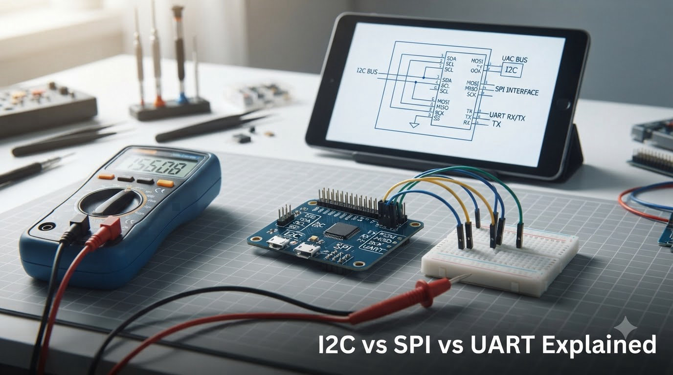
If you have ever wired a sensor to an Arduino, flashed firmware to an ESP32, or watched a robot’s IMU stream data to its main controller, you have used I2C, SPI, or UART. These three protocols carry nearly every byte of data inside embedded systems, and choosing the wrong one can leave you debugging ghost signals at 2 AM instead of finishing your robot.
I have spent the last decade building robots for industrial inspection, drone swarms, and hobby projects. In that time, I have wired hundreds of sensors using I2C, SPI, and UART. This guide is the comparison I wish I had on day one. By the end, you will know exactly how each protocol works, when to pick it, and how to avoid the most common pitfalls in robotics projects.
This is a complete 2026 walkthrough of I2C vs SPI vs UART. We will cover architecture, wiring, speed, and real-world robotics use cases. If you are new to embedded systems, start with the communication protocols like I2C, SPI, and UART in our robot power guide to understand how data and power coexist on a robot.
Table of Contents
I2C vs SPI vs UART at a Glance
The three protocols solve the same problem (moving bytes between chips) in three different ways. Here is the short version before we dig in.
I2C uses two wires and supports many devices through 7-bit or 10-bit addressing. SPI uses four wires and supports one device per chip select line, but runs much faster and is full-duplex. UART uses two wires for simple, point-to-point asynchronous communication without a shared clock.
Think of I2C as a phone line where everyone shares the same wire but calls different extensions. SPI is like a private conference line per device. UART is a direct walkie-talkie between two devices.
Quick Comparison Table
| Feature | I2C | SPI | UART |
|---|---|---|---|
| Wires needed | 2 (SDA, SCL) | 4+ (MOSI, MISO, SCK, CS) | 2 (TX, RX) |
| Clock type | Synchronous | Synchronous | Asynchronous |
| Speed | 100 kHz to 5 MHz | 1 MHz to 100+ MHz | Up to 1 Mbaud (typical) |
| Devices on bus | Up to 127 | Limited by CS pins | 1 per UART port |
| Duplex mode | Half-duplex | Full-duplex | Full-duplex |
| Typical range | Under 1 m on a robot | Under 0.5 m | Up to 15 m at low baud |
| Best for | Sensor networks, displays | High-speed sensors, SD cards, displays | Debug, GPS, Bluetooth, peer links |
This table is the cheat sheet. Keep it open while you decide which protocol fits your robot.
What Is I2C and How Does It Work?
I2C (Inter-Integrated Circuit) is a two-wire, addressable serial bus created by Philips in 1982. It uses one line for data (SDA) and one for the clock (SCL). Every device on the bus has a unique address, so the master can talk to up to 127 peripherals using only two pins.
I2C is synchronous, meaning the master drives the clock and the slaves follow it. Data is grouped into 8-bit bytes with an acknowledge bit after each byte. The bus is open-drain, which means devices can only pull the line low. That is why pull-up resistors are required on both lines.
I2C supports multiple masters with hardware arbitration. If two masters try to talk at the same time, the one driving the line low first wins. This makes I2C a great fit for sensor networks where you want to add or remove devices without rewiring the robot.
I2C Wiring and Pull-Up Resistors
I2C wiring is the simplest of the three. You connect SDA to SDA, SCL to SCL, and add two pull-up resistors to your logic voltage (usually 3.3 V or 5 V). The pull-up value depends on bus speed and capacitance. For most robot sensor buses at 400 kHz, 4.7 kΩ resistors work well.
If you forget the pull-ups, the bus stays stuck low and nothing works. I learned this the hard way on a hexapod where three IMU boards shared the same I2C bus with no pull-ups. After adding two resistors, every sensor came online instantly.
Adafruit’s STEMMA QT and SparkFun’s Qwiic systems standardise 3.3 V I2C with JST-SH cables. They make wiring almost foolproof and include pull-ups on most breakouts.
I2C Speed, Addressing, and Limitations
Standard I2C runs at 100 kHz. Fast-mode I2C runs at 400 kHz. Fast-mode Plus hits 1 MHz, and some modern controllers support up to 5 MHz. In practice, on a robot PCB with multiple devices, 400 kHz is the sweet spot.
Every I2C device has a 7-bit or 10-bit address. Many cheap sensors (MPU6050, BME280, and most OLED displays) use the same default 0x68 or 0x76 address. When two devices share an address, you get a bus collision.
To fix address collisions, you can change the address on supported chips using a jumper or solder bridge. If that is not possible, you put each device on a separate I2C bus, or you use an I2C multiplexer like the TCA9548A.
When to Use I2C in Robotics
I2C shines on robots with many low-bandwidth sensors. You will see I2C used for IMUs, magnetometers, temperature sensors, OLED displays, and GPIO expanders. It is also used to talk to motor drivers that accept I2C commands.
Common robotics I2C devices include the MPU6050 IMU, BME280 environmental sensor, SSD1306 OLED display, PCA9685 servo driver, and DRV2605 haptic driver. Our robot power article explains why these low-power devices pair well with I2C on a dedicated logic rail.
What Is SPI and How Does It Work?
SPI (Serial Peripheral Interface) is a four-wire, full-duplex protocol developed by Motorola in the 1980s. It uses separate lines for data in (MISO), data out (MOSI), clock (SCK), and one chip select (CS) line per device.
SPI is synchronous and master-driven. The master controls the clock and pulls the chip select line low to talk to a specific device. Because every device needs its own CS line, the number of usable devices on a bus depends on how many GPIO pins your microcontroller can spare.
SPI is faster than I2C because it has no addressing overhead and can shift data in both directions at the same time. It is the protocol of choice for SD cards, TFT displays, high-speed ADCs, and radio modules.
SPI Wiring and Chip Select
SPI wiring is straightforward but uses more pins than I2C. A typical setup needs four wires per bus, plus one extra CS wire per device. On a small robot, this can eat up GPIO quickly.
You can daisy-chain CS lines with shift registers to drive more devices, but this is rare on hobby robots. Most projects just use one CS pin per device and accept the GPIO cost.
Watch out for SPI voltage mismatch. Many modern sensors run at 3.3 V, but some Arduino boards use 5 V logic. Always check the datasheet or use a level shifter to avoid frying your sensor.
SPI Speed, Modes, and Trade-offs
SPI speed depends on your microcontroller. Arduino Uno runs SPI up to about 8 MHz. ESP32 and Raspberry Pi Pico can push SPI to 80 MHz or higher. SD card readers and TFT displays benefit enormously from this extra bandwidth.
SPI uses four clock polarity and phase modes (Mode 0 through Mode 3). The master and slave must agree on the same mode. Mode 0 (CPOL=0, CPHA=0) is the most common, but you should always check the device datasheet.
The biggest downside of SPI is the wiring cost. Every additional device needs another CS pin, which is why many hobbyists prefer I2C when they need many low-speed devices.
When to Use SPI in Robotics
SPI is the right call when speed matters. You will see SPI used for SD card logging on data-acquisition robots, TFT displays for fast screen updates, high-speed IMUs like the ICM-42688, and external ADCs for precision sensing.
SPI is also common on radio modules (nRF24L01, LoRa SX1278) and flash memory chips. If your robot needs to log camera frames, drive a fast display, or stream raw sensor data at high rates, SPI is your friend.
What Is UART and How Does It Work?
UART (Universal Asynchronous Receiver-Transmitter) is the simplest of the three protocols. It uses two wires, transmit (TX) and receive (RX), and has no shared clock. The two devices must agree ahead of time on a baud rate, data bits, parity, and stop bits.
UART is asynchronous. Each frame starts with a start bit, carries 5 to 9 data bits, optionally a parity bit, and ends with one or two stop bits. Because there is no clock line, both sides must sample the incoming bits at the same agreed rate.
UART is full-duplex on the hardware level. Each side has its own TX and RX, so they can transmit and receive at the same time. Most microcontrollers have at least one hardware UART, and software UART libraries let you add more on spare GPIOs.
UART Baud Rate and Distance
UART baud rate is the symbol rate. Common values are 9600, 115200, 921600, and 1 Mbaud. The faster you go, the more sensitive the link becomes to noise and timing drift.
At 115200 baud, a typical UART link can run reliably over several metres of cable. The classical limit is about 15 metres at low baud rates, but on a robot you usually keep UART runs under a metre to avoid noise from motors and switching regulators.
RS-232 and RS-485 are electrical standards built on top of UART. RS-232 uses high-voltage signalling for legacy computer ports. RS-485 uses differential signalling for industrial networks up to 1200 metres.
When to Use UART in Robotics
UART is the king of debug consoles and peer-to-peer links. Almost every microcontroller boots with a UART for serial monitor output. It is also the default protocol for GPS modules, Bluetooth HC-05/HC-06 boards, ESP8266 and ESP32 AT commands, and many radio modems.
UART is great when you need to talk to one specific device and don’t want to share a bus. Many robots use UART for the main controller-to-secondary-controller link, like a Raspberry Pi talking to an Arduino Mega for real-time motor control.
How to Choose Between I2C, SPI, and UART
Now that you know how each protocol works, here is how to pick the right one for your robot. The decision usually comes down to four questions: how fast, how many devices, how much wiring, and what kind of traffic.
Decision Criteria at a Glance
Pick I2C when you have multiple low-speed devices, want minimal wiring, and accept a 400 kHz cap. Pick SPI when you need raw speed, can spare the GPIO pins, and have a fixed set of devices. Pick UART when you want a simple debug console, a peer-to-peer link, or you are connecting to a module that speaks UART natively.
Here is a quick decision rule our team uses on every new robot design:
- Many low-speed sensors, two pins only? Use I2C.
- SD card, TFT display, high-speed ADC? Use SPI.
- GPS module, Bluetooth, debug console, peer link? Use UART.
When to Use I2C Instead of SPI
Use I2C when you have several low-bandwidth peripherals and want to keep wiring simple. Sensor hubs, IMU arrays, and OLED displays are classic I2C territory. I2C is also better than SPI when GPIO pins are scarce, because I2C only needs two shared lines.
I2C is also the right choice when you want to hot-swap devices on a robot. Adding a new sensor only requires connecting two wires and configuring a new address. SPI requires a new CS line and reconfiguration for each added device.
When to Use SPI Instead of I2C
Use SPI when you need throughput above 1 MHz or you need full-duplex traffic. SD card logging, TFT screen refresh, and high-speed IMU streams all benefit from SPI’s extra bandwidth. If timing matters more than wiring, SPI wins.
SPI is also better than I2C in electrically noisy environments because its push-pull drivers create stronger edges than I2C’s open-drain pull-ups. On robots with big motors, SPI links are often more reliable over the same distance.
When to Use UART Instead of Both
Use UART when you want a simple, debuggable link between two devices or to talk to a module that expects UART. UART is also the right call for long cable runs at low speed, like a tether or a remote sensor pod on a long cable.
UART is unbeatable for one-off debug prints and module configuration. Almost every robotics project boots with a UART serial monitor, even if I2C and SPI handle the rest of the data.
Can You Mix I2C, SPI, and UART on One Robot?
Yes, and you should. Most real robots use all three protocols at the same time. On our team’s quadruped, the main controller runs an IMU and OLED over I2C, drives an SD card and TFT over SPI, and uses UART for the radio link and serial debug.
Mixing protocols lets each subsystem use the best fit. The trick is pin planning. Map out your I2C bus, SPI buses, and UART ports before you order PCBs. Most modern microcontrollers have plenty of peripherals for this.
One tip: pick your I2C bus and SPI bus voltages carefully. Running I2C at 3.3 V and SPI at 5 V on the same board leads to level-shifter headaches. We standardise on 3.3 V logic for every sensor bus and only step up to 5 V when we have to drive a specific actuator.
Robotics Use Cases: Which Protocol Goes Where
Let’s ground the I2C vs SPI vs UART choice in real robot subsystems. These are the patterns we use on actual machines.
Mobile Robots and Humanoids
Mobile robots and humanoids use I2C for IMUs, magnetometers, and OLED status displays. They use SPI for TFT screens, SD card loggers, and high-speed cameras. They use UART for the main controller link to a Raspberry Pi or Jetson companion computer.
On a humanoid, the joint encoders often go over SPI for high refresh rates, while battery management runs on I2C for cell voltage and temperature telemetry. The serial debug port is UART, period.
Drones and Quadcopters
Drones push the limits of SPI because every millisecond counts. Flight controllers use SPI for gyroscopes, accelerometers, and radio receiver modules. I2C is reserved for compass modules and barometers where bandwidth is low. UART handles GPS receivers and the radio link to the pilot’s transmitter.
On a racing drone, every gram and every microsecond matters. SPI is the only protocol that keeps up with the 8 kHz control loop, so almost every sensor on a flight controller is SPI.
Robotic Arms and Manipulators
Robotic arms lean heavily on I2C for servo driver boards like the PCA9685. Each driver board addresses up to 16 servos over I2C, which keeps wiring manageable. SPI is used for force-torque sensors and high-precision absolute encoders. UART handles teach-pendant communication and safety estop chains.
For collaborative robots, RS-485 over UART is common for motor controllers because the differential signalling rejects the motor noise that would otherwise corrupt an I2C or SPI bus.
Troubleshooting Common I2C, SPI, and UART Problems
Even experienced engineers spend hours debugging communication issues. Here are the three failures I see most often on robotics projects and how to fix them.
I2C Addressing Conflicts and Stuck Buses
The most common I2C problem is two devices sharing the same address. The symptoms are random NACK errors, missing devices in an I2C scanner, or the entire bus hanging low. Run an I2C scanner sketch and check which addresses appear. If two devices respond at the same address, you need to change one or use a multiplexer.
If the bus hangs low, check your pull-up resistors. Pull them and the SDA/SCL lines should bounce back to high when no device is talking. If they stay low, you have a short or a stuck device.
SPI Wiring Mistakes and Mode Mismatches
SPI issues usually come from wrong chip select wiring or clock mode mismatches. If a SPI device responds with garbage data, try the other SPI modes (0 through 3). Also confirm the CS pin is wired to the correct GPIO and is being driven low during transactions.
On long SPI traces, signal integrity becomes an issue. Keep SPI cables short, use ground between data lines, and add series resistors if you see ringing on the clock edge.
UART Baud Rate and Voltage Mismatches
UART problems are almost always baud rate, voltage, or TX/RX crossover mistakes. Both sides must use the same baud rate, data bits, parity, and stop bits. TX on one side must go to RX on the other, not TX to TX.
If you see garbage characters in your serial monitor, you have a baud rate mismatch. If you see nothing at all, check that TX/RX are crossed and that logic levels match. A logic analyser or cheap USB-to-UART adapter is the fastest way to diagnose UART issues.
Frequently Asked Questions About I2C, SPI, and UART
What is the difference between UART and I2C?
UART is an asynchronous protocol that uses two wires for direct point-to-point communication between two devices at an agreed baud rate. I2C is a synchronous protocol that uses two wires for a shared multi-drop bus where devices are addressed by a 7-bit or 10-bit address. UART is best for simple peer links and debug consoles, while I2C is best for connecting multiple low-speed sensors with minimal wiring.
Is I2C faster than SPI?
No. SPI is faster than I2C in most real-world robotics designs. Standard I2C runs at 100 kHz to 400 kHz, with fast-mode Plus reaching 1 MHz. SPI commonly runs at 8 MHz on Arduino boards and up to 80 MHz on ESP32 or Raspberry Pi Pico. SPI also shifts data in both directions at the same time, so its effective throughput is much higher than I2C.
When should I use SPI instead of I2C?
Use SPI when you need throughput above 1 MHz, full-duplex communication, or rock-solid signal edges in electrically noisy environments. SPI is the right choice for SD card logging, TFT displays, high-speed IMUs, external ADCs, and radio modules. The trade-off is more wiring: each SPI device needs its own chip select line in addition to the shared MOSI, MISO, and SCK lines.
When should I use I2C instead of SPI?
Use I2C when you have several low-bandwidth sensors, want to save GPIO pins, and accept a 400 kHz cap on the bus. I2C is ideal for IMU arrays, OLED displays, GPIO expanders, and small motor driver boards. It also lets you add and remove devices without redesigning the wiring harness, because every device shares the same two lines and uses a unique address.
Can I use I2C, SPI, and UART on the same microcontroller?
Yes, and most real robots do. Modern microcontrollers like the ESP32, STM32, and Raspberry Pi Pico expose multiple I2C, SPI, and UART peripherals. You can run an I2C sensor bus, an SPI display, and a UART debug console simultaneously. Just plan your pin map carefully so that each peripheral has the right dedicated pins and make sure logic voltage levels match across all devices.
Do I2C devices need pull-up resistors?
Yes. I2C uses open-drain drivers, so both the SDA and SCL lines need external pull-up resistors to your logic voltage. For 400 kHz buses, 4.7 kΩ resistors are a safe default. Many breakout boards include pull-ups on board, but if you connect multiple boards you may end up with too-strong pull-ups, which can prevent the bus from working. In that case, desolder or remove pull-ups from some boards.
Final Thoughts on I2C vs SPI vs UART
Choosing between I2C vs SPI vs UART comes down to wiring, speed, and how many devices you need on the bus. I2C keeps your wiring tidy when you have many low-bandwidth sensors. SPI delivers raw throughput for displays, SD cards, and high-speed IMUs. UART is unbeatable for debug consoles, GPS modules, and direct peer links.
Most robots end up using all three. Plan your pin map before you order PCBs, keep your I2C bus under one metre, add pull-ups on SDA and SCL, and don’t forget to cross TX and RX on UART links. Get those four things right and your I2C vs SPI vs UART debugging time will drop dramatically.
If you want to go deeper on the robotics side, read our guide on why robots use separate power for logic and motors. It shows exactly how to keep your communication buses clean while driving noisy actuators. Now grab your soldering iron and wire up your next robot with confidence.