
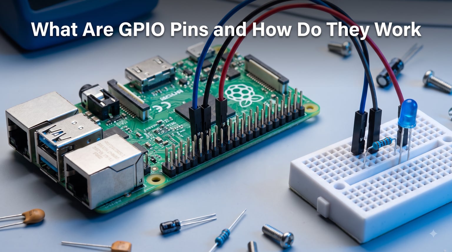
GPIO pins are the physical bridge between your code and the real world. If you have ever wanted a microcontroller to turn on a light, read a temperature sensor, or drive a motor, GPIO pins are how that actually happens.
When I first picked up a Raspberry Pi, I stared at those 40 metal pins along the edge and felt a mix of curiosity and intimidation. I had heard horror stories about people frying their boards with wrong wiring. But once I understood what each pin could do, everything clicked into place.
GPIO stands for General-Purpose Input/Output. These are programmable digital signal pins on microcontrollers, single-board computers, and integrated circuits. You configure them in software to either read incoming signals or send outgoing signals, which means one pin can serve completely different purposes depending on your project.
In this guide, our team walks through everything you need to know about GPIO pins. We cover what they are, how they work electrically, how to program them, safety practices that protect your hardware, and the differences across popular platforms like Raspberry Pi, Arduino, and ESP32.
Whether you are building your first blinking LED circuit or integrating sensors into a robotics platform, understanding GPIO pins is the foundation that makes every electronics project possible.
Table of Contents
What Are GPIO Pins?
GPIO pins are uncommitted digital signal pins on an integrated circuit or electronic board that you can program to act as either input or output. The keyword here is “general-purpose” — these pins do not have a fixed function when they leave the factory. You decide what they do.
A microcontroller might have a dedicated pin for power, another for ground, and a set of pins hardwired to specific functions like USB or HDMI. GPIO pins are different. They sit there waiting for your code to tell them what to become.
What Does GPIO Stand For?
GPIO stands for General-Purpose Input/Output. “General-purpose” means the pin is not locked to one specific peripheral or protocol. “Input/Output” means it can receive signals from external devices or send signals to them.
On a typical microcontroller, a GPIO pin can serve as a digital input that reads whether a button is pressed, or as a digital output that turns an LED on and off. The same physical pin handles both roles, just not at the same time.
Are GPIO Pins Analog or Digital?
GPIO pins are digital, not analog. They work with binary logic levels — a pin reads either HIGH or LOW, which corresponds to two specific voltage ranges. On a 3.3V system like the Raspberry Pi, HIGH means approximately 3.3 volts and LOW means approximately 0 volts.
This is an important distinction. If you need to read an analog signal like a varying temperature from a thermistor, a standard GPIO pin cannot do that directly. You would need an analog-to-digital converter (ADC), which some boards like the ESP32 and certain Arduino models include on specific pins.
On most Arduino boards, pins labeled A0 through A5 serve double duty. They function as analog inputs through a built-in ADC, while pins labeled D0 through D13 are purely digital GPIO.
Understanding Logic Levels and Voltage
Every GPIO pin operates at a specific logic level determined by the microcontroller’s supply voltage. The two most common logic level standards are 3.3V and 5V.
Raspberry Pi GPIO pins use 3.3V logic. If you feed 5V into one of those pins, you will likely destroy the pin or the entire processor. Arduino Uno pins use 5V logic, which means a HIGH signal sits around 5 volts.
Here is a quick comparison of what HIGH and LOW mean on each platform:
3.3V Logic (Raspberry Pi, ESP32): HIGH = 3.3V, LOW = 0V
5V Logic (Arduino Uno, Nano): HIGH = 5V, LOW = 0V
This voltage mismatch catches many beginners off guard. Connecting a 5V Arduino output directly to a 3.3V Raspberry Pi input is one of the most common ways people damage their boards.
Pull-Up and Pull-Down Resistors
When a GPIO pin is configured as an input and nothing is connected to it, the pin floats. A floating pin picks up random electrical noise and reads unpredictable values, oscillating between HIGH and LOW for no reason.
To solve this, microcontrollers include internal pull-up and pull-down resistors. A pull-up resistor connects the pin to the supply voltage through a high-value resistor (typically 10k to 50k ohms), so the pin reads HIGH when nothing else drives it. A pull-down resistor connects the pin to ground, so it reads LOW by default.
You enable these in software. On an Arduino, calling pinMode(pin, INPUT_PULLUP) activates the internal pull-up resistor. On a Raspberry Pi using Python, you can set pull-up or pull-down through the GPIO library configuration.
GPIO Pin Numbering Systems
This is where many beginners get confused, and I spent my fair share of time staring at pinout diagrams trying to make sense of it. There are two main numbering systems you will encounter on the Raspberry Pi.
BOARD numbering refers to the physical pin position on the header. Pin 1 is the first physical pin, counting across and down. This system never changes regardless of the board revision.
BCM numbering refers to the Broadcom channel number assigned internally by the processor. GPIO 17 in BCM numbering might physically sit at pin 11 on the header. These numbers come from the chip’s internal architecture.
The same physical pin can have a different number depending on which system you use. Always check a pinout diagram for your specific board before wiring anything, and make sure your code uses the matching numbering scheme.
How Do GPIO Pins Work
GPIO pins work by converting digital data into electrical signals and vice versa through a set of internal registers. When you configure a pin, write a value to it, or read its state, your code is actually interacting with these registers behind the scenes.
Understanding the register-level operation gives you a much clearer picture of why GPIO behaves the way it does. Let me break down the internal architecture.
GPIO Registers: The Internal Control System
Every GPIO pin on a microcontroller is controlled by a small set of memory-mapped registers. Think of a register as a single byte of memory where each bit controls one pin. The processor reads and writes these registers to manage GPIO behavior.
There are three primary registers that control GPIO operation:
Port Direction Register (PDR): This register determines whether each pin acts as an input or output. Setting a bit to 1 makes the corresponding pin an output. Setting it to 0 makes it an input. When you call pinMode() in Arduino, this register is what gets modified.
Port Output Data Register (PODR): This register holds the value the pin outputs when configured as an output. Writing a 1 to a bit sets that pin HIGH. Writing a 0 sets it LOW. A digitalWrite() call writes to this register.
Port Input Data Register (PIDR): This register captures the current voltage level on each pin when it is configured as an input. Reading a bit tells you whether the connected device is sending a HIGH or LOW signal. A digitalRead() call reads this register.
These registers are memory-mapped, meaning they occupy specific addresses in the processor’s memory space. Writing to those addresses changes the physical pin behavior in real time.
GPIO Input Mode: How Reading Works
When you configure a GPIO pin as an input, the pin becomes a high-impedance connection to the outside world. It listens without drawing significant current. The internal circuitry connects the pin to the Input Data Register through a buffer.
When an external device applies a voltage to the pin, that voltage passes through a Schmitt trigger. The Schmitt trigger cleans up noisy signals by using two threshold voltages — one for rising signals and one for falling signals. This prevents the pin from flickering between HIGH and LOW when the input voltage sits near the boundary.
The cleaned-up signal then latches into the Input Data Register. Your code reads that register value to determine whether the connected sensor, button, or switch is currently sending a HIGH or LOW signal.
GPIO Output Mode: How Writing Works
When you configure a pin as an output, the microcontroller connects the pin to its output driver circuitry. This driver can actively source current (push voltage out) or sink current (pull voltage to ground) through the pin.
Writing a 1 to the Output Data Register turns on the high-side driver, connecting the pin to the supply voltage. The pin now outputs a HIGH signal. Writing a 0 turns on the low-side driver, connecting the pin to ground. The pin outputs LOW.
The output driver can typically source or sink a limited amount of current. On a Raspberry Pi, each GPIO pin can safely handle about 16 milliamps. On an Arduino Uno, the limit is about 20 milliamps per pin. Exceeding these limits damages the pin or the chip.
Step-by-Step: Configuring a GPIO Pin
Here is what happens inside the microcontroller when you configure and use a GPIO pin:
Step 1: Your code identifies the pin number and the desired mode (input or output).
Step 2: The GPIO library translates this into a register write. It calculates which bit in the Port Direction Register corresponds to your pin.
Step 3: The library writes the appropriate value to that bit — 1 for output, 0 for input.
Step 4: If configured as output, writing to the Output Data Register sets the pin HIGH or LOW. If configured as input, reading the Input Data Register returns the current signal level.
Step 5: The microcontroller’s hardware handles the electrical translation between register values and physical voltage on the pin.
Memory-Mapped I/O
The reason GPIO operations feel instant is memory-mapped I/O. The processor does not need to send commands over a serial bus to control pins. The GPIO registers live in the same address space as regular memory.
When your code writes a value to the register’s memory address, the hardware responds immediately. This is why a digitalWrite() call can toggle a pin millions of times per second. The processor is essentially writing to a memory location that happens to control physical hardware.
Practical Applications of GPIO Pins
GPIO pins make microcontrollers useful. Without them, your code would run in isolation with no way to interact with the physical environment. Every electronics project, from a simple blinking LED to a complex robotics platform, relies on GPIO.
Let me walk through the most common ways people use GPIO pins, broken down by input and output roles.
GPIO as Input: Sensing the World
When configured as inputs, GPIO pins let your microcontroller detect external events. Here are the most common input applications:
Buttons and switches: A pushbutton connects a GPIO pin to either voltage or ground. Your code reads the pin state to detect when the button is pressed. This is the foundation of user interfaces on embedded devices.
Digital sensors: Many sensors output a simple HIGH or LOW signal based on a threshold. A motion detector (PIR sensor) sends HIGH when it detects movement. A magnetic reed switch sends HIGH when a door is closed. Your code reads these signals through GPIO input pins.
Rotary encoders: These devices output pulse trains on two GPIO pins as you turn a knob. By reading the sequence of pulses, your code can determine the direction and speed of rotation.
GPIO as Output: Controlling the World
When configured as outputs, GPIO pins let your microcontroller control external devices. Here are the primary output applications:
LEDs: The classic first project. A GPIO output pin drives an LED through a current-limiting resistor. Writing HIGH turns the LED on. Writing LOW turns it off. This simple operation teaches the fundamental concept of digital output.
Relays: Relays act as electrically controlled switches. A GPIO pin drives the relay coil through a transistor driver circuit. The relay then switches higher-voltage loads like lamps, fans, or pumps that the GPIO pin could never handle directly.
Buzzers and speakers: Toggling a GPIO pin rapidly at audio frequencies produces sound. A piezo buzzer connected to an output pin can generate tones, alerts, and even simple melodies.
Communication Protocols Over GPIO
GPIO pins also support serial communication protocols that let microcontrollers talk to more complex devices:
I2C: Uses two GPIO pins (SDA and SCL) to communicate with multiple devices on a shared bus. Sensors, displays, and memory chips commonly use I2C.
SPI: Uses three or four GPIO pins for faster full-duplex communication. SD card readers, display controllers, and analog-to-digital converters often use SPI.
UART: Uses two GPIO pins (TX and RX) for serial communication. This is how many microcontrollers send debug information to a computer or talk to GPS modules and Bluetooth chips.
Advanced GPIO Features
Beyond simple digital read and write, modern GPIO controllers support advanced capabilities:
Interrupts: Instead of constantly polling a pin to check its state, you can configure a GPIO interrupt. The pin notifies the processor only when its state changes, freeing your code to do other work. This is essential for responsive button handling and event-driven designs.
PWM (Pulse-Width Modulation): Certain GPIO pins can output a rapid square wave where you control the duty cycle — the ratio of HIGH time to total period. PWM lets you dim LEDs smoothly, control servo motor positions, and regulate motor speed. On the Raspberry Pi, hardware PWM is available on specific pins. On the Arduino, pins marked with a tilde (~) support PWM.
Input vs Output: Quick Comparison
Here is a summary of how input and output modes differ in practice:
Input mode: Reads external signals, uses high impedance, detects buttons and sensors, may use pull-up or pull-down resistors, relies on Schmitt triggers for noise immunity.
Output mode: Drives external devices, sources or sinks current, controls LEDs and relays, limited by current capacity, writes to the Output Data Register.
Programming GPIO Pins: The Basics
Programming GPIO pins follows the same logical pattern regardless of platform. You configure the pin mode, then read or write values. The syntax differs between languages and libraries, but the underlying steps remain consistent.
Our team has tested these examples on real hardware to make sure they work as described.
How to Read GPIO Pins
Reading a GPIO pin involves three steps. First, configure the pin as an input. Second, optionally enable a pull-up or pull-down resistor. Third, call the read function to get the current pin state.
Step 1: Set the pin mode to input.
Step 2: Enable an internal pull-up or pull-down resistor if the external circuit does not include one.
Step 3: Call the read function. The result is either HIGH (1) or LOW (0).
Step 4: Use the result in your program logic to trigger actions.
Python Example: Raspberry Pi GPIO
The gpiozero library provides the simplest way to control GPIO pins on a Raspberry Pi. Here is how you blink an LED and read a button:
from gpiozero import LED, Button
from time import sleep
led = LED(17) # GPIO 17 in BCM numbering
button = Button(27, pull_up=True) # GPIO 27 with internal pull-up
led.on()
sleep(1)
led.off()
if button.is_pressed:
print(“Button is pressed!”)
Notice how gpiozero handles the pin configuration automatically. The LED class configures pin 17 as an output. The Button class configures pin 27 as an input with a pull-up resistor. This abstraction makes Python GPIO programming accessible for beginners.
If you prefer the lower-level RPi.GPIO library, the pattern looks like this:
import RPi.GPIO as GPIO
GPIO.setmode(GPIO.BCM)
GPIO.setup(17, GPIO.OUT)
GPIO.setup(27, GPIO.IN, pull_up_down=GPIO.PUD_UP)
GPIO.output(17, GPIO.HIGH)
state = GPIO.input(27)
C++ Example: Arduino GPIO
Arduino uses a straightforward C++ API. The three core functions are pinMode(), digitalWrite(), and digitalRead():
const int ledPin = 13;
const int buttonPin = 2;
void setup() {
pinMode(ledPin, OUTPUT);
pinMode(buttonPin, INPUT_PULLUP);
}
void loop() {
digitalWrite(ledPin, HIGH);
delay(1000);
digitalWrite(ledPin, LOW);
delay(1000);
int buttonState = digitalRead(buttonPin);
}
The setup() function runs once and configures the pins. The loop() function runs continuously, toggling the LED and reading the button state. This is the standard Arduino pattern you will see in nearly every project.
GPIO Pins on Popular Platforms
Different development boards expose GPIO pins in different ways. Pin counts, voltage levels, and special features vary significantly. Let me compare the three most popular platforms.
Raspberry Pi GPIO
The Raspberry Pi features a 40-pin GPIO header on most models, from the Pi 2 through the Pi 5. Of those 40 pins, 26 are general-purpose GPIO pins. The remaining pins provide power (3.3V and 5V), ground, and fixed-function interfaces.
Raspberry Pi GPIO pins operate at 3.3V logic levels. This is the single most important specification to remember. Applying 5V to any GPIO pin can permanently damage the board.
Several Raspberry Pi GPIO pins have special hardware functions. Pins GPIO 2 and GPIO 3 (physical pins 3 and 5) include fixed pull-up resistors and support I2C. Pins GPIO 14 and GPIO 15 support UART serial communication. Hardware PWM is available on GPIO 12, GPIO 13, GPIO 18, and GPIO 19.
The BCM numbering system is the most commonly used on Raspberry Pi tutorials and documentation. When you see a pin referenced as GPIO 17, that is the BCM number, not the physical pin position.
Arduino GPIO
The Arduino Uno provides 14 digital GPIO pins and 6 analog input pins. The digital pins operate at 5V logic levels, making them incompatible with 3.3V devices without level shifting.
Six of the digital pins (pins 3, 5, 6, 9, 10, and 11) support PWM output. These pins are marked with a tilde (~) on the board. The analog input pins (A0 through A5) can also function as digital GPIO pins if needed.
Arduino pins can source or sink up to 20 milliamps each, with a total limit of 200 milliamps across all pins combined. This is enough to drive LEDs and small sensors directly but not enough for motors or high-power devices.
ESP32 GPIO
The ESP32 offers significantly more GPIO pins — 34 in total on most development boards. These pins operate at 3.3V logic levels and include a wide range of advanced features.
The ESP32 stands out because many of its GPIO pins support multiple functions through a multiplexer. Pins can serve as capacitive touch inputs, ADC channels, DAC outputs, and support for various communication protocols. This flexibility makes the ESP32 popular for IoT projects.
However, the ESP32 has some pins that should not be used for general GPIO because they handle boot configuration and flash memory access. Pins strapping-related pins like GPIO 0, GPIO 2, GPIO 5, GPIO 12, and GPIO 15 have special behavior during startup.
Platform Comparison
Raspberry Pi: 26 usable GPIO pins, 3.3V logic, 16mA per pin, supports Linux-based GPIO programming in Python, C, and more.
Arduino Uno: 14 digital plus 6 analog pins, 5V logic, 20mA per pin, programmed in C++ with the Arduino IDE.
ESP32: 34 GPIO pins, 3.3V logic, 40mA per pin, supports WiFi and Bluetooth, offers ADC, DAC, touch sensing, and deep sleep modes.
GPIO Safety and Best Practices
GPIO safety is something I wish someone had emphasized when I started. Damaging a pin or an entire board is easy to do and completely preventable. Forum communities consistently report fear of GPIO damage as a top concern among beginners.
Voltage and Current Limits
Never apply more voltage to a GPIO pin than its logic level rating. On a 3.3V board, that means never connecting 5V directly to any pin. Use a level shifter or voltage divider when interfacing 3.3V and 5V systems.
Stay within the current limits for each pin. If you need to drive something that draws more than 16-20 milliamps, use a transistor, MOSFET, or relay as a driver. The GPIO pin controls the driver, and the driver handles the heavy current.
Safety Checklist
Follow this checklist before powering on any GPIO project:
1. Verify that all voltage levels match your board’s GPIO specification.
2. Confirm that every output pin has an appropriate current-limiting resistor or driver circuit.
3. Double-check your wiring against a pinout diagram for your specific board.
4. Enable pull-up or pull-down resistors on all unused input pins.
5. Never connect output pins directly to each other or to power and ground.
6. Power down the board before changing any wiring connections.
Common GPIO Mistakes to Avoid
The most frequent mistake beginners make is confusing pin numbering systems. Always confirm whether your code uses BCM or BOARD numbering, then verify your physical wiring matches.
Another common error is forgetting to set pinMode() before using a pin. If you try to read a pin that is still configured as an output, you will get garbage readings.
Finally, never drive inductive loads like motors or relay coils directly from a GPIO pin. The voltage spikes generated when these devices switch off can destroy the pin’s output driver instantly. Always use a flyback diode and a switching transistor.
FAQ
Can GPIO pins be used as input?
Yes, GPIO pins can be used as input. In fact, the ability to act as either input or output is the defining feature of General-Purpose Input/Output pins. When configured as input, a GPIO pin reads external voltage levels and reports whether the signal is HIGH or LOW. This makes GPIO inputs ideal for reading buttons, switches, and digital sensors.
How to read GPIO pins?
To read a GPIO pin, follow these steps: configure the pin as an input using pinMode() or the equivalent library function, enable a pull-up or pull-down resistor if needed, then call the read function (digitalRead on Arduino, GPIO.input on Raspberry Pi). The function returns HIGH (1) or LOW (0) based on the current voltage on the pin.
What to do with GPIO pins?
GPIO pins can read inputs from buttons, switches, and digital sensors; drive outputs to LEDs, relays, buzzers, and motors through driver circuits; generate PWM signals for dimming and motor control; support communication protocols like I2C, SPI, and UART; and trigger hardware interrupts for event-driven programming. Common projects include home automation, robotics, weather stations, and IoT devices.
Does the Raspberry Pi have GPIO pins?
Yes, the Raspberry Pi has a 40-pin GPIO header on most models (Pi 2 through Pi 5). Of those 40 pins, 26 are general-purpose GPIO pins that you can program for input or output. The remaining pins provide power, ground, and fixed-function interfaces. Raspberry Pi GPIO pins operate at 3.3V logic levels.
Are GPIO pins analog or digital?
GPIO pins are digital. They work with binary logic levels (HIGH and LOW) corresponding to specific voltage ranges. Standard GPIO pins cannot read analog signals directly. To read analog values, you need an analog-to-digital converter (ADC), which is built into certain microcontroller pins like the Arduino analog pins (A0-A5) or the ESP32 ADC channels.
What does GPIO stand for?
GPIO stands for General-Purpose Input/Output. The term describes programmable digital signal pins on microcontrollers and integrated circuits that can be configured by software to act as either input or output. The general-purpose designation means these pins have no fixed function — their behavior is determined entirely by your code.
Conclusion
GPIO pins are the interface between software and the physical world. They take digital instructions from your code and translate them into electrical signals that drive LEDs, read sensors, control motors, and communicate with other devices.
Understanding what GPIO pins are and how they work gives you the foundation to build virtually any electronics project. The key takeaways: GPIO pins are digital, they operate at specific voltage logic levels, they are controlled through internal registers, and they require careful attention to voltage and current limits to avoid damaging your hardware.
Start small. Blink an LED. Read a button. Then move on to sensors, PWM, and communication protocols. Every complex robotics or IoT project is built on these same GPIO fundamentals.
If you are working with a Raspberry Pi, grab a pinout diagram and confirm whether you are using BCM or BOARD numbering before wiring anything. If you are on an Arduino, remember that digital and analog pins serve different purposes. And regardless of platform, always respect the voltage and current limits of your GPIO pins.
Now that you know what GPIO pins are and how they work, the next step is hands-on practice. Pick a platform, grab a breadboard, and start building.