
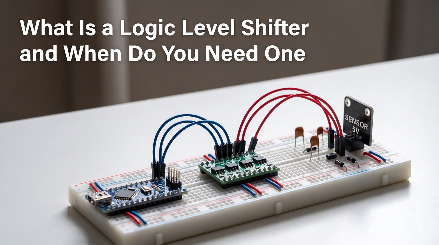
Working on an electronics project and wondering why your 3.3V microcontroller will not talk to a 5V sensor? The answer is almost always voltage incompatibility, and the fix is a small but essential component called a logic level shifter. These tiny circuits solve one of the most common problems in embedded systems and robotics, where mixed-voltage devices need to share data without frying each other.
In this guide, I will break down exactly what a logic level shifter is, how it works, and the specific situations where you absolutely need one. Whether you are connecting an ESP32 to 5V peripherals, driving WS2812B LED strips from a Raspberry Pi, or building a sensor network with mixed voltage domains, this article will help you choose the right approach and avoid the mistakes that lead to dead components.
If you are new to electronic components in robotics, understanding voltage compatibility is one of the first skills you will need. Let us start with the fundamentals.
Table of Contents
What Is a Logic Level Shifter?
A logic level shifter (also called a level translator or logic converter) is an electronic circuit that converts digital signals between different voltage domains. It takes a signal operating at one voltage level, such as 3.3V logic from an ESP32, and safely translates it to another level, like 5V logic expected by an Arduino UNO or a sensor module.
Every digital device defines its own logic HIGH and logic LOW thresholds. A 3.3V microcontroller considers anything above roughly 2.0V as HIGH, while a 5V device might need at least 3.5V to register the same HIGH signal. When those thresholds do not align, communication breaks down or components get damaged.
Level shifters sit between these mismatched devices and handle the voltage translation in both directions. They ensure that each device receives signals within its safe operating range, making them indispensable in any mixed-voltage system.
Why Voltage Levels Matter in Electronics
Digital electronics rely on two voltage states to represent binary data. Logic HIGH (1) is represented by the supply voltage, and logic LOW (0) is represented by ground. The problem is that different logic families and microcontroller generations use different supply voltages.
Older TTL logic and classic Arduino boards run at 5V. Modern microcontrollers like the ESP32, Raspberry Pi Pico, and STM32 series operate at 3.3V. Some sensors and industrial components use 1.8V, while certain LED drivers and motor controllers expect 5V or even 12V signals.
When you send a 5V signal into a 3.3V GPIO pin that is not 5V tolerant, you risk permanent damage to the microcontroller. The overvoltage can blow internal protection diodes, destroy the pin driver circuitry, or gradually degrade the silicon until the chip fails unexpectedly days or weeks later.
The reverse situation is less immediately destructive but equally problematic. A 3.3V output connected to a 5V input might work intermittently because the 3.3V signal sits near the undefined threshold region of the 5V device. You get unreliable communication, corrupted data, and ghosting issues that are maddening to debug.
Forum users on r/AskElectronics and the Arduino forums frequently report this exact scenario. Many say their project “worked fine at first” but became unreliable over time, only to discover that connecting mismatched voltage lines without a level shifter was the root cause all along.
How Logic Level Shifters Work
At a basic level, every logic level shifter does the same job: it translates a signal from one voltage domain to another. But the internal mechanism varies significantly depending on the type of shifter you use.
The simplest approach is a resistive voltage divider. Two resistors in series step down a higher voltage to a lower one based on their ratio. A 5V signal passing through a divider with a 1k ohm and 2k ohm resistor drops to approximately 3.3V. This works for simple unidirectional signals but cannot handle bidirectional communication buses.
MOSFET-based shifters use a transistor as an electronically controlled switch. The classic BSS138 N-channel MOSFET circuit is the backbone of most bidirectional level shifter modules. When the low-voltage side pulls the signal LOW, the MOSFET conducts and pulls the high-voltage side LOW too. When the signal goes HIGH, pull-up resistors on each side restore the voltage to their respective levels.
Dedicated IC solutions like the TXS0108E and TXB0104 use internal transistor networks and one-shot circuits to handle translation automatically. These chips detect signal transitions and actively drive outputs, which means faster switching speeds and better signal integrity than passive circuits.
The key concept to understand is the difference between open-drain and push-pull signaling. Open-drain outputs (used by I2C) rely on external pull-up resistors to define the HIGH state, making them naturally compatible with MOSFET shifters. Push-pull outputs (used by SPI) actively drive both HIGH and LOW states, requiring dedicated ICs or more complex circuits for reliable translation.
When Do You Need a Logic Level Shifter
The short answer is: any time two devices with different operating voltages need to exchange digital signals. Here are the most common scenarios where a logic level shifter is essential.
Connecting a 3.3V microcontroller to 5V sensors or modules. This is the single most common use case. ESP32, ESP8266, Raspberry Pi, and most modern ARM boards run at 3.3V, but many popular sensors, displays, and breakout boards still use 5V logic. Without a level shifter, you risk damaging the microcontroller pin or getting unreliable readings.
Driving WS2812B and other addressable LED strips. These LEDs expect a 5V data signal, but many people drive them from a 3.3V microcontroller like the ESP32. The data signal often works at short distances but degrades rapidly with longer wire runs. A logic level shifter on the data line ensures clean signal transitions and prevents flickering, color glitches, or complete signal loss.
Interfacing with SD card modules. SD cards operate at 3.3V, but many cheap SD card breakout boards include 5V to 3.3V regulators on the power line while leaving the data lines at 5V logic levels. This mismatch causes data corruption and write failures. Engineers on Electronics Stack Exchange frequently recommend adding level shifters when working with SD card modules on 5V microcontrollers.
Communicating between Arduino UNO (5V) and ESP32 (3.3V). If you are building a multi-controller system for robot system integration where an Arduino handles motor control and an ESP32 manages WiFi, the serial communication between them needs level shifting. Sending 5V serial into an ESP32 pin will eventually kill it.
Reading 5V sensors with Raspberry Pi. The Raspberry Pi has strictly 3.3V GPIO pins with no 5V tolerance. Connecting any 5V sensor output directly to a Pi GPIO pin is a guaranteed way to destroy the pin or the entire board. A level shifter is mandatory here.
Working with 12V LED systems or industrial sensors. Some LED controllers and industrial sensors output signals at 12V or 24V. Standard 3.3V or 5V level shifters cannot handle these voltages directly. You need specialized high-voltage shifters or optocoupler-based isolation circuits.
Types of Logic Level Shifters
There are four main types of level shifters, each with different trade-offs in cost, speed, complexity, and capability. Choosing the right one depends on your specific application.
1. Resistor Voltage Divider
The simplest and cheapest method uses two resistors to step down a higher voltage to a lower one. It works exclusively for unidirectional signals flowing from high voltage to low voltage. A typical divider for 5V to 3.3V conversion uses a 1k ohm and a 2k ohm resistor.
Pros: Almost zero cost, no active components, works for slow signals.
Cons: Unidirectional only, slow rise times due to RC effects with wire capacitance, not suitable for high-speed protocols, cannot translate from low to high voltage. Forum users on r/AskElectronics consistently warn against using voltage dividers for bidirectional buses like I2C.
2. MOSFET-Based Bidirectional Shifter
This is the famous BSS138 circuit found on most cheap level shifter modules. A single BSS138 N-channel MOSFET plus two pull-up resistors (one for each voltage domain) creates a bidirectional translator that works automatically in both directions.
Pros: Bidirectional, very cheap (modules cost under a dollar), works well with open-drain protocols like I2C, simple circuit with minimal parts.
Cons: Limited speed (typically up to about 1 MHz), relies on pull-up resistors which create RC time constants, can struggle with push-pull signals at high speeds, signal rise time degrades with longer wires or higher capacitance.
3. Dedicated Level Translation ICs
Chips like the TXS0108E (8-channel bidirectional), TXB0104 (4-channel bidirectional), and 74LVC245A (8-channel unidirectional) provide purpose-built level translation with active drive circuitry. These are the professional choice for reliable designs.
Pros: Fast switching (up to 20 MHz or more), active signal drive for better signal integrity, auto-direction sensing on some models (TXS series), multiple channels in a single package, standardized and well-documented behavior.
Cons: More expensive than MOSFET circuits, require proper decoupling capacitors, some have direction restrictions (74LVC245A is unidirectional), need correct power supply sequencing on both voltage rails.
4. Optocoupler-Based Isolation
For situations requiring complete electrical isolation, optocouplers use light to transfer signals across a physical gap. These are overkill for most hobbyist projects but essential when dealing with high voltages, noisy environments, or ground loop issues.
Pros: Complete galvanic isolation, handles very high voltage differences, eliminates ground loops, protects against voltage spikes.
Cons: Slow propagation delay, more complex circuitry, higher cost, typically unidirectional per channel.
Bidirectional vs Unidirectional Level Shifters
The distinction between bidirectional and unidirectional shifters is one of the most common sources of confusion I see in forum discussions. Getting this wrong leads to unreliable communication and hours of debugging.
Unidirectional shifters translate signals in one direction only. The 74LVC245A is a classic example. It takes inputs on one side and drives outputs on the other. These are perfect for SPI MOSI lines, chip select signals, and any other one-way data path. They offer fast switching and strong drive capability because they only need to push signals one way.
Bidirectional shifters handle signals traveling in both directions on the same wire. This is essential for I2C (SDA and SCL lines), SPI MISO lines in multi-master setups, and UART communication where both devices transmit and receive. The TXS0108E and BSS138-based modules both fall into this category.
Here is where people get tripped up. Bidirectional shifters use open-drain or auto-sensing circuitry, which introduces trade-offs. The pull-up resistor based approach used by MOSFET shifters creates RC time constants that limit maximum frequency. If you try to run a 10 MHz SPI bus through a basic BSS138 shifter module, you will see rounded signal edges and communication errors.
For I2C, bidirectional MOSFET shifters work beautifully because I2C is designed around open-drain signaling with pull-up resistors anyway. The shifter circuit essentially extends the existing I2C bus architecture across two voltage domains. This is why the classic BSS138 module is so widely recommended for I2C level shifting.
For SPI and UART, dedicated ICs are the better choice. The TXB0104 and TXS0108E include active drive circuitry that handles push-pull signals at much higher speeds than passive MOSFET circuits. Check your protocol requirements before selecting a shifter type.
Protocol-Specific Level Shifting Guide
Different communication protocols have different requirements for level shifting. Here is a quick reference for the three most common protocols.
I2C: Always needs bidirectional shifting on the SDA line. SCL is technically unidirectional from master, but most implementations use bidirectional shifters for both lines. MOSFET-based BSS138 modules work well up to about 400 kHz. For fast-mode I2C at 1 MHz, use a TXS0108E or similar dedicated IC.
SPI: MOSI, SCK, and CS are unidirectional from master to slave. MISO is unidirectional from slave to master. You can use unidirectional shifters for each line, or use a bidirectional IC for simplicity. Speed is the critical factor here. SPI can run at 8 MHz or higher, which exceeds the capability of basic MOSFET shifters. Use TXB0104 or 74LVC245A for reliable high-speed SPI translation.
UART: TX and RX are separate unidirectional lines. Standard unidirectional shifters work perfectly. UART speeds are typically 9600 to 115200 baud (about 115 kHz), well within the range of even the cheapest MOSFET shifter modules.
Common Mistakes and Troubleshooting
After reading hundreds of forum threads on r/AskElectronics, r/FastLED, and r/WLED, the same mistakes come up over and over again. Here are the most common ones and how to avoid them.
Mistake 1: Skipping the level shifter because “it works.” This is the number one issue reported by forum users. A 3.3V signal often registers as HIGH on a 5V input because it sits just above the threshold. The project works on the breadboard but fails when wire lengths increase, temperatures change, or component tolerances vary. Always use a level shifter when voltage domains differ.
Mistake 2: Using a voltage divider on bidirectional buses. Voltage dividers only work one way. If you put one on an I2C SDA line, signals from the low-voltage device to the high-voltage device will not work. Use a proper bidirectional MOSFET or IC shifter for any bidirectional protocol.
Mistake 3: Exceeding the shifter’s speed rating. Running a 10 MHz SPI clock through a BSS138 MOSFET module produces garbage data. The RC time constant of the pull-up resistors and wire capacitance rounds off the signal edges. Check the maximum frequency rating of your shifter against your protocol speed.
Mistake 4: Forgetting to connect both voltage references. Level shifter modules have LV (low voltage) and HV (high voltage) pins that must connect to the respective power rails of each device. Forgetting one means the pull-up resistors have no voltage to pull up to, and nothing works.
Mistake 5: Not accounting for propagation delay. Every shifter adds some delay to the signal. For most applications this is negligible, but in timing-critical designs like fast SPI or precise PWM, the added propagation delay can cause synchronization issues. Optocouplers add the most delay (microseconds), while dedicated ICs add the least (nanoseconds).
FAQ
What is the purpose of a logic level shifter?
A logic level shifter converts digital signals between different voltage domains, allowing devices with incompatible logic levels to communicate safely. It protects sensitive microcontroller pins from overvoltage damage and ensures reliable data transfer in mixed-voltage systems.
Do I need a level shifter?
You need a level shifter whenever you connect devices that operate at different logic voltages. Common scenarios include connecting a 3.3V microcontroller like an ESP32 or Raspberry Pi to 5V sensors, driving WS2812B LED strips from a 3.3V data line, interfacing with SD card modules, and communicating between 5V Arduino and 3.3V devices.
Why do we need a level shifter?
Level shifters are needed because sending a voltage higher than a device’s rated input can permanently damage it. A 5V signal into a 3.3V pin can destroy protection diodes and degrade the silicon. Conversely, a 3.3V signal into a 5V input sits in the undefined threshold region, causing unreliable communication and data corruption.
What are the different types of level shifters?
The four main types are: resistor voltage dividers (cheap, unidirectional, slow), MOSFET-based bidirectional shifters using BSS138 transistors (low cost, works for I2C, limited speed), dedicated ICs like TXS0108E and TXB0104 (fast, reliable, multi-channel), and optocoupler-based isolators (complete electrical isolation for high-voltage or noisy environments).
How does a logic level shifter work?
A logic level shifter works by translating voltage signals from one logic standard to another. MOSFET-based shifters use a transistor that conducts when the low-voltage side pulls LOW, with pull-up resistors restoring each side to its respective HIGH voltage. Dedicated ICs use internal transistor networks and one-shot circuits for faster, more reliable translation with active signal drive.
Can I connect 3.3V to 5V directly?
Connecting a 3.3V output to a 5V input may partially work because 3.3V is near the threshold of some 5V logic families, but it is unreliable and not recommended. Connecting a 5V output to a 3.3V input is dangerous and can permanently damage the device. Always use a level shifter when voltage domains differ.
Conclusion
A logic level shifter is one of those unglamorous components that quietly makes everything in your project work correctly. It converts digital signals between voltage domains, protecting your microcontrollers from damage and ensuring clean communication across mixed-voltage systems. Understanding when and how to use one separates reliable projects from those plagued by intermittent failures.
The key takeaways are straightforward. Use a level shifter any time you connect devices with different operating voltages. For I2C and other open-drain protocols, the BSS138 MOSFET module is cheap and effective. For SPI, UART, and higher-speed signals, reach for a dedicated IC like the TXS0108E or TXB0104. For simple one-way signals, a voltage divider will do in a pinch, but do not rely on it for bidirectional buses.
The most important lesson from the community is this: just because a project works without a level shifter does not mean it is correct. Voltage threshold margins, temperature variations, and component tolerances all conspire to turn a borderline connection into a failed one. When in doubt, add the shifter. It costs less than a dollar and saves hours of debugging and potentially expensive component replacements.
Now that you understand what a logic level shifter is and when you need one, your next step is to identify the voltage requirements of every device in your project. Check the datasheets, note the logic HIGH and LOW thresholds, and add level shifters wherever voltages do not match. Your circuits will be more reliable, your components will last longer, and you will spend less time chasing phantom bugs.