
I have spent the last decade debugging embedded firmware, and I can tell you one thing without hesitation. The single most common reason a remote device gets bricked in the field is the absence of a working watchdog timer. The most famous example is the Mars Pathfinder spacecraft, which experienced total system lockups in 1997 until engineers uploaded code that properly serviced the watchdog. That story alone should convince every firmware engineer why this topic matters.
In this guide, I will walk you through exactly what a watchdog timer is in embedded systems, how the mechanism works at the hardware level, the different types and modes you will encounter, and how to implement one correctly. I will also share real code examples for STM32, ESP32, and Nordic nRF52 platforms, plus the debugging techniques I use when a watchdog fires unexpectedly. By the end, you will know how to add this last line of defense to your own embedded designs.
Table of Contents
What Is a Watchdog Timer in Embedded Systems
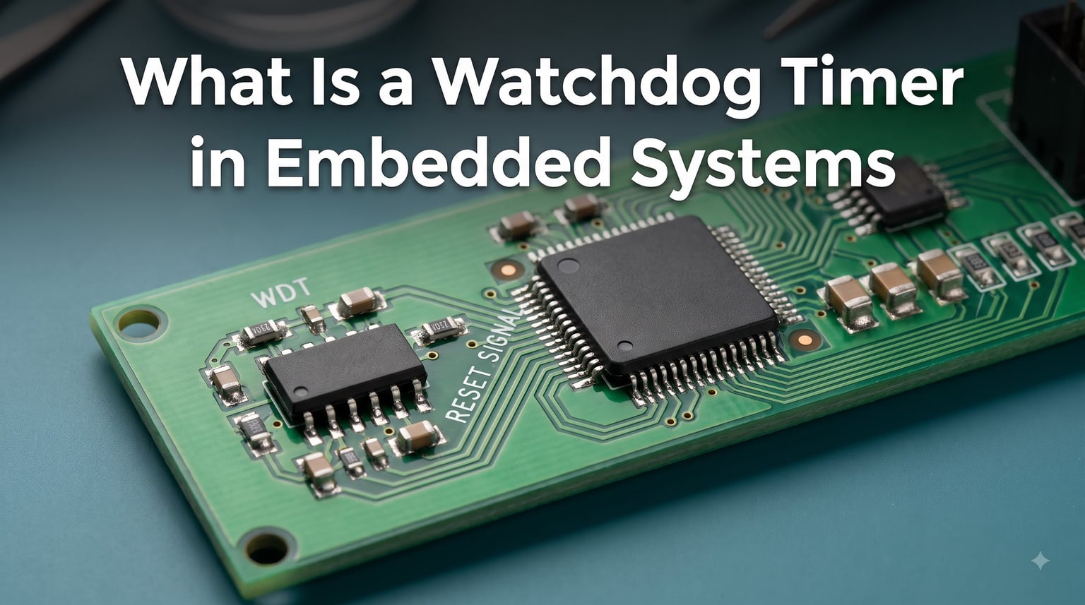
A watchdog timer in embedded systems is an independent hardware or software timer that monitors microcontroller operation and automatically resets the processor when software hangs, crashes, or stops responding. The watchdog counts down from a preset value and must be periodically reset, or “kicked,” by the main firmware. If the firmware fails to kick the watchdog before the countdown reaches zero, the watchdog asserts a reset signal and reboots the system.
The key phrase here is independent hardware. A watchdog timer is deliberately built as a separate circuit, either inside the microcontroller or as an external IC, so that a software fault cannot disable it. If the same processor that crashed could also silence the watchdog, the recovery mechanism would be useless. This separation is what makes a watchdog timer so reliable in unattended or safety-critical applications.
The Core Definition
A watchdog timer is a countdown timer peripheral that runs independently from the main CPU. It starts at a programmed value and decrements on each clock cycle. The firmware must write to a specific register or toggle a pin before the timer reaches zero. When the firmware performs this action on time, the timer reloads and the countdown restarts. When the firmware fails to act, the watchdog fires and forces a system reset.
Why Independent Hardware Matters
Most microcontrollers include a built-in watchdog peripheral driven by a separate clock source, often a low-power internal oscillator. This means the watchdog keeps running even when the main CPU is stalled, stuck in an infinite loop, or has suffered a clock failure. Without this independence, a software bug could disable the very mechanism meant to recover from it.
Kick the Dog: The Industry Metaphor
Engineers commonly say they “kick the dog,” “feed the watchdog,” or “pet the watchdog” when they reset the timer. The metaphor comes from the idea that if you stop paying attention to a watchdog, it will bite. These phrases appear throughout vendor documentation and code comments, so do not be surprised when you see them in production firmware.
How Watchdog Timers Work Step by Step
The watchdog timer operation follows a strict four-phase cycle. Understanding each phase helps you design firmware that survives real-world faults. Let me walk you through what happens from power-on to recovery.
Step 1: Initialization and Configuration
During system startup, the firmware configures the watchdog peripheral. This typically involves setting a timeout value, choosing a clock source, and selecting a prescaler that divides the clock down to a usable rate. For example, on an STM32 running at 32 kHz LSI clock with a prescaler of 64, you get 512 µs per counter tick. A reload value of 4,000 gives you roughly two seconds before reset.
Step 2: Periodic Kicking From the Main Loop
The main firmware must kick the watchdog periodically. This is usually done by writing a magic value to a specific register. On many ARM Cortex-M parts, you write 0xAAAA followed by 0x5555 to the watchdog refresh register. The kick should happen from the main loop or a high-priority task, never from inside an interrupt service routine.
Step 3: Timeout Detection
If the firmware fails to kick the watchdog within the configured window, the counter reaches zero. At that point, the watchdog peripheral asserts either an interrupt or a reset signal. In interrupt mode, the firmware gets one last chance to log diagnostic data before the system resets. In reset mode, the watchdog forces an immediate microcontroller reset.
Step 4: System Reset and Recovery
After the watchdog fires, the microcontroller goes through its normal reset sequence. The firmware boots, checks a reset-cause register to confirm a watchdog reset, logs the event if logging is available, and resumes normal operation. This automatic recovery is the entire point of using a watchdog timer in embedded systems.
The Countdown Mechanism Explained
The countdown is driven by an internal counter that decrements with each clock tick. The clock source is usually a low-frequency oscillator running at 32 kHz or 128 kHz, independent of the main system clock. This independence ensures the watchdog continues counting even if the main oscillator fails or the PLL unlocks. Some advanced MCUs allow the watchdog to operate from the main clock, but this is generally discouraged for production designs.
Types and Modes of Watchdog Timers
Not all watchdog timers are created equal. Modern embedded systems give you several options, each with specific trade-offs. Choosing the right type depends on your reliability requirements, certification needs, and system architecture.
Internal vs External Watchdog Timers
An internal watchdog timer is built into the microcontroller itself and accessed through memory-mapped registers. An external watchdog timer is a standalone IC like the TPS3851 or MAX6363 that monitors a toggle pin from the MCU. Internal watchdogs are cheaper and easier to use, while external watchdogs provide protection even if the entire microcontroller fails catastrophically.
Hardware vs Software Watchdogs
A hardware watchdog is a physical timer circuit. A software watchdog is a task running on the main processor that monitors other tasks, usually in an RTOS environment. Software watchdogs can catch task-level deadlocks that hardware watchdogs miss, but they share the same processor, so they can be disabled by a serious fault. The best designs use both: a hardware watchdog as the last line of defense and a software watchdog for finer-grained monitoring.
Window Watchdog Mode
A window watchdog enforces both a lower and upper time bound on the kick. If you kick too early, the watchdog fires. If you kick too late, it also fires. This catches bugs where the firmware gets stuck in a tight loop kicking the watchdog too frequently, a common mistake when developers place the kick inside a fast-running interrupt. STM32, NXP, and Microchip parts all offer window watchdog variants.
Task-Level Watchdogs in RTOS
When running FreeRTOS, Zephyr, or similar RTOS, you can add a task watchdog that monitors individual threads. Each task must signal a watchdog task within a deadline, or the system resets. This is essential in complex RTOS designs because a hardware watchdog alone cannot tell which task is hung. Memfault’s guide on watchdog best practices covers this approach in detail.
Watchdog Timer Implementation Examples
Theory is useful, but real engineers need working code. Below are three implementation examples covering the most common microcontroller families. Each example shows initialization, the kick function, and how to check the reset cause.
Basic Implementation Pattern
The simplest watchdog pattern uses a single flag set in the main loop and cleared by a background task. If the background task fails to run, the main loop stops clearing the flag, and the hardware watchdog eventually fires. This pattern works across virtually any platform.
// Pseudocode for basic watchdog pattern
void main(void) {
    watchdog_init(2000); // 2 second timeout
    system_init();
    while (1) {
        if (system_healthy) {
            watchdog_kick();
        }
        process_main_tasks();
        sleep_ms(100);
    }
}
STM32 HAL Watchdog Example
STM32 microcontrollers use the IWDG (Independent Watchdog) and WWDG (Window Watchdog) peripherals. The HAL library provides ready-to-use functions. The code below configures a 1-second timeout using the LSI clock.
// STM32 IWDG initialization
IWDG_HandleTypeDef hiwdg;
hiwdg.Instance = IWDG;
hiwdg.Init.Prescaler = IWDG_PRESCALER_64;
hiwdg.Init.Reload = 4095;
hiwdg.Init.Window = 4095;
HAL_IWDG_Init(&hiwdg);

// Kick the watchdog
HAL_IWDG_Refresh(&hiwdg);
ESP32 Watchdog Example
The ESP32 includes three watchdog timers: the interrupt watchdog, the task watchdog, and the main TWDT. The Arduino framework exposes these through simple functions, but you can configure them more finely using the ESP-IDF.
// ESP32 Arduino watchdog setup
#include <esp_task_wdt.h>
#define WDT_TIMEOUT 5 // seconds

void setup() {
    Serial.begin(115200);
    esp_task_wdt_init(WDT_TIMEOUT, true);
    esp_task_wdt_add(NULL);
}

void loop() {
    esp_task_wdt_reset();
    // your code here
}
Nordic nRF52 Watchdog Example
The nRF52 uses the NRF_WDT peripheral with eight independently configurable reload requests. Each RR register can be tied to a different firmware subsystem, which lets you monitor multiple tasks without an RTOS.
// Nordic nRF52 WDT configuration
nrf_wdt_behaviour_t behaviour = {
    .timeout = NRF_WDT_TIMEOUT_2000MS,
    .halt_on_debug = false,
    .pause_on_halt = false,
};
nrf_wdt_reload_request_enable(NRF_WDT_RR0);
nrf_wdt_behaviour_set(&behaviour);
nrf_wdt_enable();

// Kick from RR0
nrf_wdt_reload_request_set(NRF_WDT_RR0);
Best Practices for Watchdog Timer Configuration
A poorly configured watchdog is worse than no watchdog at all. It can fire during normal operation, causing more problems than it solves. These best practices come from years of debugging production firmware across consumer, industrial, and medical products.
Choosing the Right Timeout Value
The timeout should be longer than your longest legitimate operation. If you do a sensor read that takes 500 ms in worst-case conditions, set the watchdog to at least 1 second. Add margin for clock variation and temperature effects. Too short, and you get spurious resets. Too long, and you lose the responsiveness benefit of the watchdog.
Placement of the Kick Function
Place the kick in the main loop after all critical subsystems have been verified healthy. Never place the kick inside an interrupt service routine because ISR bugs become much harder to debug. A common pattern is to set a “system healthy” flag in each background task and only kick the watchdog when all flags are set.
Debug Mode Considerations
Disable the watchdog during development, or configure it with a very long timeout. Otherwise, the watchdog will fire every time you pause execution with a debugger. Most MCUs provide a halt-on-debug option for the watchdog that pauses the timer when the core is halted. Enable this feature whenever possible.
Logging and Diagnostics
Always log watchdog resets. Store the reset cause, last known task state, and any pending error flags to non-volatile memory before the watchdog fires. This information is invaluable when debugging field failures. Use a small EEPROM section or a dedicated log buffer in flash.
Watchdog Testing and Validation Strategies
Testing your watchdog implementation is not optional. A watchdog that never fires in the field has not been tested properly. Here are two strategies I use to validate watchdog behavior without bricking production hardware.
Intentional Fault Injection
During development, deliberately insert infinite loops and deadlock conditions to verify the watchdog fires as expected. Use a debugger to confirm the reset sequence runs correctly and the firmware recovers to a known-good state. Repeat this test across all operating modes, including low-power sleep and active run modes.
Hardware-in-the-Loop Testing
Automated test rigs can simulate sensor failures, communication timeouts, and processor faults. A proper HIL test runs through dozens of fault scenarios and confirms the watchdog recovers from each one. This is a requirement for ISO 26262 and IEC 61508 certification, and it dramatically reduces field failures in less regulated industries too.
Common Watchdog Pitfalls and Limitations
Watchdog timers are not a silver bullet. Understanding their limitations helps you design a more robust system and avoid false confidence in your fault recovery.
Limitations of Watchdog Timers
A watchdog cannot catch every fault. It cannot detect logic errors that produce wrong outputs but allow the firmware to keep running. It cannot catch memory leaks that slowly degrade performance. It cannot recover from permanent hardware failures. Treat the watchdog as a last resort, not a primary defense.
Watchdog in Bootloader Scenarios
Firmware updates require careful watchdog coordination. If the application watchdog fires during a flash erase operation, the bootloader may not be able to recover. Disable the watchdog during bootloader operation, or use a separate bootloader watchdog with a longer timeout. Reddit threads on watchdog in bootloader scenarios highlight this as a frequent source of field failures.
Safety-Critical Applications
In automotive, medical, and aerospace systems, watchdog timers are not optional. They are required by functional safety standards and must meet strict performance criteria.
ISO 26262 and IEC 61508 Compliance
ISO 26262 for automotive and IEC 61508 for industrial systems both require watchdog timers for ASIL and SIL rated components. The watchdog must be independent from the main processor, must have a known maximum response time, and must be tested for diagnostic coverage. These standards also require window watchdogs for higher safety integrity levels.
Medical and Aerospace Use Cases
Medical devices follow IEC 62304 and FDA guidance that mandate watchdog supervision for any life-supporting or life-sustaining function. Aerospace systems follow DO-178C, which requires evidence of fault detection and recovery. In all these domains, the watchdog is paired with comprehensive diagnostic coverage and rigorous testing. Robotics platforms that demand high embedded systems reliability often adopt similar watchdog architectures even outside regulated industries.
Frequently Asked Questions
What is the purpose of a watchdog timer?
A watchdog timer automatically detects software faults and recovers the system by issuing a reset when the firmware fails to respond within a defined time window. This allows unattended embedded devices to recover from hangs, infinite loops, and deadlocks without human intervention, making it essential for remote, mission-critical, and safety-critical applications.
How does a watchdog timer work?
A watchdog timer counts down from a programmed value using an independent clock source. The firmware must periodically reset this counter, an action called kicking or feeding the watchdog. If the firmware fails to reset the counter before it reaches zero, the watchdog peripheral asserts a reset signal and reboots the microcontroller, recovering it from the fault state.
What is an example of a watchdog timer?
A common example is the STM32 IWDG peripheral, which counts down from a 12-bit reload value using the 32 kHz LSI oscillator. Another example is the Nordic nRF52 WDT, which supports up to eight independent reload requests for monitoring multiple firmware subsystems. External examples include the Texas Instruments TPS3851 and Maxim MAX6363 watchdog supervisor ICs.
Is a watchdog timer always necessary?
A watchdog timer is essential for any embedded system that must operate unattended, recover from faults automatically, or meet safety certification requirements. It is highly recommended for remote devices, automotive ECUs, medical equipment, and industrial controllers. Simple consumer devices with easily accessible reset buttons may skip the watchdog, but production firmware benefits from one in nearly every case.
What happens when a watchdog timer expires?
When a watchdog timer expires, the peripheral issues either an interrupt or a reset signal depending on configuration. In interrupt mode, the firmware gets a final opportunity to save diagnostic data before a forced reset. In reset mode, the watchdog immediately resets the microcontroller, causing the firmware to restart from its initialization code. The reset cause register then indicates a watchdog-triggered reset for diagnostics.
How do I choose a watchdog timeout value?
Choose a timeout longer than your longest legitimate operation, including worst-case clock variation and temperature drift. A common rule is to set the timeout at twice the expected maximum task cycle time. For example, if your main loop runs every 200 ms in normal conditions, a 1-second watchdog timeout provides good safety margin while still recovering quickly from real faults.
Conclusion
A watchdog timer in embedded systems is the single most cost-effective reliability feature you can add to your firmware. It costs almost nothing, requires only a few lines of code, and it has saved countless field-deployed devices from becoming e-waste. From the Mars Pathfinder to modern IoT sensors, watchdog timers have proven their value across decades of embedded design.
Start by adding a basic hardware watchdog to your next project, configure the timeout based on your longest task cycle, and place the kick only when your system is verified healthy. Test the recovery path with intentional fault injection. Once you have that foundation, add a task-level watchdog if you are running an RTOS, and consider a window watchdog for safety-critical applications. Your future self, debugging a field failure at 2 a.m., will thank you.