
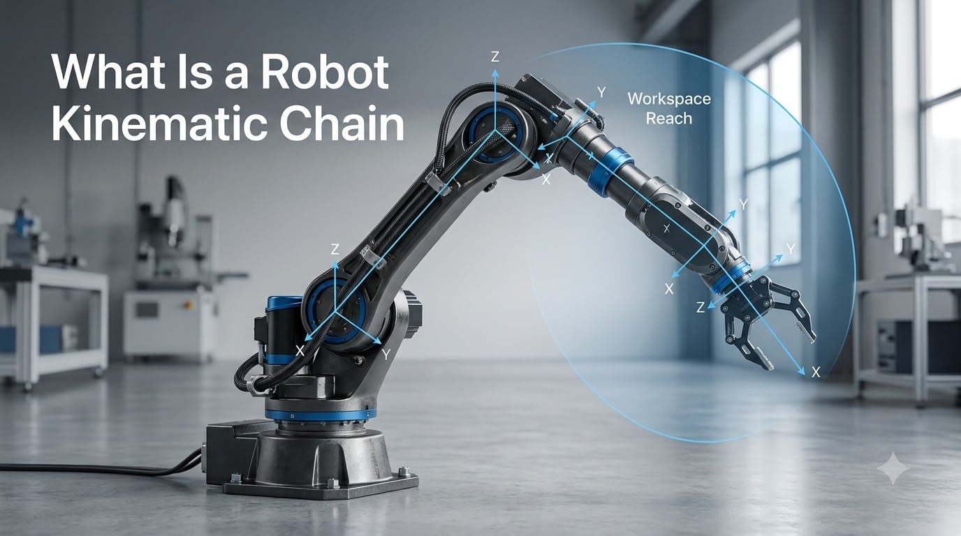
A robot kinematic chain is a series of rigid links connected by joints that transfers motion and force from a robot’s base to its end effector. Each joint adds a degree of freedom, and the full chain determines how a robot arm or leg can reach, rotate, and position itself in space.
If you are building, programming, or studying robots, the kinematic chain is the single concept you cannot skip. It sits underneath every movement a robot makes, from a factory welding arm swinging into position to a surgical robot guiding a needle with sub-millimeter accuracy. Our team has spent years working with robot manipulators, and we keep coming back to the same foundational idea: the chain of links and joints defines what a robot can physically do.
This guide breaks down what a robot kinematic chain is, how it works, the types of joints and chain structures involved, and how engineers use forward kinematics and inverse kinematics to control robot motion. We also cover real-world configurations, singularities, and practical applications so you walk away with both the theory and the context.
Whether you are a student tackling your first robotics course or an engineer integrating a manipulator into an automation line, the concepts below apply directly. We wrote this to be the resource we wish we had when starting out: technically accurate, grounded in real hardware, and free of unnecessary jargon. Let us start with the fundamental definition.
Table of Contents
What Is a Robot Kinematic Chain?
A robot kinematic chain is the connected sequence of rigid bodies (links) and movable connections (joints) that form the mechanical structure of a robot manipulator. The chain begins at a fixed base, passes through one or more links and joints, and terminates at a tool or end effector that interacts with the environment.
The word “kinematic” tells you this framework focuses on motion, geometry, and position, without considering the forces and masses that cause the motion. That separation matters. Engineers solve the geometry problem first, determining where each point of the robot is at any given time, and then tackle dynamics later. This layered approach keeps robot control manageable.
Think of your own arm as a kinematic chain. Your shoulder, elbow, and wrist are joints. The bones between them are links. When you reach for a coffee cup, your brain solves an inverse kinematics problem, figuring out what joint angles will place your hand at the cup. A robot does the same thing mathematically.
Every robot kinematic chain has a specific number of degrees of freedom, determined by how many joints it has and what type each joint is. Those degrees of freedom dictate whether the robot can reach a point in space from one direction or many, and whether it can rotate a tool to any orientation.
The kinematic chain concept comes directly from classical mechanics, specifically the study of mechanisms and machines. In mechanical engineering, a kinematic chain is any assembly of rigid bodies connected by joints that produces constrained motion. Robotics narrows this broad definition to focus on chains designed for controlled manipulation or locomotion. The key insight is that once you know the chain structure, you can write equations that predict exactly where the robot will be for any set of joint values.
Basic Components: Links and Joints
Every kinematic chain, no matter how complex, is built from just two types of components. Understanding these building blocks makes it far easier to analyze any robot you encounter.
Links: The Rigid Bodies
Links are the rigid bodies in a kinematic chain. They hold their shape under load and connect joints to one another. A link can be long, short, curved, or boxy. What matters mechanically is that it does not bend or compress during normal operation.
In practice, links also carry motors, cables, sensors, and sometimes gearboxes. The joint mechanics inside modern robots often integrate gear reduction systems directly into the link structure to save space and improve torque output. This integration is one reason industrial arms can deliver high payload capacity without enormous external motors.
Link stiffness directly affects robot precision. If a link flexes under load, the end effector moves away from its commanded position. Engineers specify link materials and cross-sections to keep deflection within acceptable limits. Carbon fiber and aluminum alloys are common choices for high-performance arms because they combine light weight with high stiffness.
Joints: The Connections That Enable Motion
Joints are the movable connections between links. Each joint constrains motion to a specific pattern, such as rotation around an axis or sliding along a line. Without joints, a robot would be a rigid statue. With them, the chain gains the ability to move through space in controlled ways.
The type and arrangement of joints determines the kinematic chain’s character. Two robots with identical link lengths but different joint configurations will have completely different workspaces and motion capabilities. This is why joint selection is one of the earliest and most consequential design decisions in robot development.
Each joint in a kinematic chain is typically actuated, meaning it has a motor or actuator driving its motion. The actuator can be an electric servo motor, a stepper motor, a hydraulic cylinder, or a pneumatic actuator. The choice of actuator affects the robot’s speed, precision, payload, and cost. Electric servos dominate modern industrial and service robots because they offer excellent controllability and energy efficiency.
Types of Joints in a Robot Kinematic Chain
Robot kinematic chains almost exclusively use two types of joints. There are six possible lower-pair joints in classical mechanics, but revolute and prismatic joints cover the vast majority of practical robot designs.
1. Revolute Joints (Rotational)
A revolute joint allows rotation around a single fixed axis. Think of a door hinge. The two connected links rotate relative to each other, and the joint has one degree of freedom described by an angle. Most industrial robot arms use revolute joints because they mimic biological joints like shoulders and elbows.
Revolute joints are typically powered by electric motors paired with gearboxes. A standard 6-axis industrial arm like the FANUC LR Mate uses six revolute joints stacked in a specific configuration to achieve a wide reach and flexible wrist orientation. The gear ratio between the motor and the joint amplifies torque while reducing speed, giving the robot the strength to lift heavy parts.
One practical consideration with revolute joints is joint range. Mechanical stops, cable routing, and physical interference between links limit how far each joint can rotate. These limits directly affect the robot’s reachable workspace. When engineers specify a robot for an application, they check that every required position falls within the joint ranges, not just within the theoretical reach.
2. Prismatic Joints (Linear)
A prismatic joint allows linear sliding motion along a single axis. Instead of rotating, one link slides relative to the other. Cartesian robots, also called gantry robots, use three perpendicular prismatic joints to move in X, Y, and Z directions. SCARA robots typically combine revolute joints with a single vertical prismatic joint.
Prismatic joints provide precise linear positioning and are common in pick-and-place systems, 3D printers, and CNC machines. They trade the compact envelope of a revolute joint for straightforward linear control. Linear guides, ball screws, and belt drives are the typical mechanical implementations behind prismatic joints.
Other Joint Types (Rare in Practice)
Spherical joints (ball-and-socket), cylindrical joints, helical joints, and planar joints exist in theory but rarely appear in standard robot manipulators. When they do, they are usually approximated by combining multiple revolute or prismatic joints at a single point. A robot wrist, for instance, often places three revolute joints together at a single location to approximate spherical motion. This approach gives engineers full control over each axis independently while achieving the same motion capability.
Helical joints, which combine rotation with linear translation like a screw, appear in some specialized mechanisms but are usually modeled as prismatic joints for kinematic analysis. The practical lesson: if you understand revolute and prismatic joints, you can analyze nearly any robot kinematic chain you will encounter.
Degrees of Freedom in a Kinematic Chain
Degrees of freedom (DOF) refer to the number of independent parameters needed to fully describe the configuration of a kinematic chain. Each joint contributes its own DOF to the total. A chain with six revolute joints has six degrees of freedom, meaning six independent joint variables define the robot’s posture.
To position and orient an end effector freely in 3D space, a robot needs at least six degrees of freedom: three for position (X, Y, Z) and three for orientation (roll, pitch, yaw). That is why classic industrial arms are designed with six joints. They can reach any point within their workspace at any tool orientation.
Robots with fewer than six DOF cannot access every orientation at every position. They are cheaper and simpler, which makes them ideal for tasks like vertical assembly or planar pick-and-place where full 3D orientation is not required. A 4-axis SCARA robot, for example, positions parts in X-Y-Z but only rotates the tool around the vertical axis.
Robots with more than six DOF are called kinematically redundant. The extra joints let the robot reach around obstacles or avoid bad postures. Humanoid arms often have seven degrees of freedom, matching the human arm, to achieve this kind of flexibility. Redundancy is also valuable in cluttered environments where a 6-DOF arm might be blocked but a 7-DOF arm can reconfigure its elbow to find a clear path.
The mobility formula, derived from Grubler’s equation, lets engineers calculate the theoretical DOF of a kinematic chain from its number of links, joints, and joint types. For a simple serial chain, the DOF equals the sum of each joint’s individual contribution. For parallel chains with closed loops, the calculation becomes more involved because constraints from multiple paths reduce the total freedom.
Serial vs Parallel Kinematic Chains
Kinematic chains come in two fundamental structures, and the choice between them shapes everything about a robot’s performance, payload, and workspace.
Serial Kinematic Chains (Open Loop)
A serial kinematic chain is an open-loop structure where each link connects to the next in a single sequence from base to end effector. Standard industrial robot arms like 6-axis articulated robots and SCARA robots are serial chains. The joints stack one after another.
Serial chains offer a large workspace relative to their footprint and can reach into confined spaces. They are also straightforward to model mathematically, since each transformation applies sequentially from base to tip. The tradeoff is that each link must support everything downstream, which means errors and deflections accumulate. Payload capacity is limited by the cascading structure, and the motors at the base must be powerful enough to move the entire arm plus payload.
Parallel Kinematic Chains (Closed Loop)
A parallel kinematic chain uses multiple chains connecting the base to a single moving platform. The Delta robot, with its three arms converging on a central platform, is the most recognizable example. The Stewart platform, used in flight simulators, is another well-known parallel architecture.
Parallel chains distribute loads across multiple paths, which gives them high stiffness and excellent payload-to-weight ratios. They also achieve very high speeds because the actuators stay near the base and do not need to move each other’s mass. However, their workspace is smaller relative to their overall size, and their kinematic equations are significantly more complex. Forward kinematics for a parallel robot can be harder to solve than inverse kinematics, which is the opposite of the serial case.
Serial vs Parallel: Quick Comparison
Serial chains win on workspace size and modeling simplicity. Parallel chains win on stiffness, speed, and payload efficiency. Most general-purpose industrial robots are serial, while high-speed pick-and-place and precision positioning tasks favor parallel designs.
Some robots combine both approaches. A hybrid kinematic chain might use a parallel mechanism for the shoulder and a serial chain for the wrist, gaining advantages from both structures. These designs are less common but appear in specialized applications where standard serial or parallel architectures cannot meet all requirements.
Forward Kinematics vs Inverse Kinematics
Once a kinematic chain exists, engineers need to solve two core problems to control it. These two problems, forward kinematics and inverse kinematics, are the practical heart of robot motion control.
Forward Kinematics
Forward kinematics asks: given the known joint angles (or displacements), where is the end effector? You plug joint values into kinematic equations and calculate the resulting position and orientation in Cartesian space. This problem always has a single, unique solution for a serial chain.
Forward kinematics is computationally straightforward. Engineers use homogeneous transformation matrices, often parameterized with the Denavit-Hartenberg (DH) convention, to multiply frame-to-frame transformations from base to tip. The result is a single 4×4 matrix describing the end effector’s pose. The DH convention assigns a coordinate frame to each link according to specific rules, reducing the number of parameters needed to describe each joint from six to four.
Inverse Kinematics
Inverse kinematics asks the reverse question: given a desired end effector position and orientation, what joint values will achieve it? This is the problem a robot controller solves constantly during operation, because users specify targets in task space, not joint space.
Inverse kinematics is harder. For a 6-axis arm, there may be zero solutions (the target is out of reach), one solution, or multiple solutions. Some configurations have infinite solutions when the robot is redundant. Solvers use either analytical methods, which produce closed-form solutions for specific robot geometries, or numerical iterative methods that work for any structure but are slower and may not converge.
Analytical solvers are preferred when available because they are fast and deterministic. Most 6-axis industrial arms with a spherical wrist have known analytical solutions. Numerical methods like Jacobian pseudoinverse or cyclic coordinate descent become necessary for robots without analytical solutions or when constraints like joint limits must be respected during solving.
Why Both Matter
Forward kinematics is used for simulation, monitoring, and collision checking. Inverse kinematics is used for trajectory generation and real-time motion commands. In practice, forum discussions consistently highlight inverse kinematics as the harder implementation challenge, especially when solutions fail to converge near singular configurations or when joint limits prevent reaching a target.
Many practitioners report that iterative solvers are more flexible but less predictable than analytical ones. If you are working with a standard industrial arm, an analytical solver will almost always be available. If you are building a custom robot with an unusual joint configuration, expect to rely on numerical methods and to spend time tuning them.
Common Robot Kinematic Chain Configurations
Different applications demand different kinematic chain arrangements. Here are the configurations you will encounter most often in the field.
6-Axis Articulated Arms
The 6-axis articulated arm is the workhorse of industrial robotics. Six revolute joints arranged in an anthropomorphic pattern give it full 6-DOF capability. These arms handle welding, painting, material handling, and machine tending across virtually every manufacturing industry. Major manufacturers like FANUC, ABB, KUKA, and Yaskawa all produce families of 6-axis arms spanning payloads from a few kilograms to over a thousand.
SCARA Robots
SCARA (Selective Compliance Assembly Robot Arm) robots use two parallel revolute joints plus a vertical prismatic joint. This gives them rigidity in the vertical direction and compliance in the horizontal plane. They excel at fast pick-and-place and assembly tasks, particularly inserting parts from above. Their simpler 4-DOF kinematics make them fast, affordable, and easy to program.
Delta Robots (Parallel)
Delta robots use three parallel kinematic chains connected to a single platform. They achieve extremely high speeds and accelerations, making them the standard choice for packaging and lightweight pick-and-place in food and pharmaceutical lines. Because the motors mount on the fixed base, the moving mass is very low, which is why Delta robots can complete hundreds of pick cycles per minute.
Cartesian (Gantry) Robots
Cartesian robots use three orthogonal prismatic joints for linear X-Y-Z motion. They offer simple kinematics, high precision, and large workspaces. You will find them in CNC machines, 3D printers, and automated storage systems. Their straightforward kinematic equations make them easy to program and their rectangular workspace is intuitive to work with.
Humanoid and Quadruped Limbs
Humanoid arms and legs are serial kinematic chains, typically with 6 to 7 degrees of freedom per limb. Quadruped robots like Boston Dynamics’ Spot use four serial leg chains for locomotion. These chains must handle both contact forces and dynamic motion, making their control especially demanding. The inverse kinematics for walking robots must be solved continuously as the support legs change and the body shifts weight.
Mobile robots also rely on kinematic analysis, though their chains are often simpler. The robot chassis kinematics for wheeled platforms involve differential drive or Ackermann steering models rather than articulated arms. These models describe how wheel velocities map to the robot’s overall position and heading.
Kinematic Singularities and Why They Matter
A kinematic singularity is a configuration where a robot loses one or more degrees of freedom. At a singular point, the robot cannot move its end effector in a certain direction regardless of how the joints move. This creates serious control problems.
The most intuitive example is a fully straightened arm. When all joints align, the end effector cannot move along the direction of the extended arm. The Jacobian matrix, which relates joint velocities to end effector velocities, becomes singular, meaning it cannot be inverted. Mathematically, the determinant of the Jacobian goes to zero, and the inverse kinematics problem has no solution in that direction.
Singularities matter because they cause instability, unpredictable motion, and failed inverse kinematics solutions near them. Robot controllers often slow down or refuse commands near singular configurations. Path planning software routes trajectories around singularities whenever possible.
There are three common types of singularities in 6-axis arms. Wrist singularities occur when two wrist axes align. Elbow singularities happen when the arm is fully extended or folded. Shoulder singularities arise when the first axis aligns with the wrist center. Each type blocks motion in a different direction, and operators learn to recognize and avoid them.
Forum discussions from practitioners consistently flag singularities as a real-world headache. Users report arms jerking, freezing, or producing errors when a planned path passes through or near a singular configuration. The practical advice: test trajectories in simulation first, and design tool paths that avoid known singular zones. Adding a seventh degree of freedom can eliminate most singularity problems by providing redundancy.
Mathematical Representation of Kinematic Chains
To control a kinematic chain computationally, engineers represent it with mathematical models. These models translate physical link lengths and joint axes into equations a computer can solve.
The Denavit-Hartenberg (DH) convention is the most widely used parameterization for serial kinematic chains. It assigns four parameters per joint: link length, link twist, link offset, and joint angle. For a 6-axis arm, that means 24 DH parameters fully describe the robot’s geometry. Once assigned, the parameters plug into standard transformation matrices that chain together from base to end effector.
The product of all individual joint transformation matrices yields the forward kinematics equation. This equation maps joint space (the set of all joint values) to Cartesian space (the end effector’s position and orientation). For inverse kinematics, you invert this mapping, which is where the mathematical difficulty arises.
The Jacobian matrix extends this model to velocity kinematics. It describes how small changes in joint values produce changes in end effector position. The Jacobian is essential for resolved-rate motion control, where a robot continuously adjusts joint velocities to track a desired Cartesian path. It also reveals singularities: when the Jacobian loses rank, the robot has entered a singular configuration.
Real-World Applications of Robot Kinematic Chains
Kinematic chains power robots across an enormous range of industries. Here is how they show up in practice.
Industrial Manufacturing
Factory floors are where kinematic chains are most visible. Welding robots use 6-axis arms to trace complex seam paths. Assembly robots place components with repeatability better than 0.1 mm. Paint robots use articulated chains to coat surfaces evenly while maintaining constant spray distance and orientation. The kinematic chain’s ability to follow precise trajectories at consistent speed is what makes these applications possible.
Surgical Robotics
Surgical robots like the da Vinci system use kinematic chains to translate a surgeon’s hand movements into precise instrument motions inside a patient’s body. These systems demand extremely accurate inverse kinematics, zero backlash, and motion scaling to achieve sub-millimeter precision. The kinematic chain includes additional mechanical features like remote center mechanisms that create a fixed pivot point at the incision.
Humanoid Robotics
Humanoid robots use full-body kinematic chains: arms for manipulation, legs for locomotion, and sometimes hands with multi-finger chains for grasping. Balancing and walking require solving kinematic and dynamic equations in real time across all limb chains simultaneously. The coordination of multiple chains makes humanoid control one of the hardest problems in robotics.
Space and Exploration
Mars rover robotic arms, satellite capture mechanisms, and the Canadarm on the ISS are all kinematic chains engineered for extreme reliability. These applications often require redundant degrees of freedom to ensure the robot can still complete its mission even if a joint fails. The kinematic models for space robots must also account for the lack of gravity when computing reachable workspace.
Service and Collaborative Robotics
Collaborative robots, or cobots, use kinematic chains designed to work safely alongside humans. Their joint torque sensors and compliant control modes build on kinematic models to detect and respond to contact. Service robots in logistics, agriculture, and healthcare all rely on kinematic chains adapted to their specific motion requirements, from bin picking to crop harvesting.
FAQs
What is the kinematic chain in robotics?
A kinematic chain in robotics is a sequence of rigid links connected by movable joints that transfers motion from a robot’s base to its end effector. Each joint contributes degrees of freedom, and the arrangement of joints and links determines the robot’s workspace, reach, and motion capabilities.
What is kinematics in robots?
Kinematics in robots is the study of motion without considering the forces that cause it. It focuses on the geometric relationship between joint positions and the position and orientation of the robot’s end effector, using mathematical models like homogeneous transformation matrices to describe how robots move through space.
What is an example of a kinematic chain?
Common examples of robot kinematic chains include the 6-axis articulated industrial arm (six revolute joints in series), the SCARA robot (two revolute joints plus one prismatic joint), the Delta robot (three parallel chains driving a central platform), and the Cartesian gantry robot (three perpendicular linear joints). A human arm is also a kinematic chain with shoulder, elbow, and wrist joints connected by bone links.
Who are the big 4 in robotics?
The ‘big 4’ in industrial robotics refers to the four largest robot manufacturers: FANUC, ABB, KUKA, and Yaskawa (Motoman). Together they account for the majority of industrial robot installations worldwide and produce a wide range of manipulators built around serial kinematic chains for manufacturing applications.
What is the difference between forward and inverse kinematics?
Forward kinematics calculates the end effector position from known joint angles, always producing a single unique answer. Inverse kinematics works in reverse, calculating the joint angles needed to reach a desired position, which can have zero, one, or multiple solutions. Inverse kinematics is the harder problem and is what robot controllers solve constantly during operation.
Why do kinematic chains have singularities?
Singularities occur when a robot’s joint axes align in a way that eliminates motion in one or more directions, causing the Jacobian matrix to lose rank. At a singularity, the robot cannot move its end effector along a specific path regardless of joint motion, which causes control instability and failed inverse kinematics solutions. Engineers avoid singularities through path planning and redundant joint design.
How many degrees of freedom does a robot need?
To position and orient an end effector freely in 3D space, a robot needs at least six degrees of freedom: three for position and three for orientation. Robots with fewer than six DOF are limited in what orientations they can achieve, while robots with more than six DOF are called redundant and can reach around obstacles or avoid singular configurations.
What software tools help with kinematic chain analysis?
Popular tools for kinematic chain analysis include MATLAB with the Robotics Toolbox, ROS (Robot Operating System) with MoveIt for motion planning, PyBullet and Gazebo for simulation, OpenRAVE for kinematic modeling, and Python libraries like ikpy and Pinocchio. These tools help engineers compute forward and inverse kinematics, visualize chains, and test trajectories before deploying to hardware.
Conclusion
Understanding what a robot kinematic chain is gives you the foundation for everything else in robotics. The chain of rigid links and movable joints defines a robot’s reach, precision, speed, and flexibility. From the six-axis arms on factory floors to the multi-limbed humanoid platforms under development, the same principles apply.
We covered the core components: links as rigid bodies, joints as the connections that enable motion, and the two joint types (revolute and prismatic) that dominate practical designs. We walked through degrees of freedom, the critical distinction between serial and parallel chain structures, the forward and inverse kinematics problems, common configurations, singularities, and the mathematical models that make all of this computable.
If you take away one idea, let it be this: the kinematic chain is the bridge between what a robot is physically built to do and what it can computationally achieve. Engineers who master kinematic analysis can design better robots, program them more effectively, and troubleshoot problems like singularities before they cause downtime.
For your next steps, dig deeper into the two problems that define day-to-day robot work. Study forward kinematics to understand how joint angles map to end effector positions, then tackle inverse kinematics to see how controllers actually drive robot motion. Practice with tools like ROS MoveIt or a MATLAB Robotics Toolbox model to reinforce the math with hands-on experience. The kinematic chain is where robotics theory meets real machines, and now you have the map.