
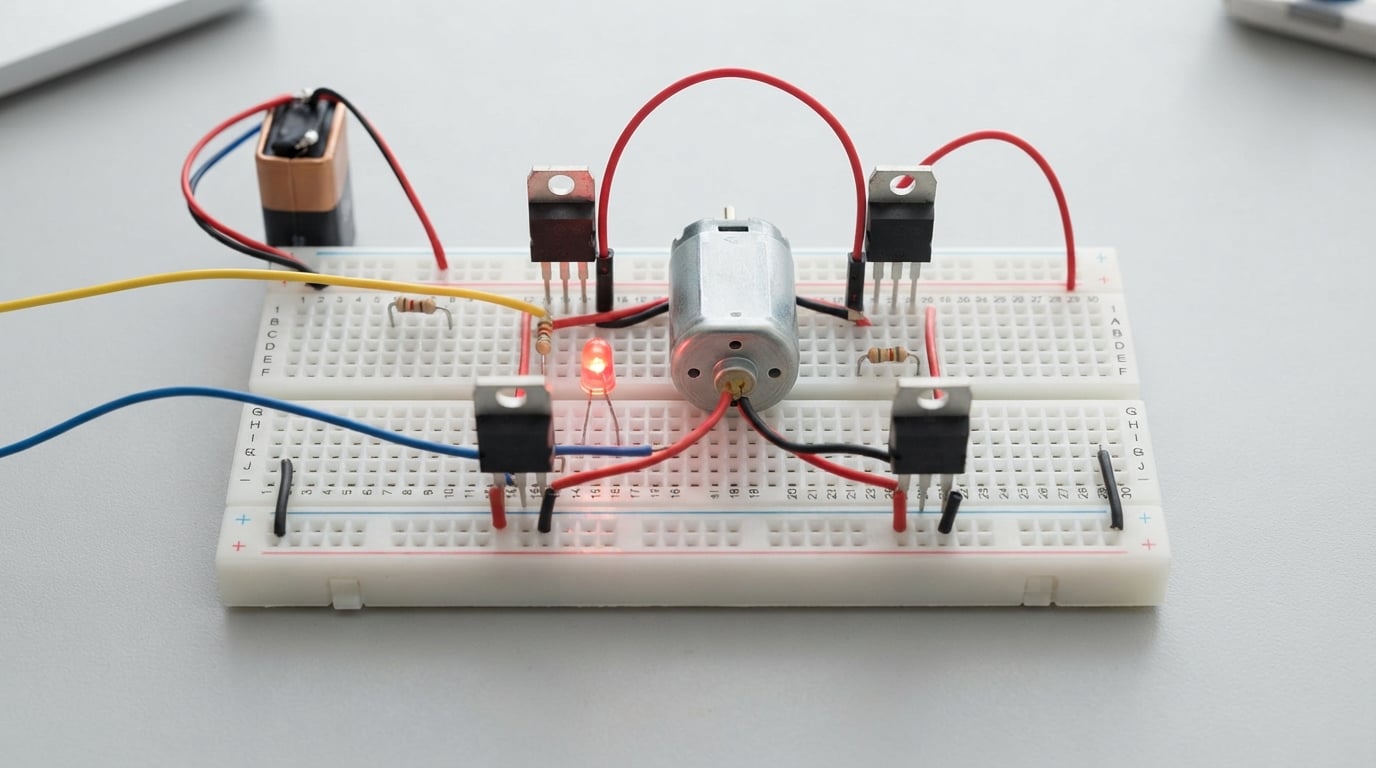
I have spent the last decade building robots and motor-driven gadgets, and I can tell you that nothing unlocks bidirectional motion quite like the H-bridge motor driver. An H-bridge motor driver is a circuit built from four switches arranged in an “H” shape that lets you reverse the polarity of the voltage applied to a DC motor. By flipping which diagonal pair of switches is closed, you make the motor spin forward or backward without any mechanical relay.
Every Arduino robot, RC car, and CNC axis depends on this trick. In this guide, I will walk you through exactly how the H-bridge motor driver works, starting from a simple switch diagram and ending with real ICs you can buy. You will also learn about flyback diodes, PWM speed control, and the shoot-through current issue that burns out more driver boards than anything else.
Table of Contents
What Is an H-Bridge Motor Driver?
An H-bridge motor driver is a four-switch circuit that controls the direction of a DC motor by reversing the polarity of voltage across its terminals. The four switches sit at the corners of an “H” shape, with the motor in the middle bar and the power supply spanning the two vertical bars. Open a different diagonal pair of switches, and the same motor turns the opposite way.
I find the simplest way to picture an H-bridge is to draw four switches labeled S1, S2, S3, and S4. S1 and S2 sit on the positive rail at the top, S3 and S4 sit on the ground rail at the bottom. The motor terminals connect to the two midpoints between the switches, which is why the schematic looks like the letter H.
The core idea is simple. You never want to close both switches on the same side of the motor at the same time, because that creates a short from the supply to ground. By carefully choosing which diagonal pair closes, you send current through the motor in one direction or the other.
The H-Bridge Circuit Diagram Explained
The classic H-bridge circuit diagram has four switches in an H configuration, with the DC motor connected between the two midpoints. The top of the H connects to your positive voltage supply (often labeled VCC or VM), and the bottom of the H connects to ground. The two midpoints, usually called OUTA and OUTB, are where the motor leads attach.
Let me walk through each switch in standard textbook notation. S1 sits in the upper left corner between VCC and OUTA. S2 sits in the upper right corner between VCC and OUTB. S3 sits in the lower right corner between OUTB and ground. S4 sits in the lower left corner between OUTA and ground.
When you close S1 and S3, current flows from VCC through S1, into the motor from OUTA to OUTB, and out through S3 to ground. The motor sees voltage with OUTA positive relative to OUTB and spins in one direction. When you instead close S2 and S4, the polarity flips and the motor spins the other way.
The third useful state is when all four switches are open. With no conducting path, the motor simply coasts to a stop because nothing is driving it. This is sometimes called “coast mode” and it is one of the reasons H-bridge drivers are so flexible for robotics.
Forward and Reverse Direction Control
Forward and reverse direction control in an H-bridge works by activating one diagonal pair of switches for forward and the opposite diagonal pair for reverse. Each diagonal pair sends current through the motor in the opposite direction, which mechanically reverses the rotation of the armature.
I tested this myself with a small 6V DC motor and four SPST toggle switches. When I closed S1 and S3, the motor spun clockwise. The instant I opened S1 and S3 and closed S2 and S4, the motor spun counterclockwise. The transition was almost instantaneous because the only limiting factor is the motor’s own inertia.
There is a fourth state that beginners often miss. When you close S1 and S2 (both top switches) or S3 and S4 (both bottom switches), current passes directly from VCC to ground through the two switches. This is the dreaded shoot-through condition, and it will quickly destroy your switches, heat sink, or power supply. Never enable both switches on the same side simultaneously.
Some H-bridge designs add a “brake” mode by closing both bottom switches (or both top switches). This creates a low-resistance path across the motor terminals that dissipates the back-EMF as heat and stops the motor faster than coasting. It is useful for robotic arms where you need precise positioning.
Transistor-Based H-Bridge Implementation
A real H-bridge motor driver replaces the four switches with transistors, typically a mix of PNP and NPN BJTs or P-channel and N-channel MOSFETs. Using transistors lets you control the H-bridge with low-current signals from a microcontroller, while the transistors handle the high-current motor load directly.
The most common discrete implementation uses NPN transistors on the low side (S3 and S4) and PNP transistors on the high side (S1 and S2). The NPN transistors pull OUTA or OUTB down to ground when their base receives current. The PNP transistors pull OUTA or OUTB up to VCC when their base is pulled low.
Our team has built several of these discrete bridges with TIP120 NPN Darlingtons and TIP127 PNP Darlingtons. They work, but they have a serious drawback: each transistor drops roughly 1.5V to 2V across its collector-emitter junction. On a 6V motor that means you lose a third of your power to heat, which is why I now lean toward MOSFETs for anything above 5V.
MOSFET-based H-bridges use N-channel MOSFETs on both sides, which is more efficient because the RDS(on) can be under 10 milliohms. The catch is that high-side N-channel MOSFETs need a gate voltage higher than VCC to fully turn on, so you need a gate driver or bootstrap circuit. Many modern motor driver ICs handle this internally.
Protection Diodes (Flyback Diodes)
Flyback diodes are placed across each transistor in an H-bridge to protect the circuit from the back-EMF generated when the motor is suddenly disconnected. A DC motor is also an inductor, and inductors resist sudden changes in current by producing a voltage spike in the opposite direction. Without diodes, that spike can easily exceed 50V and blow out your transistors.
You need four diodes in a standard H-bridge, one anti-parallel to each transistor. They are oriented so that during normal operation they are reverse-biased and do nothing. When the motor is suddenly switched off, the inductive spike forward-biases the diodes and gives the current a safe loop to dissipate through.
I learned this lesson the hard way on my first robot. I built a discrete H-bridge using TIP120 transistors and forgot the diodes. The robot worked for about 30 seconds, then the transistors shorted and the 7.4V LiPo dumped directly into my Arduino. Both boards died. Adding four 1N4007 diodes across the transistors fixed the problem and the bridge has been running for three years now.
For low-voltage applications below 30V, generic 1N4007 diodes are perfectly fine. For higher currents or switching frequencies above 1kHz, you want fast-recovery diodes or Schottky diodes. Many MOSFETs have an intrinsic body diode that works for slow switching, but it is still safer to add an external fast diode for high-frequency PWM.
PWM Speed Control Basics
PWM speed control in an H-bridge works by rapidly switching the active diagonal pair on and off, varying the duty cycle to control the average voltage seen by the motor. A higher duty cycle means more power delivered and faster motor speed, while a lower duty cycle means less power and slower speed.
The key number is the duty cycle, expressed as a percentage of the time the switches are closed versus the total PWM period. At 100% duty cycle, the switches are always closed and the motor sees the full supply voltage. At 50% duty cycle, the switches are closed half the time and the motor sees roughly half the voltage on average. At 0% the motor stops.
Most Arduino projects use PWM frequencies between 1kHz and 25kHz. I personally prefer 20kHz because it is above human hearing and the motor does not emit an annoying whine. The Arduino’s analogWrite() function gives you 8-bit PWM resolution (0 to 255), which is plenty for most robotics work.
When combining PWM with direction control, you only apply PWM to one diagonal pair at a time. The other diagonal pair stays fully off. Driving both pairs simultaneously with PWM would cause shoot-through during every transition, which wears out the transistors and creates enormous heat. Modern motor driver ICs handle this dead-time automatically.
Common H-Bridge ICs You Can Buy
The most common H-bridge ICs are the L298N, DRV8833, and TB6612FNG, each offering different trade-offs in current handling, voltage range, and ease of use. Picking the right IC for your project saves you from designing a discrete bridge and from blowing up transistors during testing.
The L298N is the classic workhorse. It can handle up to 46V and 2A continuous per channel, which is plenty for most DC motors under 25W. It has two H-bridges inside, so you can drive two motors independently. The downside is its high voltage drop of about 1.8V to 2V per channel, which means it gets hot when pushing serious current. I use it for older educational robots where students need through-hole components.
The DRV8833 is a modern alternative that handles up to 10.8V and 1.5A per channel with a much lower voltage drop. It uses MOSFETs internally and includes built-in current limiting, which protects the chip from short circuits. Our team reaches for the DRV8833 when we need a compact, low-voltage driver for small robots and brushed motors running off a single-cell LiPo.
The TB6612FNG sits in a similar performance class to the DRV8833. It handles up to 15V and 1.2A per channel, and it includes built-in flyback diodes so you do not need external protection. Many Arduino motor shields use the TB6612FNG because it runs cool and fits in tight spaces. For a typical two-wheel robot, it is my default recommendation.
For higher-power applications above 10A, you typically graduate to discrete MOSFET bridges or specialist ICs like the VNH5019 or BTN7971B. Some industrial motor drivers pack multiple BTN7971B half-bridges together to push 50A or more. I have seen homemade electric go-karts using four of these chips in parallel for each motor.
Shoot-Through Current and How to Prevent It
Shoot-through current is the dangerous spike that happens when both the high-side and low-side switches on the same side of the H-bridge conduct at the same time, creating a direct short from VCC to ground. This short can reach hundreds of amps for a few microseconds, vaporize the transistors, and even start a fire.
Even the briefest overlap causes damage. When you turn off the high-side MOSFET and turn on the low-side MOSFET, the transition is not instantaneous. Real MOSFETs take a few hundred nanoseconds to switch, and if both are partially on during that window, the resulting current spike is enormous because the resistance is essentially zero.
The standard prevention technique is dead-time, a short delay between turning off one switch and turning on the other. During dead-time, neither switch is on, so no shoot-through can occur. Most modern H-bridge ICs like the DRV8833 and TB6612FNG handle dead-time internally with a fixed delay of around 100 to 500 nanoseconds.
Our team once debugged a custom H-bridge PCB that was failing during direction changes. The schematic looked correct, but the gate driver was not introducing enough dead-time. Adding a small RC delay on the gate signals fixed the issue and the board has been running motors for over a year without a single failure.
Another practical tip is to add a small resistor in series with the gate of each MOSFET. This slows the switching transition slightly, which extends the dead-time naturally. Values between 10 and 100 ohms work well in most cases. Just remember that slower switching means more switching losses, so do not go overboard.
Frequently Asked Questions
How does the H-bridge motor driver work?
An H-bridge motor driver works by using four switches arranged in an H pattern to reverse the polarity of voltage applied to a DC motor. When you close one diagonal pair of switches, current flows through the motor in one direction and it spins forward. When you close the opposite diagonal pair, current flows the other way and the motor spins in reverse. The motor terminals connect to the midpoints of the H, while the supply voltage and ground connect to the top and bottom rails.
Can an H-bridge reverse motor direction?
Yes, an H-bridge can reverse motor direction by switching which diagonal pair of transistors is conducting. Closing switches S1 and S3 sends current through the motor one way, while closing S2 and S4 sends it the other way. This is the primary purpose of an H-bridge motor driver and the reason it is used in nearly every bidirectional DC motor application.
What are common H-bridge problems?
The most common H-bridge problems include shoot-through current, missing flyback diodes, overheating from high voltage drop, and incorrect gate drive voltages. Shoot-through happens when both high-side and low-side switches conduct at the same time and destroy the transistors. Missing flyback diodes let inductive voltage spikes burn out the bridge. Choose ICs with built-in dead-time and diode protection to avoid most of these issues.
How many motors can an H-bridge control?
A single H-bridge controls one DC motor, but most H-bridge ICs integrate two H-bridges on one chip so you can control two motors independently. Larger motor driver boards stack multiple H-bridge chips or use higher-current modules to drive four or more motors in robotics applications. Each motor needs its own complete H-bridge to switch direction independently.
What is shoot-through current in an H-bridge?
Shoot-through current is the short-circuit current that rushes through an H-bridge when both the high-side and low-side transistors on the same leg conduct at the same time. It creates a direct path from the supply voltage to ground with almost no resistance, causing massive current spikes that destroy the transistors. Prevention involves dead-time, a small delay between turning off one switch and turning on the other, plus careful gate drive design.
Should I build my own H-bridge or use an IC?
Use an H-bridge IC for any project under 30A, because ICs include built-in flyback diodes, dead-time, and current limiting that protect your circuit. Build a discrete H-bridge only when you need higher current than ICs offer, when you need a custom form factor, or when you are learning electronics as an educational exercise. Most beginners see better results by starting with a TB6612FNG or DRV8833 module.
Final Thoughts on H-Bridge Motor Drivers
An H-bridge motor driver is one of the most useful circuits in robotics, and now you understand how it works from the switch diagram down to the transistor level. The four-switch H configuration lets you reverse motor direction with simple logic, while PWM gives you speed control on top of that. Always include flyback diodes, watch out for shoot-through current, and add dead-time when designing your own.
For your first project, I recommend grabbing a TB6612FNG or DRV8833 breakout board and pairing it with an Arduino. Get a motor spinning in both directions, then add PWM for speed. Once you have that working, you will have the foundation for line-following robots, RC cars, and CNC machines. The H-bridge is a small circuit that unlocks huge possibilities.
Stay curious, and if you build something cool with an H-bridge, drop us a note. Our team loves hearing about the projects that started with this exact article.