
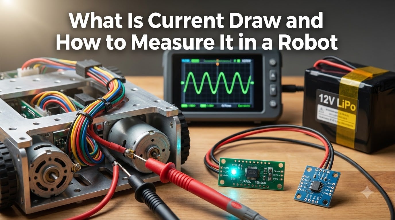
Current draw is the amount of electrical current a robot or its components pull from the power source during operation, and understanding it is the difference between a robot that runs for hours and one that dies in minutes. I learned this the hard way when my first differential drive robot kept browning out during turns, and tracing the problem back to a 22A inrush current taught me that measuring current draw is not optional for serious robot builders.
In this guide, I will walk you through what current draw is, why it matters for every robot you build, and the three practical methods I use on our team’s robots to measure it accurately. Whether you are wiring a small Arduino bot or a 30-pound competition robot, this is the foundation you need before you pick a battery, a motor driver, or a fuse.
Table of Contents
What Is Current Draw in a Robot
Current draw is the rate of electrical current flow that a robot component or entire system pulls from its power source, measured in amperes (amps or A). One ampere equals one coulomb of charge passing a point per second, and it represents how hard your battery has to work to keep your robot moving.
Think of current draw like water flowing through a pipe. Voltage is the pressure pushing the water, and current is the actual flow rate. A small sensor sipping power might draw only 0.02A (20 milliamps), while a stalled DC gear motor can pull 7A or more in a fraction of a second. Both numbers matter when you design a robot.
Why Current Draw Matters in Robotics
Measuring current draw tells you four critical things about your robot. First, it reveals whether your battery can sustain the load without voltage sag that causes brownouts. Second, it shows you whether your motor driver, wires, and connectors are rated for the actual load, not just the theoretical load. Third, it helps you detect mechanical problems like binding gears, stalled motors, or collisions that spike current abnormally. Fourth, it lets you predict battery life accurately instead of guessing from spec sheets.
Our team has used current monitoring to find everything from a stripped gear in a robot arm to a shorted LED that was draining a 12V battery overnight. If you cannot measure current, you are essentially flying blind on every power-related decision.
Key Current Draw Terms You Need to Know
Stall current is the current a motor draws when its shaft is held still while powered. It is the maximum current the motor will ever pull, and you should size your electronics to handle it safely.
Running current is the current a motor draws while spinning under normal load. For most DC gear motors, running current is 10-30% of stall current.
Inrush current is the brief spike that happens at the moment a motor starts moving from a standstill. It can be 2-3x the steady-state running current and lasts only milliseconds, but it can trip breakers and brown out your logic supply.
Steady state current is what your system settles into during constant operation. This is the number you use to calculate battery life.
Methods to Measure Current Draw in a Robot
There are three practical ways to measure current draw on a robot, and each has a place in your toolbox. I use all three depending on what I need to learn about the system.
Digital multimeter (DMM): The simplest method, perfect for one-time spot checks. You break the circuit and put the meter in series. Cheap, accurate, but cannot log data or capture fast transients.
Current sensor module (hall effect or shunt): Modules like the ACS712 or INA219 sit inline with your power wire and output an analog or I2C signal proportional to current. These are what you want for real-time monitoring and data logging, and they pair perfectly with Arduino and Raspberry Pi.
Oscilloscope with current probe: The only way to truly see what is happening with PWM-driven motors, switching regulators, and inrush spikes. A scope shows you the waveform, not just an average. It is overkill for hobbyists but essential for serious debugging.
Measurement Method Comparison
| Method | Best For | Accuracy | Cost Range | Data Logging |
|---|---|---|---|---|
| Digital Multimeter | Spot checks, simple DC | High (0.5-2%) | Budget | No |
| Hall Effect Sensor (ACS712) | AC/DC continuous monitoring | Medium (1-3%) | Budget to Mid | Yes (via microcontroller) |
| Shunt + Op-Amp (INA219) | DC battery monitoring | High (0.5-1%) | Budget to Mid | Yes (via I2C) |
| Oscilloscope + Current Probe | PWM, transients, noise | High (1-2%) | Professional | Yes (scope memory) |
| Inline USB Tester | Low-power USB robots | Medium (2-3%) | Budget | Some models |
How to Measure Current Draw with a Multimeter
A digital multimeter in current mode is the fastest way to get a current draw reading on a robot, but you must wire it in series, not parallel. Most beginners try to put the probes across a component like measuring voltage, and that creates a short circuit through the meter. Follow the steps below for a safe reading.
Step 1: Power Down the Robot and Disconnect the Battery
Always start with the system off. Remove the battery connector or unplug the main power lead before you touch anything. This prevents accidental shorts and protects your multimeter fuse if you set it up wrong.
Step 2: Move the Red Probe to the Amps or mA Jack
Most multimeters have separate jacks for voltage and current. The current jack is usually labeled “A” or “mA” and is fused. Plug your red probe in there, and leave the black probe in the common (COM) jack.
Step 3: Set the Meter to the Correct Current Range
Turn the dial to DCA (direct current amps) or mA. If you expect less than 200mA, use the mA range for better resolution. For a robot with motors, expect amps, not milliamps.
Step 4: Break the Circuit and Insert the Meter in Series
Disconnect the positive wire going from the battery to the component you want to measure. Connect the meter’s red probe to the battery side and the black probe to the component side. Current now flows through the meter on its way to the load.
Step 5: Power On and Read the Value
Reconnect the battery and observe the reading. If you see a negative number, reverse the probes. For motors under load, expect the current to fluctuate as the motor speed changes.
Multimeter Safety and Limitations
Most hobby multimeters have a 10A maximum range with a fuse, and exceeding it pops the fuse or damages the meter. Never try to measure current directly across a battery or power supply. Always go in series. Also, standard multimeters struggle with PWM motor currents because they average the readings, which gives you a misleadingly low number. If you need to see the true peak current of a PWM-driven motor, you need an oscilloscope or a peak-hold meter.
Using Current Sensors and Shunt Resistors for Continuous Monitoring
Current sensors are the workhorse of real-time current monitoring in robots, and they let you log data, trigger safety shutdowns, and even detect collisions by watching for current spikes. I have integrated current sensors into every competition robot I have built since 2019.
Hall Effect Current Sensors (ACS712)
The ACS712 family uses a hall effect sensor to measure the magnetic field around a conductor carrying current. The output is an analog voltage centered at VCC/2 (2.5V at 5V supply) that swings up or down based on current direction. Modules come in 5A, 20A, and 30A versions.
Wire the ACS712 in series with the positive line of whatever you want to monitor. Read the analog output with an Arduino ADC pin. The sensitivity is 185 mV/A for the 5A version, 100 mV/A for the 20A version, and 66 mV/A for the 30A version. At 0A, you will read 2.5V, so subtract that offset in your code.
The advantage of hall effect sensors is that they have no direct electrical connection to the measured circuit on the sensing side, so they are safer to use and can measure AC or DC. The downside is that they are less accurate at very low currents and can drift with temperature.
Shunt Resistor Sensors (INA219)
A shunt resistor is a small, precision resistor placed in series with the load. Current flowing through it creates a small voltage drop that you measure with an amplifier. The INA219 combines a shunt resistor and a 12-bit ADC on one tiny chip that talks I2C to your microcontroller.
Wire the INA219 in line with your battery’s negative lead (or positive, but negative is more common in robotics). It can measure up to 3.2A by default, and you can change the shunt resistor for higher ranges. Resolution is 0.1 mA, which is more than enough for most robot applications.
Shunt-based sensors are more accurate than hall effect sensors and have much lower temperature drift. They are the standard choice for battery current monitoring in serious robotics projects. Our team’s separate power for logic and motors guide explains why you should measure each rail separately with its own sensor.
Installing a Current Sensor in Your Robot
Place the current sensor as close to the battery as possible so you measure total system draw. Use appropriately gauged wire for the load (18 AWG for sensors, 12-14 AWG for motor lines) and keep the high-current path short. If you are measuring motor current specifically, place the sensor between the motor driver and the motor, not between the battery and the driver, to avoid capturing other system loads.
Oscilloscope Measurement for PWM Motor Currents
PWM motor control is the reason most multimeter current readings on robot motors are wrong. PWM rapidly switches the motor on and off at a fixed frequency (often 20 kHz), and a multimeter only sees the average of that switching. You will read something like 3A when the actual peak current during each on-pulse is 8A, and that mismatch is what causes burned-out drivers and tripped breakers.
An oscilloscope with a current probe (or a differential voltage probe across a shunt) shows you the actual waveform. You can see the peak current, the ripple frequency, and the decay between pulses. This is the only way to diagnose PWM-related current issues properly.
To measure PWM current with a scope, either clamp a current probe around one of the motor wires or insert a small shunt resistor (1 milliohm to 10 milliohms) in series with the motor and probe the voltage across it. Set your scope to AC coupling, adjust the timebase to show 2-4 PWM cycles, and trigger on the rising edge. You will see a sawtooth waveform that represents the current ramping up during the on-time and decaying during the off-time.
This technique is essential when designing or debugging motor drivers, but most hobbyists can skip it and rely on a current sensor module plus careful wire and fuse sizing instead. If you want to learn more about selecting the right wire gauge for your current levels, our robot power system wiring guide walks through the calculations.
Robot-Specific Applications of Current Draw Measurement
Current draw measurement is not a one-size-fits-all task in robotics. Different robot subsystems have different current signatures, and knowing what to expect helps you spot problems fast.
DC Gear Motors and Drive Trains
DC gear motors are the most common actuators in mobile robots, and their current draw tells you a lot about the drive system. A typical 12V DC gear motor with a 30:1 gear ratio might draw 0.5A running free, 2-3A under normal load, and 7-8A at stall. If you measure the motor at stall and it pulls significantly more or less than the datasheet number, the gearbox may be damaged or the motor may be faulty.
Measure drive train current with the robot on blocks first to capture the no-load current, then on the ground under normal driving conditions. The difference between these two readings is your rolling resistance, and a high rolling resistance reading points to bad bearings, misaligned wheels, or dragging brakes. This kind of testing is also how teams diagnose why their robot keeps browning out during aggressive maneuvers.
Stepper Motors
Stepper motors are unusual because their current draw stays relatively constant whether the motor is turning or holding position. A NEMA 17 stepper running at 1.5A per phase will pull 1.5A continuously as long as the coils are energized, which is why stepper-driven robots can heat up fast and drain batteries even when stationary.
Use a current sensor on each phase or on the main power input to the stepper driver. The relationship between current and torque is direct: τ = Kt × I, where Kt is the motor’s torque constant. If you need to know more about this relationship, our torque calculation guide covers the math in detail.
Servo Motors
Servos draw surprisingly high current when moving under load, and stacking multiple servos is one of the most common ways to brown out a robot. A single standard-size servo might pull 150-300mA idle, 500-800mA moving, and over 1.5A if stalled. Multiply that by 6 servos in a hexapod leg, and you can easily exceed 5A during a fast walk cycle.
Measure servo current at the servo power rail (usually 5-7V) using a current sensor. If you see current spikes above 1A per servo during normal operation, check for mechanical binding in the linkages. A stalled servo draws the same current as a free one under heavy load, so the only way to tell the difference is to watch the current pattern over time.
Battery Current Monitoring
For autonomous robots, the most important current measurement is total battery drain. Install a current sensor on the main battery line and log the data over time. This lets you calculate actual battery life, identify unexpected drains (like a sensor that fails to sleep), and predict when the robot will need to return to its charging station.
When choosing a battery, use your measured current draw to size the capacity correctly. As a rule of thumb, you want the battery’s C-rating to be at least 2x your peak current draw. Our battery selection guide walks through the capacity calculation step by step, and the battery chemistry comparison explains why different chemistries handle high current draws differently.
Collision and Grasp Detection
One of the most powerful tricks in robotics is using current spikes as a sensor. A robot arm’s gripper can detect that it has successfully grasped an object by watching for a sudden current increase in the gripper motor. A mobile robot can detect a collision by watching for an unexpected current spike in the drive motors when the robot should be moving freely.
This works because mechanical events translate directly into electrical load. A stalled motor pulls more current, a sudden stop creates a current spike, and a successful grasp causes the motor to work harder against the new load. Setting up these detections in code is straightforward once you have a current sensor streaming data to your microcontroller.
Safety Considerations for High-Current Robot Measurement
Measuring current in a high-power robot can be dangerous, and I have personally popped multimeter fuses, melted wire insulation, and triggered small fires by being careless. Follow these rules every time you measure current on a robot that pulls more than 5A.
Always use appropriately rated fuses on your main power line, sized just above your normal operating current but below the wire and connector limits. A 20A fuse on a 30A line is appropriate for most competition robots, while a 5A fuse on a small hobby robot prevents disasters.
Never measure current by holding a probe against a wire with your hand. Use proper test clips or have a friend hold the probes while you watch. Current measurement is in series with the load, and a loose probe can create an arc or cause the wire to move and short against something.
Disconnect the battery before inserting or removing any current sensor in the main power line. Hot-plugging a high-current shunt resistor or sensor can cause sparks and damage the sensor.
Wear safety glasses when working with LiPo batteries. A shorted LiPo can vent flame in seconds, and the combination of high current measurement and an unprotected LiPo is a real fire risk. Always use a fuse or circuit breaker in line with the battery.
Troubleshooting Common Current Measurement Errors
Even experienced builders get wrong current readings, and understanding the most common pitfalls saves hours of debugging. Here are the issues I see most often in forum posts and our own projects.
Why Your Multimeter Reads Lower Than Expected
If your multimeter reads 3A when the motor’s datasheet says 7A stall current, the most likely cause is that the motor is not actually stalled. Holding a motor still with your hand rarely creates a true stall condition. Use a bench vice or clamp for accurate stall testing.
The second most common cause is PWM. If your motor driver is running at a 50% duty cycle, the average current will be roughly half the peak current. Only a scope or a true RMS meter will give you the right number.
Why Your Voltage Drops When Motors Start
Voltage drop under motor load is normal and is caused by the internal resistance of the battery, wires, and connectors. If the voltage drops more than 10% when your motors start, you have undersized wiring, weak connectors, or a battery that cannot supply the current. This is one of the most common causes of robot brownouts.
Why Your Current Sensor Reads Zero When the System Is On
Check the orientation of the sensor first. Many current sensors have a marked direction for current flow, and reversing the wire can give you a negative or zero reading depending on how you wired it. Second, check that the sensor’s power supply is connected and that the output pin is wired to the correct ADC input on your microcontroller. Third, verify that the current is actually flowing through the sensor and not bypassing it through a parallel path.
Why Multiple Measurements Give Different Results
Current draw varies with load, motor speed, battery voltage, and temperature. Expect to see different numbers each time you measure, especially on a robot that accelerates, turns, and climbs. To get a meaningful baseline, take at least 5 measurements under the same conditions and average them.
Frequently Asked Questions About Current Draw in Robots
What is current draw measured in?
Current draw is measured in amperes (amps or A), which represents the rate of electrical charge flow. Smaller currents are measured in milliamps (mA), where 1A equals 1000 mA. Sensors and microcontrollers typically draw milliamps, while motors draw amps.
How do you measure the current draw of a device?
To measure the current draw of a device, you connect a multimeter, current sensor, or shunt resistor in series with the power supply and the device. Current must flow through the measuring instrument, so you break the circuit and insert the meter inline. The reading tells you how much current the device is pulling at that moment.
How do you measure current draw with a multimeter?
To measure current with a multimeter, first power off the circuit, then move the red probe to the amps jack and set the dial to DCA. Break the circuit on the positive wire and connect the red probe to the power source side and the black probe to the load side. Power the system back on and read the value in amps.
Can you measure power draw with a multimeter?
Yes, you can calculate power draw by multiplying the measured voltage by the measured current (P = V x I). Most digital multimeters can also measure power directly when in the right mode. For accurate power measurements, measure both voltage and current at the same time under stable load conditions.
How is current draw measured accurately on PWM motors?
PWM motor current cannot be measured accurately with a standard multimeter because the average reading hides the peak current during each PWM pulse. Use an oscilloscope with a current probe or measure the voltage across a small shunt resistor with the scope. The waveform reveals the true peak, average, and ripple current.
What is a normal current draw for a small robot?
A small hobby robot with an Arduino, two small DC gear motors, and a few sensors typically draws 200-500 mA while idle and 1-3A while driving. A medium robot with four 12V gear motors might draw 5-10A during normal operation and 20-30A at stall. Battery current monitoring is the best way to know your specific robot’s actual draw.
Conclusion
Measuring current draw is one of the most valuable skills in robotics, and it unlocks everything from proper battery sizing to collision detection. Start with a $20 digital multimeter for spot checks, add an INA219 or ACS712 module for continuous monitoring, and reach for an oscilloscope when you are debugging PWM issues or designing your own motor drivers.
I encourage you to spend an afternoon measuring the current draw of every subsystem in your current robot project. You will probably find at least one component that draws more than you expected, and that knowledge will save you debugging time on every project you build from here on. Combine these measurements with proper battery sizing and safe power wiring, and your robots will be more reliable from the first power-on.