
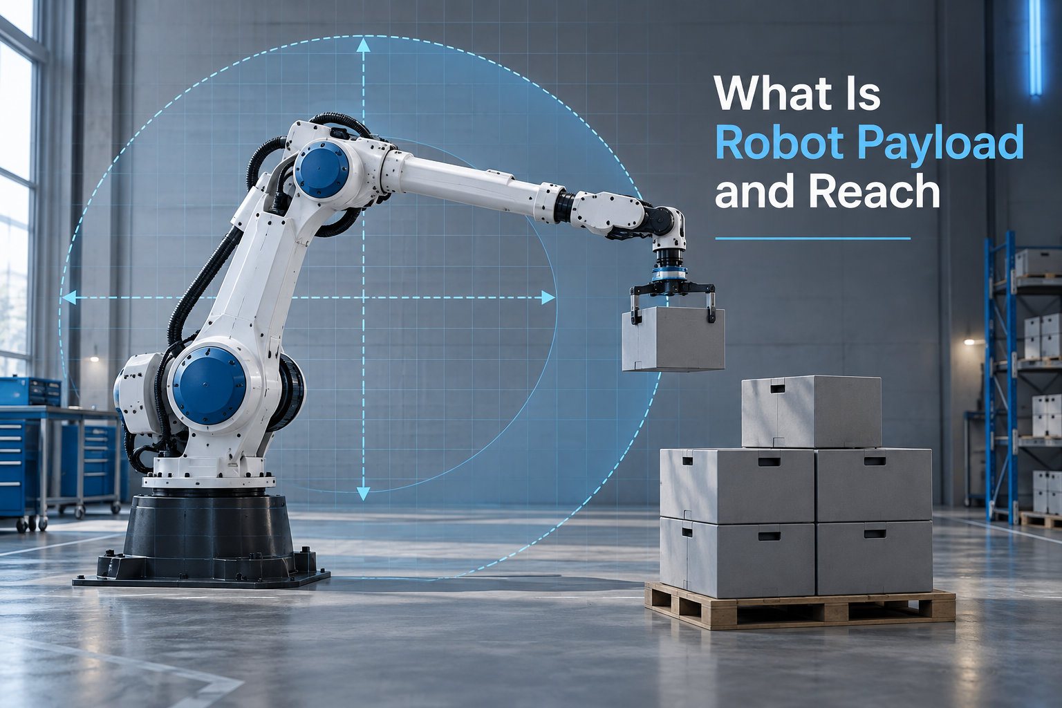
When teams start shopping for a robotic arm, two numbers on the spec sheet decide almost everything: payload and reach. Robot payload and reach together tell you what the arm can physically lift, how far it can move that load, and whether the geometry of your cell actually fits. I have watched integrators spec the wrong combination on more than one job, so let me walk you through what each term really means and how the two interact in practice.
Table of Contents
What Is Robot Payload: Definition and Explanation
Robot payload is the maximum weight a robot arm can carry and manipulate at its wrist, including the end-effector, the part being handled, and any cabling or fixtures attached to the final link. Manufacturers express it in kilograms or pounds, and the number you see on the data sheet is the rated payload — the maximum mass the robot can handle under ideal conditions.
That rated payload is measured at the J6 wrist flange, the rotating mounting plate at the very end of the arm. Everything beyond that flange counts toward your payload budget: the gripper, the welding torch, the suction cups, the camera, even the connector block. If your gripper weighs 3 kg and you want to lift a 7 kg part, you need a robot rated for at least 10 kg of payload.
Industrial robots span a huge range here. Desktop cobots like the UR5e handle 5 kg, mid-size six-axis arms such as the FANUC LR-Mate handle 7 to 30 kg, and heavy-duty models like the KUKA KR 1000 Titan lift 1,000 kg or more. Pick the right class for your load and you avoid overpaying for capacity you will never use.
What Is Robot Reach: Definition and Explanation
Robot reach is the maximum distance from the center of the robot’s base to the center of its wrist flange when the arm is fully extended. It defines the outer boundary of the volume the arm can reach, and it is typically expressed in millimeters.
Reach directly determines the size of the robot’s working envelope, also called the workspace. For a standard six-axis articulated arm, that envelope is roughly spherical, but it is not a perfect sphere — the robot cannot point straight down through the base or reach the dead zone directly behind the shoulder. SCARA robots, by contrast, have a flat, table-top workspace shaped by their two parallel joints plus a vertical stroke.
A 850 mm reach fits small benchtop cells. A 1,300 mm reach covers most machine-tending cells. Heavy-palletizing robots like the FANUC M-2000iA extend past 4,000 mm to stack loads across an entire pallet. Match the reach to the layout of your fixtures, conveyors, and machines — not just to the part weight.
Key Differences Between Payload and Reach
Payload tells you how much mass the arm can move. Reach tells you how far it can move that mass. The two are independent on the spec sheet, but they are coupled in the real world because the further the arm extends, the more leverage places on the wrist motors.
A robot rated for 20 kg of payload at full reach may only handle 10 kg when fully extended horizontally. This is called payload derating, and it is one of the most common sources of under-sized cells. Reach also drives cycle time, because a longer arm has to traverse more distance per pick.
Think of payload as the strength rating and reach as the size of the stage. A strong arm on a tiny stage can only work in a small area, while a long arm with weak wrists sags and vibrates under load. Most application problems come from optimizing one number while ignoring the other.
How Payload Is Measured and Specified
Manufacturers measure rated payload at the wrist flange with the arm in a specific test pose, usually horizontal with the elbow bent at 90 degrees and the wrist in a neutral orientation. ISO 9283 defines the test methodology for repeatability and payload, and most reputable vendors follow it.
You will see three common payload numbers on a modern data sheet:
- Rated payload — the maximum mass under standard test conditions, the headline number you compare between robots.
- Maximum payload — the absolute ceiling in reduced poses or lower speeds, often 10 to 20% above rated.
- Center of gravity offset — how far the load’s center of mass can sit from the flange face before the rating drops. This is measured in millimeters.
The moment arm of your gripper matters just as much as its mass. A 5 kg gripper hanging 150 mm from the flange imposes more wrist torque than a 5 kg gripper mounted directly to the face. Our guide to calculating a robot’s payload capacity walks through the moment-arm math in detail.
Factors Affecting Payload Capacity
Five variables determine the real payload you can run day after day. The first is motor torque at each joint, especially the wrist J4, J5, and J6 axes, which carry the full load. The second is gear ratio, where higher reduction multiplies torque but caps top speed — see our explanation of planetary gearboxes in robot joints for the mechanical side.
Third is structural rigidity of the links and castings. A flexible arm sags and oscillates under load, which hurts repeatability. Fourth is the payload derating curve, the manufacturer’s chart showing how capacity drops as the arm reaches outward or rotates the wrist.
Fifth, and often overlooked, is the inertia at the wrist. A heavy gripper does not just add mass — it adds rotational inertia when the robot accelerates and decelerates. That inertia can trip overload faults even when the static weight is well under the rating.
Payload Calculation: A Practical Guide
Follow these steps to size a robot’s payload for your application. I have used this exact checklist on dozens of integration projects and it has never undersized a cell.
- List every component attached to the wrist flange: gripper, fingers, vacuum cups, sensors, cables, fittings. Weigh each item and add them up. This is your tooling weight.
- Add the weight of the part the robot will handle, including the heaviest variant in your mix. For a gripper picking engine blocks, that is the heaviest block plus any fixture the part sits in.
- Calculate the moment arm for each component — the distance from the flange face to the component’s center of mass. Most gripper CAD models report this directly.
- Add 25 to 30% to the total as a safety margin. Robot manufacturers rate conservatively, but you still want headroom for wear, dynamic loads, and the occasional off-spec part.
- Compare your final figure to the robot’s rated payload AND to its derating chart at the worst-case working pose. If either number is tight, step up to the next payload class.
Quick example: gripper 4 kg, fingers 1 kg, part 9 kg, cabling 0.5 kg. Sum is 14.5 kg. Add 30% and you need a robot rated for at least 19 kg. A 20 kg-rated arm like the FANUC LR-Mate 200iD/7L is borderline; I would pick a 25 to 30 kg class for reliable operation.
Safety Margins: The 25-30% Rule Explained
The 25 to 30% safety margin is not a marketing trick — it is what experienced integrators use on real production lines. The margin covers four things: dynamic loads during fast moves, wear on gearboxes over the robot’s life, the off-center moment from your specific gripper geometry, and the occasional part that is heavier or wetter than spec.
On the r/robotics community, practitioners routinely warn newcomers to “size up, not down” because replacing a robot after it has been mounted is far more expensive than buying the next model up front. I agree. A $20,000 cell with an undersized robot is a 30-day delay and a $5,000 rework — far worse than paying 10% more for the right arm.
There is one exception. If your cycle time is short and your robot spends most of its time well below maximum reach, you can sometimes drop the margin to 15 to 20%. Even then, never run a robot at its published maximum — backlash, the small clearance inside the gear teeth, amplifies under heavy load, and a few thousand hours of running at the limit will eat into repeatability. For the mechanical side, see our piece on backlash in robot gearing.
Common Applications and Payload Requirements
Payload class maps fairly cleanly to application. Pick and place of small parts usually sits in the 3 to 10 kg range, perfect for SCARAs and cobots. Machine tending of small CNC mills runs 10 to 30 kg. Arc welding and sealing land in the 6 to 20 kg range, where the welding torch is a big chunk of the budget.
Palletizing is the heavyweight division. A single case of beverages weighs 12 to 25 kg, and a full layer can exceed 30 kg, so palletizing robots are typically rated for 100 to 700 kg. Material handling of large automotive body panels needs 100 to 500 kg of payload, while heavy foundry work (pouring, large casting handling) lives above 500 kg and extends into 1,000+ kg giants like the KUKA KR 1000 Titan.
Assembly tasks — pressing, screw-driving, dispensing — usually fall in the 5 to 50 kg range, depending on whether the assembly is a small PCB subassembly or a full appliance. When in doubt, I size for the worst-case part in the production mix and the heaviest gripper variant the cell might ever use.
Frequently Asked Questions
What is the payload of a robot?
The payload of a robot is the maximum weight it can carry and manipulate at its wrist flange, including the end-effector, the part being handled, and any attached cabling or fixtures. It is expressed in kilograms or pounds, and the published figure is the rated payload measured under ISO 9283 test conditions.
How to calculate robot payload?
Add the weight of every component attached to the wrist flange — gripper, fingers, sensors, cables, and the heaviest part the robot will handle. Include the moment arm of each component, then apply a 25 to 30% safety margin and compare the total to the robot’s rated payload and its derating curve at the worst-case working pose.
What is a payload example?
A 4 kg gripper handling a 9 kg engine component with 0.5 kg of cabling has a total payload requirement of 13.5 kg, which means you need a robot rated for at least 17 to 18 kg after a 25 to 30% safety margin. Real-world examples range from 1 kg payloads on desktop cobots to 1,000 kg payloads on heavy-palletizing arms.
What is the highest payload capacity industrial robot?
The highest payload capacity industrial robots today exceed 1,000 kg. Models like the KUKA KR 1000 Titan and FANUC M-2000iA/2300 are rated for 1,000 to 2,300 kg and are used in heavy-palletizing, large casting handling, and automotive body panel moving.
Conclusion
Robot payload and reach are the two specifications that decide whether a robotic arm will work in your cell, and getting them right is mostly about discipline. Add up every component on the wrist, include the moment arm, apply a 25 to 30% safety margin, and check the result against the robot’s derating curve at your worst-case pose. Match the reach to the actual layout of your fixtures and conveyors, not just to the part weight. Done carefully, the two numbers will keep your robot running reliably for years.
For a deeper look at the math behind payload capacity, the moment-arm calculation, and how to read a manufacturer’s derating chart, see our full payload calculation guide here on Smashing Robotics.