
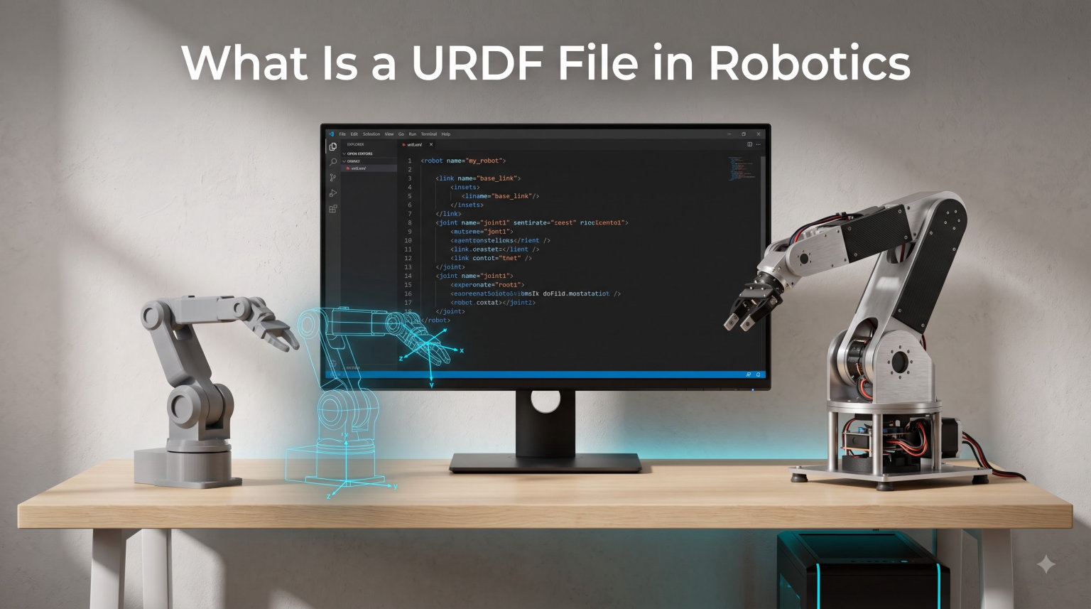
A URDF (Unified Robot Description Format) file is an XML-based file used in robotics to describe a robot’s physical structure, including its links, joints, and visual and collision properties. It provides a standardized way to represent multibody systems so that tools like ROS, Gazebo, and RViz can share and understand robot models without custom conversion.
If you have ever opened a robotics repository and seen a file ending in .urdf, you have already met this format. I have worked with URDF files on everything from six-DOF arms to mobile bases, and the same few concepts show up every time. In this guide, I will walk you through what a URDF file is, how the XML is structured, the six joint types you will use, and how to debug the most common errors. By the end, you should be able to read and write your own URDF files with confidence.
Table of Contents
What Is a URDF File in Robotics and Why It Matters
URDF stands for Unified Robot Description Format, and it was developed as part of the ROS (Robot Operating System) ecosystem to solve a simple problem: every team was inventing its own robot description format. URDF gives the robotics community one shared XML specification that any tool can parse.
At its core, a URDF file describes a robot as a tree of rigid bodies. Each rigid body is called a link, and the connections between links are called joints. Together, links and joints form a kinematic tree that defines how the robot can move, what it looks like, and how it interacts with the physical world.
URDF matters because it is the lingua franca of ROS-based robotics. When you load a robot into Gazebo for simulation, when you visualize it in RViz, when you plan motions with MoveIt, or when you run reinforcement learning in Isaac Sim, you are almost always feeding it a URDF file. Without URDF, you would need a custom importer for every tool.
The format is text-based, human-readable, and you can edit it in any text editor. That is part of the reason it has stuck around for over a decade and shows no sign of being replaced.
How URDF Files Structure a Robot
Every URDF file represents a robot as a kinematic tree, which is a hierarchical structure where one link acts as the root and every other link branches off through joints. The tree cannot contain loops, which is one of the key differences between URDF and SDF.
A link represents a single rigid body on the robot. A robotic arm might have a base link, an upper arm link, a forearm link, and a gripper link. Each link holds properties like mass, inertia tensor, visual geometry, and collision geometry.
A joint defines how two links connect and what kind of motion is allowed between them. A revolute joint lets one link rotate around an axis relative to its parent, while a fixed joint welds two links together so they move as one. The joint also carries limits like minimum and maximum angle, maximum effort, and maximum velocity.
Imagine a simple two-link pendulum. The base link is the world attachment, the upper arm is a child of the base through a revolute joint, and the bob hangs from the upper arm through another revolute joint. That is a URDF kinematic tree with two joints and three links.
This tree structure is what allows simulators and motion planners to compute forward kinematics, inverse kinematics, and dynamics. Once the tree is known, the rest of robotics math can be built on top.
URDF XML Structure Walkthrough
URDF is XML, so it follows standard XML rules. Every file starts with a robot root element that names the robot, and everything else lives inside. Here is a minimal URDF for a two-link arm:
<?xml version="1.0"?>
<robot name="two_link_arm">

  <link name="base_link">
    <visual>
      <geometry>
        <box size="0.2 0.2 0.2"/>
      </geometry>
    </visual>
    <collision>
      <geometry>
        <box size="0.2 0.2 0.2"/>
      </geometry>
    </collision>
    <inertial>
      <mass value="1.0"/>
      <inertia ixx="0.01" ixy="0" ixz="0"
               iyy="0.01" iyz="0" izz="0.01"/>
    </inertial>
  </link>

  <joint name="shoulder_joint" type="revolute">
    <parent link="base_link"/>
    <child link="upper_arm_link"/>
    <origin xyz="0 0 0.1" rpy="0 0 0"/>
    <axis xyz="0 0 1"/>
    <limit lower="-1.57" upper="1.57"
           effort="10" velocity="1.0"/>
  </joint>

  <link name="upper_arm_link">
    <visual>
      <geometry>
        <cylinder length="0.5" radius="0.05"/>
      </geometry>
    </visual>
  </link>

</robot>
Notice how the file reads almost like a description. There is a link element for each rigid body, with child tags for visual, collision, and inertial. The joint element names a joint, declares its type, and points to a parent and child link.
The origin tag inside a joint specifies where the child link sits relative to the parent, using xyz for translation in meters and rpy for roll-pitch-yaw rotation in radians. The axis tag defines the axis of rotation for revolute or continuous joints.
URDF Joint Types Explained
URDF supports six joint types, and choosing the right one is the most important modeling decision you will make. Here is a quick reference table:
Revolute joint: Rotates around an axis with a defined upper and lower angle limit. This is the standard hinge joint used for elbows, shoulders, and knees on a robot arm.
Continuous joint: Rotates around an axis with no angle limits, similar to a wheel or a spinning sensor mount. Use this when the joint can spin freely forever.
Prismatic joint: Slides along an axis with a defined distance range. Linear actuators and telescoping arms use prismatic joints.
Fixed joint: Locks two links together so they cannot move relative to each other. Fixed joints are used to attach sensors, decorative meshes, or sub-assemblies.
Floating joint: Allows all six degrees of freedom between two links. URDF supports it, but it is rarely used because it makes kinematic calculations much harder.
Planar joint: Constrains motion to a 2D plane perpendicular to an axis. Like floating, it is rare in practice and usually only appears in academic examples.
For a typical robotic arm with six or seven degrees of freedom, every active joint will be a revolute joint, and the gripper fingers might use prismatic or fixed joints depending on the design. Mobile robots usually pair continuous joints for wheels with fixed joints for the chassis and sensor mounts.
Visual vs Collision Geometry in URDF
You may have noticed in the XML example that each link can have both a visual tag and a collision tag. These serve two very different purposes, and you should treat them differently.
Visual geometry is what the user sees. It can be a high-resolution mesh loaded from a STL, DAE, or OBJ file, complete with textures and fine details. Simulators use visual geometry to render the robot on screen.
Collision geometry is what the physics engine checks against. It should be a much simpler shape, like a primitive box, cylinder, or sphere, or a low-poly convex hull. Complex meshes slow down collision detection dramatically, so the rule of thumb is to keep collision geometry as simple as possible while still resembling the real shape.
A common beginner mistake is to use the same high-poly mesh for both. I have seen projects where collision detection slowed to a crawl because the robot was using a 100,000-triangle mesh for collision checking. Switch to primitives or convex hulls and the simulation will run ten times faster.
URDF vs SDF vs Xacro
URDF is not the only robot description format you will encounter, and the differences between URDF, SDF, and Xacro come up constantly on forums. Here is a practical comparison.
URDF is the original ROS format. It is XML, it supports a kinematic tree, and it cannot describe closed loops. URDF is best for a single robot with a single instance.
SDF (Simulation Description Format) is the native format of Gazebo. It is also XML but more powerful: it supports closed kinematic loops, multiple instances of the same robot, environment description, sensors, and plugins. SDF is the right choice when you need rich simulation features.
Xacro is not a separate format but a macro language that generates URDF. It supports variables, math expressions, and reusable blocks. If you find yourself copying and pasting link definitions, switch to Xacro to clean up your files.
For most ROS 2 projects, you will write Xacro files, process them into URDF, and load the URDF into RViz, MoveIt, or Gazebo. SDF becomes necessary when you need closed chains, multiple robots, or advanced sensor simulation.
For a deeper look at how simulation infrastructure is evolving, our coverage of physical AI infrastructure platforms shaping robotics in 2026 shows where these description formats are heading.
How to Create a URDF File Step by Step
Creating a URDF file from scratch is easier than it looks. I usually follow these steps.
Step 1: Sketch the kinematic tree. Draw a simple parent-child diagram of your robot. Label each link and the joint that connects it to its parent. This becomes your structural blueprint.
Step 2: Define each link. For every link, write a link block with visual geometry, collision geometry, and an inertial block. Start with primitives like boxes and cylinders to keep things simple.
Step 3: Define each joint. For every joint, write a joint block with the right type, parent and child link, origin transform, axis, and limits. Make sure the parent link is defined before the child in the file.
Step 4: Validate the file. Use the check_urdf command from the urdfdom package to check for syntax errors and tree issues. This single command catches about 80 percent of beginner mistakes.
Step 5: Visualize the result. Open RViz and add a RobotModel display using the URDF file. You will see the robot immediately and can confirm the joint axes and link positions look correct.
If you are working with a 3D model from SolidWorks, FreeCAD, or Fusion 360, there are exporters that generate URDF automatically. The SolidWorks to URDF exporter is widely used in industry, though it requires some manual cleanup afterwards.
Common URDF Errors and How to Debug Them
Even experienced engineers hit URDF errors. These are the ones I see most often in forums and in my own projects.
Tree has multiple roots: This happens when more than one link has no parent. Every URDF must have exactly one root, typically a link named base_link. Add fixed joints to fix any orphaned links.
Joint parent does not exist: The parent link in a joint must be defined above the joint in the file. Either reorder the definitions or add the missing link.
Missing required joint attributes: Revolute and prismatic joints need an axis tag and a limit tag. Continuous joints need an axis but no limits. Fixed joints need neither.
Loop in the kinematic tree: URDF does not support closed loops. If your robot has one, you need to either break the loop with a fixed joint or switch to SDF.
Invalid inertia values: The inertia tensor must be a symmetric positive-definite matrix. Use a tool like check_urdf or urdf_to_collada to validate these numbers before running physics.
The check_urdf command should be your first debugging step every time. It outputs a summary of the tree, warns about common issues, and saves you from chasing phantom bugs in your code.
For more on how modern robotics stacks tie into URDF and other tools, see our guide on what edge AI in robotics really means.
Frequently Asked Questions
What are URDF files used for?
URDF files are used to describe a robot’s physical structure in a standardized XML format. They define the robot’s links, joints, and visual and collision properties so that ROS, Gazebo, RViz, MoveIt, and other tools can all share the same model without custom conversion. They are the standard robot description format in the ROS ecosystem.
How do I visualize a URDF file?
The easiest way to visualize a URDF file is to load it in RViz using the RobotModel display. Add the display in RViz, set the Description Topic to /robot_description, and load your URDF file into the parameter server with ros2 launch or rosparam. You can also use standalone tools like the urdf_tutorial display launch script or web-based viewers like Foxglove Studio.
How do I create a URDF file?
To create a URDF file, open any text editor and write an XML file with a robot root element. Define each link with link tags containing visual, collision, and inertial properties. Connect links using joint tags that specify the type, parent, child, origin, axis, and limits. Save the file with a .urdf extension and validate it with the check_urdf command from the urdfdom package.
What is the difference between SDF and URDF?
URDF describes a single robot as a kinematic tree and cannot handle closed loops or multiple robot instances. SDF is a more powerful XML format used by Gazebo that supports closed kinematic loops, multiple robots, environment description, sensors, and plugins. Use URDF for ROS 2 robot descriptions and SDF for full simulation scenes that need advanced features.
What is Xacro and how does it relate to URDF?
Xacro is a macro language for URDF that adds variables, math expressions, and reusable blocks. It lets you define a robot once with parameters and reuse sub-components without copy-pasting XML. You write .xacro files, then run the xacro command to generate the final .urdf file that tools like RViz and Gazebo actually load.
Wrapping Up: What a URDF File Really Means for Your Robot
A URDF file in robotics is the standard XML description of a robot’s links, joints, and geometry that every ROS tool can read. Once you understand the link-and-joint tree, the six joint types, and the difference between visual and collision geometry, you can read any URDF file and start writing your own.
Start small with a two-link arm, validate it with check_urdf, and visualize it in RViz. As your robot grows, switch to Xacro to keep the file maintainable. From there, you can move on to SDF for full simulation environments and MoveIt for motion planning. The format is simple, the tooling is mature, and once you have written a few URDF files by hand, you will never look at a robot the same way again.