
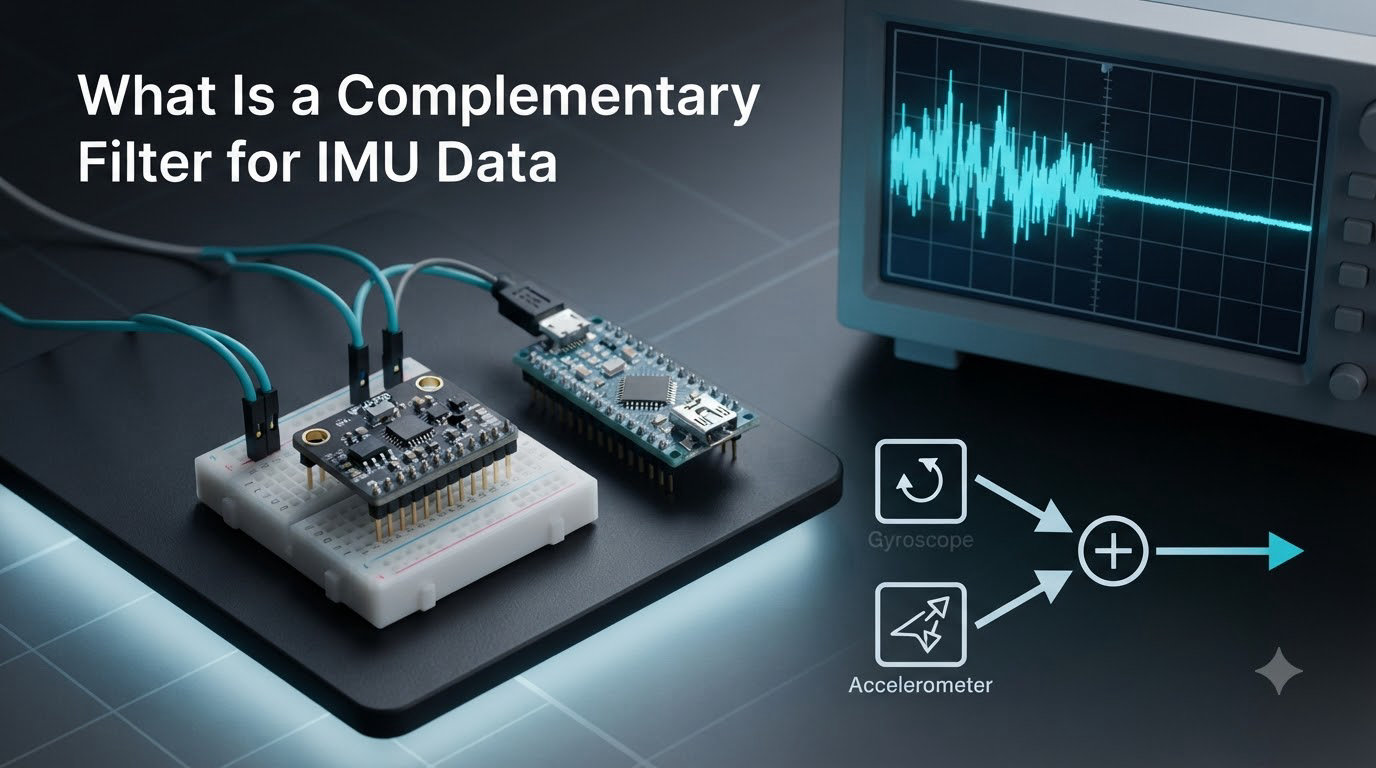
A complementary filter is a sensor fusion method that combines gyroscope and accelerometer data to estimate orientation in an IMU, using a high-pass filter on the gyro and a low-pass filter on the accelerometer to cancel out each sensor’s weaknesses. In this guide I will walk you through how it works, the actual formula, and how I have tuned it on real drones and robots in our lab.
IMUs show up everywhere in robotics, from a $5 MPU6050 on an Arduino to a tactical-grade unit in an autonomous vehicle. The challenge is that no single sensor inside the IMU tells the whole truth, so we need a way to combine them. The complementary filter is the simplest reliable way to do that, and it is the filter I reach for first when I need orientation data fast.
Table of Contents
What Is a Complementary Filter for IMU Data
A complementary filter is a lightweight sensor fusion algorithm that merges a gyroscope and an accelerometer (and sometimes a magnetometer) into a single, stable orientation estimate. The name comes from the fact that the two sensors have complementary error profiles, so combining them cancels out the worst of both.
The gyroscope measures angular velocity, so it is great at sensing quick rotations. The problem is that any tiny bias gets integrated over time and turns into a slowly growing error, called drift. The accelerometer measures the gravity vector, so it can be turned into a tilt angle directly. The problem is that it is noisy and gets upset by vibrations or any movement that adds a non-gravity acceleration.
The complementary filter is built on one simple idea: trust the gyroscope for short-term motion and the accelerometer for long-term correction. The result is an orientation estimate that is responsive in the moment and stable over time.
How a Complementary Filter Works
Under the hood, the complementary filter applies a high-pass filter to the gyroscope signal and a low-pass filter to the accelerometer signal, then adds the two filtered signals together. The two filters are designed so their frequency responses add up to 1 across the spectrum, which is why they are called “complementary.”
High-frequency content (fast rotations, vibrations) passes through the gyro path. Low-frequency content (slow drift, gravity) passes through the accelerometer path. Where one filter cuts, the other takes over, so nothing important gets lost.
The Complementary Nature of IMU Sensors
Think of the gyroscope as the short-term memory and the accelerometer as the long-term reference. On a quadcopter, the gyro reports hundreds of degrees per second during a flip, and the accelerometer is useless for that. But after the flip, the accelerometer settles and quietly reminds the system which way is down, undoing the gyro’s accumulated drift.
This is exactly the pattern users describe in robotics forums. The complementary filter works beautifully for roll and pitch on drones and balancing robots, where the accelerometer has a clear gravity reference. It also explains why yaw is harder, since gravity gives you nothing for the horizontal plane.
The Complementary Filter Formula
The standard 1D form of the complementary filter is the equation every IMU developer should recognize:
theta = alpha * (theta + gyro * dt) + (1 - alpha) * accel_angle
Where theta is the current angle estimate, gyro is the angular velocity reading in radians per second, dt is the time step in seconds, accel_angle is the angle computed from the accelerometer, and alpha is the filter gain between 0 and 1.
You can rewrite the same formula to make the two branches obvious. Let theta_gyro be the angle obtained by integrating the gyro over one step, and theta_accel be the angle derived from the accelerometer. Then the filter output is simply:
theta = alpha * theta_gyro + (1 - alpha) * theta_accel
When alpha is close to 1, the filter trusts the gyro most of the time and only leans on the accelerometer for slow correction. When alpha is close to 0, the filter behaves almost like the accelerometer alone. Most IMU implementations pick alpha in the 0.95 to 0.98 range.
Gyroscope Integration for Orientation
To get an angle from a gyroscope you have to integrate its angular velocity over time. In code that looks like angle += gyro_rate * dt, repeated every sample. This is the only step that is actually needed if your IMU is stationary or moving smoothly, but it is also the source of the drift problem.
Any bias in the gyro, even a few degrees per second of error, will integrate into ever-larger angle error the longer you run. A MEMS gyro with a 0.01 degrees per second bias will drift by roughly 36 degrees in an hour. That is why we never trust the gyroscope alone for long-duration orientation, and why the accelerometer branch of the filter exists.
Accelerometer-Based Angle Estimation
From the accelerometer you can compute pitch and roll directly using trigonometry. For example, with the gravity vector measured as (ax, ay, az) in the sensor frame, the roll and pitch angles are given by the arctan2 of the appropriate components.
The advantage of this approach is that it does not drift, since the gravity reference is absolute. The disadvantage is that the accelerometer is sensitive to any other acceleration. On a drone in flight, every propeller correction produces a brief spike that corrupts the gravity estimate. On a walking robot, foot impacts do the same thing.
That is why the filter gain is set high. The complementary filter mostly ignores the accelerometer during fast motion and only uses it once things settle, when the gravity reading is clean again.
The Filter Gain (Alpha) Parameter Explained
Alpha is the single most important tunable parameter in the complementary filter. It controls the trade-off between responsiveness and stability. A higher alpha gives a snappier, gyro-dominated response. A lower alpha gives a smoother, accelerometer-dominated response.
In practice, the choice of alpha depends on your sample rate, your sensor noise, and how much vibration your platform produces. I usually start with 0.98 for drones, 0.95 for handheld motion tracking, and 0.90 for very shaky environments. These numbers line up with what users report on robotics forums, where the 0.9 to 0.98 range is by far the most common.
Choosing the Right Alpha Value
A good rule of thumb is to set alpha proportional to your confidence in the gyroscope. If you have just calibrated the bias and the IMU is well isolated from vibration, push alpha up. If the accelerometer is noisy, or the platform experiences sudden acceleration, drop alpha a little so the filter leans more on the gravity reference during the calm moments.
Another useful trick is to make alpha adaptive. You can lower alpha temporarily when you detect high accelerometer activity and raise it back when things settle. This is essentially a poor man’s version of what the Kalman filter does, and it is enough for many applications.
Magnetometer Integration for Yaw
Yaw is the one angle the accelerometer cannot recover, because gravity has no component around the vertical axis. To estimate heading you need a third sensor, the magnetometer, which measures the Earth’s magnetic field.
On a 9-DOF IMU like the MPU9250 or BNO055, the complementary filter is extended to three axes by adding a third branch for the magnetometer. The yaw estimate becomes a fusion of the gyroscope’s integrated yaw rate and the compass heading derived from the magnetometer. The same alpha-style weighting works, and you can use a different gain for yaw if the magnetometer is particularly noisy on your platform.
Magnetometers are sensitive to hard-iron and soft-iron distortions from nearby motors and ferrous metal. On small drones I have had to mount the magnetometer on a mast well away from the power wires to get a usable heading. This is the most common reason a complementary filter yaw estimate seems wrong.
Complementary Filter vs Kalman Filter
The Kalman filter is the gold standard for IMU sensor fusion, but the complementary filter is often a better choice for simple projects. Here is how they compare on the things that actually matter when you are picking one.
The complementary filter is easier to implement, needs no matrix math, runs in a few floating-point operations per sample, and is deterministic. The Kalman filter gives better accuracy under changing conditions because it adapts its gain automatically, but it is more complex, harder to tune, and heavier on the microcontroller.
For drones, balancing robots, and most hobby projects, the complementary filter is plenty. Reach for the Kalman filter (or the more advanced Madgwick or Mahony filters) when you need maximum accuracy, or when your sensor noise and bias change a lot over time. Experts on robotics forums often point out that stacking a Kalman filter on top of a complementary filter is redundant, since the complementary filter is essentially a fixed-gain Kalman filter.
Practical Implementation: Arduino and MPU6050 Code Example
Below is a minimal Arduino sketch that fuses the MPU6050 accelerometer and gyroscope using a complementary filter. It assumes you already have raw accelerometer and gyroscope data available in your code.
// Complementary filter for roll and pitch on MPU6050
float alpha = 0.98;
float dt = 0.01;        // 100 Hz loop
float roll  = 0.0;
float pitch = 0.0;
void loop() {
  // Read accel and gyro
  float ax = readAccelX();
  float ay = readAccelY();
  float az = readAccelZ();
  float gx = readGyroX();  // in rad/s
  float gy = readGyroY();  // in rad/s
  // Tilt from accelerometer
  float accel_roll  = atan2(ay, az);
  float accel_pitch = atan2(-ax, sqrt(ay*ay + az*az));
  // Gyro integration
  roll  += gx * dt;
  pitch += gy * dt;
  // Complementary filter
  roll  = alpha * roll  + (1 - alpha) * accel_roll;
  pitch = alpha * pitch + (1 - alpha) * accel_pitch;

  delay(dt * 1000);
}
The two things to notice are the alpha weighting in the last step and the way the accelerometer-derived angles use atan2 for stability near the vertical. The filter is just a handful of operations, so it runs comfortably on an Arduino Uno at 100 Hz.
Python Example Using AHRS Library
If you prefer Python, the AHRS library on PyPI implements a quaternion-based complementary filter you can call in a few lines. After installing it with pip, you can build a filter object, feed it the raw sensor data, and read out the orientation as a quaternion or as Euler angles. This is what I reach for when I want to prototype an orientation algorithm on a Raspberry Pi before porting it to embedded C.
Brian Douglas’s YouTube tutorial on complementary filters is also a great reference if you learn better from video. The ROS imu_complementary_filter package is another trusted implementation if you work in the Robot Operating System.
Common Pitfalls and How to Avoid Them
The most common issue is vibration. Propellers, motors, and walking gaits inject non-gravity accelerations that confuse the accelerometer. Mount the IMU on vibration dampers, low-pass filter the raw accelerometer data, or use a lower alpha so the filter trusts the accelerometer less during motion.
Another pitfall is forgetting to convert units. Gyroscope data from most MEMS IMUs is in degrees per second, but the integration step and the filter math usually want radians per second. Mixing the two is a silent bug that produces a wrong-angle estimate that still looks plausible.
Finally, never skip the gyro bias calibration. A simple procedure, leave the IMU stationary for a few seconds, average the gyro readings, subtract the average from every subsequent reading, fixes most of the long-term drift before the filter even starts.
Applications: Drones, Robotics, and AHRS
The complementary filter is the workhorse of small drones. It runs at 1 kHz on the flight controller, feeds roll and pitch into the PID loops, and uses the magnetometer branch for heading. The same setup works for self-balancing robots, camera gimbals, VR headsets, and pedestrian dead reckoning.
In an Attitude and Heading Reference System (AHRS), the complementary filter is the simplest valid choice when the application does not need the precision of a full Kalman filter. For inertial navigation over long distances, where gyro drift is critical, a more advanced filter or a GPS fusion is required, but the complementary approach is usually the right starting point for orientation.
Frequently Asked Questions
What is a complementary filter?
A complementary filter is a sensor fusion method that combines gyroscope and accelerometer data to estimate orientation in an IMU. It applies a high-pass filter to the gyroscope and a low-pass filter to the accelerometer, then adds the two together so each sensor cancels the other’s error.
How does a complementary filter work for IMU data?
It works by taking a weighted sum of two orientation estimates, one from integrating the gyroscope and one computed from the accelerometer. The formula is theta = alpha * theta_gyro + (1 – alpha) * theta_accel, where alpha is the filter gain that decides how much each sensor is trusted.
Is an IMU just an accelerometer?
No, an IMU is a sensor module that typically contains a 3-axis accelerometer, a 3-axis gyroscope, and often a 3-axis magnetometer. The accelerometer is only one part of the IMU, and the complementary filter is needed precisely because the accelerometer alone gives noisy angle estimates.
Does an IMU include an accelerometer?
Yes, almost every modern IMU includes a 3-axis accelerometer as one of its core sensors, along with a 3-axis gyroscope. A 6-DOF IMU has the accelerometer and gyroscope, while a 9-DOF IMU adds a magnetometer for heading.
What is the difference between a complementary filter and a Kalman filter?
A complementary filter is a simple fixed-gain filter that runs in a few floating-point operations per sample. A Kalman filter is more accurate and adapts its gain based on sensor noise, but it is also more complex, more computationally expensive, and harder to tune. For most hobby drones and robots, the complementary filter is more than enough.
Final Thoughts on Complementary Filters for IMU Data
The complementary filter is the simplest practical way to fuse IMU data for orientation, and for most robotics projects it is all you need. Use the formula theta = alpha * theta_gyro + (1 – alpha) * theta_accel, start with alpha around 0.98, calibrate your gyroscope bias, and check that your magnetometer is free of local magnetic distortion.
If you need more accuracy or your system has changing noise conditions, graduate to the Madgwick or Mahony filters, or to a full extended Kalman filter. But for your first drone, balancing robot, or motion-tracked camera, the complementary filter is the right tool for the job.