
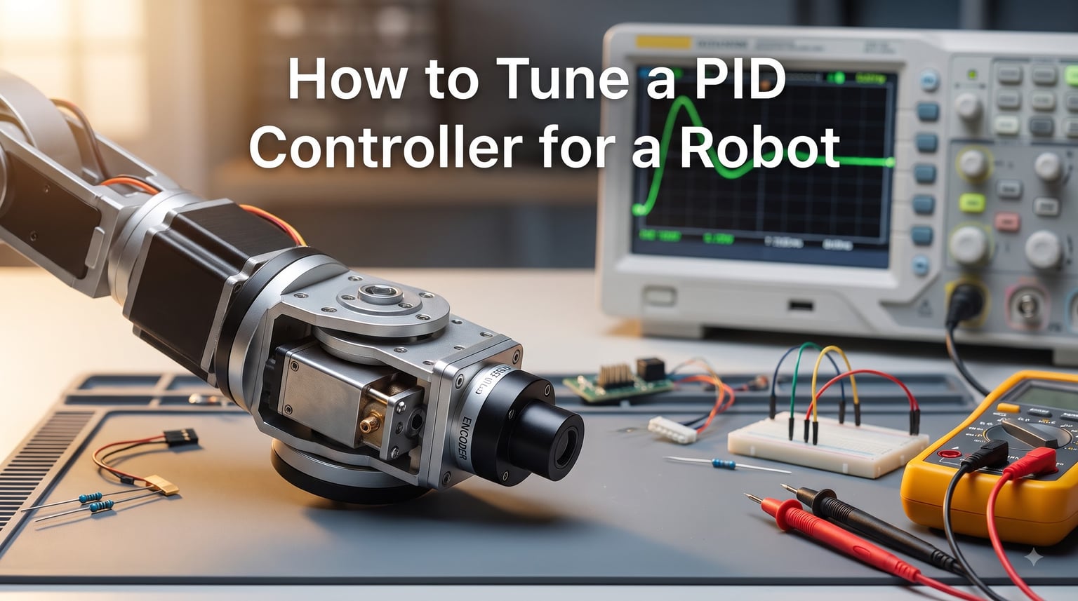
If your robot jitters, overshoots, or refuses to reach its target position, the problem usually comes down to PID controller tuning. I’ve spent years helping robotics teams and hobbyists get smooth, reliable motion from their motors, and the same handful of mistakes show up every time.
PID stands for Proportional, Integral, Derivative. It’s a feedback control algorithm that continuously adjusts motor output based on the error between where your robot is and where you want it to be. In this guide, I’ll walk you through exactly how to tune a PID controller for a robot, from your very first gain value to advanced feed-forward tricks that competition teams rely on.
You’ll see the step-by-step procedure I use, learn why Ziegler-Nichols often produces disappointing results on robots, and pick up troubleshooting tips pulled from real robotics forums. By the end, you’ll have a working tuning workflow you can apply to any motor or joint.
Table of Contents
What Is PID Control and Why It Matters for Robots
PID control is a closed-loop feedback mechanism that compares a measured value to a desired setpoint and applies a corrective output. The “PID” name comes from three mathematical terms that each handle a different aspect of the error.
Every robot with motors needs some form of feedback control. Without it, you get jerky motion, overshoot, and poor repeatability. A well-tuned PID controller is what makes a robot arm move smoothly to a target, a self-balancing robot stay upright, and a line follower track a path without wobbling.
I think of PID as the robot’s “muscle memory.” Once tuned, it reacts to disturbances automatically, no manual intervention required. If you’re building anything from a small hobby rover to a multi-axis robot arm, you’ll use PID controller tuning in some form.
The control loop runs like this: the sensor reports current position or speed, the controller computes the error, applies the PID formula, and sends a new command to the motor. This happens hundreds or thousands of times per second. Your robot chassis design and sensor quality both influence how easy the tuning process will be.
Understanding P, I, and D Components
Each of the three terms in a PID controller responds to a different characteristic of the error signal. Knowing when to use each one is the heart of effective PID controller tuning.
The Proportional Term (Kp)
Kp applies an output proportional to the current error. If your robot is far from the target, Kp produces a large response. As it gets closer, the response shrinks. Higher Kp means faster response but also more overshoot and potential oscillation.
Start with Kp alone. Most robotic systems can be controlled with just a well-tuned P term. In my experience, simple position-control loops on small motors often need nothing more.
The Integral Term (Ki)
Ki accumulates error over time and adds it to the output. This eliminates steady-state error, the small offset that remains when Kp alone can’t quite reach the setpoint, often because of gravity, friction, or a constant load.
Add Ki when your robot reaches near the target but stops short. Be careful: too much Ki causes overshoot and oscillation because past errors pile up. This is called integral windup, and it’s one of the most common complaints on robotics forums.
The Derivative Term (Kd)
Kd responds to the rate of change of error. It acts as a damper, slowing the response as the robot approaches the target. Kd reduces overshoot and improves stability.
Add Kd when your robot oscillates or overshoots even after Kp is set reasonably. The main downside: Kd amplifies sensor noise, which can cause jittery motor output. Always pair Kd with a low-pass filter on the derivative calculation.
PI vs PD vs Full PID: Choosing the Right Controller
You don’t always need all three terms. Many robotic systems work best with just two. Here’s how I decide which to use:
| Controller Type | Best For | Sign You Need It |
|---|---|---|
| P-only | Simple velocity control, soft position control | Your system has no constant load and small friction |
| PI | Position control with gravity or spring loads | Robot stops short of target under steady load |
| PD | Servo position control with low friction | Robot overshoots but doesn’t have steady-state error |
| Full PID | High-performance motion control, precision robotics | You need zero steady-state error AND no overshoot |
For most FIRST Robotics and hobby projects, a PI controller handles position control well. Reserve full PID for applications where performance is critical, like CNC machines or industrial robots.
Pre-Tuning Preparation and Safety
Before touching any gains, verify your hardware. I’ve seen teams spend hours “tuning” a system that had a loose encoder mount or a slipping gear. Fix the mechanical issues first, then tune.
Check these before you start:
- Sensor feedback is working: Read raw encoder values and confirm they match motor motion.
- Wheels or joints move freely: No binding, no excessive friction.
- Power supply is stable: Voltage drops cause control symptoms that look like tuning problems but aren’t. Read about robot brownout issues to understand what I mean.
- Motor direction is correct: Positive command should move the sensor in the positive direction.
- Code is reading the right variable: Your PID uses the correct measurement and units.
Safety warning: When first testing, elevate the robot or use a low-current limit. A badly-tuned PID can send a motor to full power instantly. Wear safety glasses and keep hands clear.
How to Tune a PID Controller for a Robot: Step-by-Step Procedure
This is the systematic procedure I use on every new robot. Follow these steps in order; don’t skip ahead. The whole process usually takes 20 to 40 minutes once you’re comfortable with it.
Step 1: Set All Gains to Zero
Initialize Kp, Ki, and Kd to zero in your code. Confirm the controller runs without crashing. Add basic telemetry so you can plot setpoint vs actual position over time.
Step 2: Increase Kp Until Oscillation
Start with Kp = 0.5 or 1.0, depending on your motor and gearing. Double the value each time until you see sustained oscillation around the setpoint. The robot should swing back and forth without settling.
For most DC motors with encoders, this critical Kp value lands between 1 and 10. If you need Kp above 50 to get oscillation, your feedback signal might be too small or scaled wrong.
Step 3: Reduce Kp by 50%
Take the Kp value where oscillation just barely starts, then cut it in half. This gives you a stable starting point. The robot should now reach the target with some overshoot but settle within a few seconds.
Step 4: Add Kd to Reduce Overshoot
Increase Kd from zero in small increments until the overshoot disappears. Watch for jittery motion; that means Kd is too high or your derivative filter is too weak. A typical Kd value is around 10-20% of Kp for position control.
Step 5: Add Ki to Eliminate Steady-State Error
Only add Ki if the robot consistently stops short of the target. Start Ki very small, often 0.01 or less. Increase slowly until the steady-state error disappears. If you see the system start oscillating again, your Ki is too high.
Step 6: Fine-Tune All Gains
With all three terms active, tweak one gain at a time in small increments. Test with different setpoints, different loads, and different starting positions. Real robot tuning is iterative.
If you’re using a ROS-based system or a microcontroller like Arduino, this same procedure applies. Just translate the gains into your code’s units. The same logic works for multi-axis robots with multiple degrees of freedom, though you’ll need to tune each joint separately.
Cascaded Control: Position, Velocity, and Current Loops
For high-performance motor control, single-loop PID isn’t enough. Industrial servo systems and modern BLDC motor controllers use a cascaded architecture with three nested loops: current (innermost), velocity (middle), and position (outermost).
Each inner loop runs faster than the one outside it. A typical setup: current loop at 8 kHz, velocity loop at 1 kHz, position loop at 100 Hz. The output of the position controller becomes the setpoint for the velocity controller, and so on.
The benefit of cascaded control: each loop handles a specific physical domain. The current loop deals with motor torque, the velocity loop deals with speed, and the position loop handles where the robot ends up. Each can be tuned independently.
The standard tuning order is current first, then velocity, then position. Tune the inner loop, lock it in, then move outward. This is how companies like Texas Instruments, Maxon, and Advanced Motion Controls build their motion platforms.
For hobby projects, you usually start with a single position or velocity loop. But once you need smooth motion under varying loads, cascaded control is the way to go.
Troubleshooting Oscillation and Instability
Here’s the most common pattern I see: a team gets oscillation, lowers Kp, now the robot is sluggish, adds Ki, oscillation returns. The cycle continues. Here’s how to break out of it.
Symptom: Continuous oscillation
- Reduce Kp immediately. You’re in the unstable region.
- Add Kd if not already present. Derivative action damps oscillations.
- Check your loop time. PID loops that run too slowly act like they’re adding delay.
Symptom: Slow oscillation with growing amplitude
- Your Ki is too high. The integral term is accumulating faster than it can discharge.
- Add anti-windup protection by clamping the integral sum.
Symptom: Jittery motor at rest
- Kd is amplifying sensor noise. Add a low-pass filter on the derivative path.
- Check your encoder resolution. Too few counts per revolution creates quantization jitter.
Symptom: Robot never reaches setpoint
- You’re missing Ki. P-only control can’t overcome constant loads.
- Check for actuator saturation. If your motor is at max output and still not moving, no amount of PID will help until the load is reduced.
One more thing: mechanical problems often masquerade as tuning issues. A loose belt, a bent shaft, or a friction binding will look like bad gains. Always verify the mechanics first. We’ve covered this in detail in our guide on robot power systems, since voltage issues can also create these symptoms.
Feed-Forward Control: VFF and AFF for Better Performance
Feed-forward is a powerful addition to PID that uses knowledge of the desired motion to pre-emptively apply motor output. Instead of waiting for error to develop, feed-forward calculates what output should be needed and adds it directly.
Two common feed-forward terms:
Velocity Feed-Forward (VFF): Adds a constant output proportional to desired velocity. This is what overcomes friction and back-EMF at a given speed. Without VFF, your PID controller has to use Kp to constantly “push” against friction, which causes tracking error.
Acceleration Feed-Forward (AFF): Adds output proportional to desired acceleration. This overcomes the inertia of the robot arm or load. AFF is what makes the robot arm track a complex trajectory without lag.
Feed-forward terms don’t affect stability the way feedback gains do. You can add them aggressively without causing oscillation. They dramatically improve tracking performance, especially for motion profiles with smooth velocity ramps.
For competition robotics, I’ve seen feed-forward terms cut position error by half or more on the same hardware. If your robot needs to follow precise trajectories, feed-forward is essential.
Why Ziegler-Nichols Often Fails for Robotics
The Ziegler-Nichols method is the most famous PID tuning technique, developed in the 1940s. It works by finding the “ultimate gain” that causes sustained oscillation, then applying formulas to calculate Kp, Ki, and Kd.
For robotics, this method has real problems. It produces aggressive gains designed for quarter-amplitude damping, which means about 25% overshoot. That’s far too much for most motion control applications where you want precise, non-overshooting positioning.
Ziegler-Nichols also assumes a simple process response that doesn’t match most robotic systems. Geared motors have nonlinear friction, varying inertia, and saturation effects that the method ignores.
My recommendation: use Ziegler-Nichols as a starting point, then manually tune down. It gets you in the right ballpark, but the final values will need adjustment. For a self-balancing robot or a motor with low friction, the manual step-by-step procedure I described earlier works better.
Common PID Tuning Mistakes to Avoid
I’ve collected the most common mistakes from Reddit’s r/robotics, control forums, and years of helping teams. Avoid these and you’ll tune faster.
Mistake 1: Tuning without sensor verification. Always confirm your encoder or sensor reports the correct values before tuning. A misaligned sensor creates a control system that fights itself.
Mistake 2: Changing multiple gains at once. Only adjust one gain at a time so you can see the effect. Otherwise, you can’t tell which change helped or hurt.
Mistake 3: Ignoring loop timing. If your PID loop runs at 50 Hz but should run at 200 Hz, gains will behave unexpectedly. Match the loop rate to your hardware capability.
Mistake 4: Forgetting to account for gravity. A robot arm holding a horizontal position needs more output than one at vertical. Either add gravity compensation in your feed-forward or accept that Ki must handle it.
Mistake 5: Tuning one setpoint, expecting all to work. Test multiple setpoints, especially small and large ones. PID behavior can change dramatically with setpoint size due to motor nonlinearity.
Mistake 6: Not testing under load. A PID that works with no payload will often fail when you add a gripper or tool. Test with the actual working load.
Mistake 7: Skipping anti-windup. Without anti-windup protection, integral windup causes huge overshoots after large setpoint changes. Always clamp the integral term.
Testing and Validating Your Tuning
Once your PID is tuned, don’t trust it until you’ve tested it. Here’s my validation checklist:
- Step response test: Command a sudden setpoint change and record the response. Look for low overshoot, fast settling time, no oscillation.
- Disturbance rejection: Push the robot or load while it’s holding position. It should recover quickly.
- Different setpoints: Test small, medium, and large setpoint changes. Performance should be consistent.
- Different loads: Add your actual payload and retest. Tuning often needs adjustment under load.
- Long-duration test: Run for several minutes to check for thermal effects and drift.
Good PID tuning feels smooth. The motor reaches its target without drama, holds steady under load, and recovers quickly from disturbances. If your graphs show large overshoot, persistent oscillation, or slow settling, keep tuning.
One area teams often overlook: power supply quality. Your tuning can be perfect on the bench but fail in the field if the battery voltage sags under load. Check that your system delivers stable voltage during high-current operations.
Frequently Asked Questions
What Kp value should I start with when tuning a robot PID?
Start with Kp = 1.0 for most motor and encoder systems. Double it each test cycle until you see sustained oscillation. The critical Kp that causes oscillation is your starting reference. Cut that value in half for a stable working point, then adjust from there.
Should I use Ziegler-Nichols method for robotics?
Ziegler-Nichols can work as a starting point, but it typically produces aggressive gains with 25% or more overshoot, which is too much for most robotic applications. We recommend using it to find ballpark values, then manually tune down for smoother performance.
When should I add derivative (Kd) to my PID controller?
Add Kd when your robot overshoots the target or oscillates after setpoint changes. Derivative action damps the response and reduces overshoot. The main downside is that Kd amplifies sensor noise, so always pair it with a low-pass filter on the derivative calculation.
What are VFF and AFF feed-forward terms?
VFF (velocity feed-forward) adds a constant output proportional to desired velocity, overcoming friction and back-EMF. AFF (acceleration feed-forward) adds output proportional to desired acceleration, overcoming inertia. Both terms improve tracking performance without affecting stability, which is why they’re standard in high-performance robotics.
My robot oscillates after setpoint changes – is this normal?
Some initial oscillation is common while tuning, but sustained oscillation is not normal and indicates your gains are too high. Reduce Kp immediately, add Kd if not present, and check for integral windup. If oscillation persists, lower Ki to zero and start with P-only control again.
How do I prevent integral windup?
Prevent integral windup by clamping the integral sum to a maximum value, using anti-windup logic that pauses integration when the output is saturated, or using a back-calculation method. Also, command smaller setpoint changes, and use motion profiles instead of instant jumps to targets.
Conclusion
PID controller tuning for robots is a skill you’ll build with practice. The systematic procedure I outlined (set all gains to zero, increase Kp until oscillation, reduce by 50%, add Kd, then Ki if needed) works for most robotic systems. Once you have the basics down, add feed-forward terms for smoother motion and explore cascaded control for high-performance applications.
Remember that PID tuning is iterative. Your first set of gains won’t be perfect, and that’s fine. Test, observe, adjust, and repeat. With time, you’ll develop intuition for how each gain affects your robot’s behavior. For more on building robust robots, explore our guides on robot power wiring and related topics.