
A PID controller is the workhorse of modern robotics. I have used PID loops to stabilize quadcopters, control robotic arm joints, and regulate motor speeds on autonomous vehicles. If you work with any system that needs precise control, understanding PID is essential.
In this complete guide, I will break down what a PID controller is, how the three components work together, and how you can implement one in your own robotics projects. Whether you are building a self-balancing robot, tuning a drone flight controller, or controlling a robotic gripper, the principles here will give you a solid foundation. If you are new to robotics control concepts, you may also want to read our guide to multi-axis robot control and degrees of freedom before diving in.
Table of Contents
What Is a PID Controller?
A PID controller (Proportional-Integral-Derivative controller) is a feedback control mechanism that continuously calculates an error value as the difference between a desired setpoint and a measured process variable. It then applies a correction based on three mathematical terms to minimize that error over time.
Think of it this way: when you set a thermostat to 72 degrees, the PID controller measures the current temperature, calculates how far off it is from your target, and adjusts the heating or cooling output to bring the room to that temperature. It does this calculation thousands of times per second, learning from past errors and anticipating future ones.
Here is the short definition for featured snippets: A PID controller is a feedback control system that uses three terms (proportional, integral, and derivative) to continuously adjust a process output and minimize the error between a desired setpoint and the actual measured value.
You will find PID controllers in nearly every industry. They regulate temperature in ovens, control speed in electric motors, stabilize drones in mid-air, and keep robotic arms moving with millimeter precision. The reason they are so popular comes down to simplicity and reliability. A well-tuned PID controller can handle most control tasks without requiring complex mathematics or expensive hardware.
How Does a PID Controller Work?
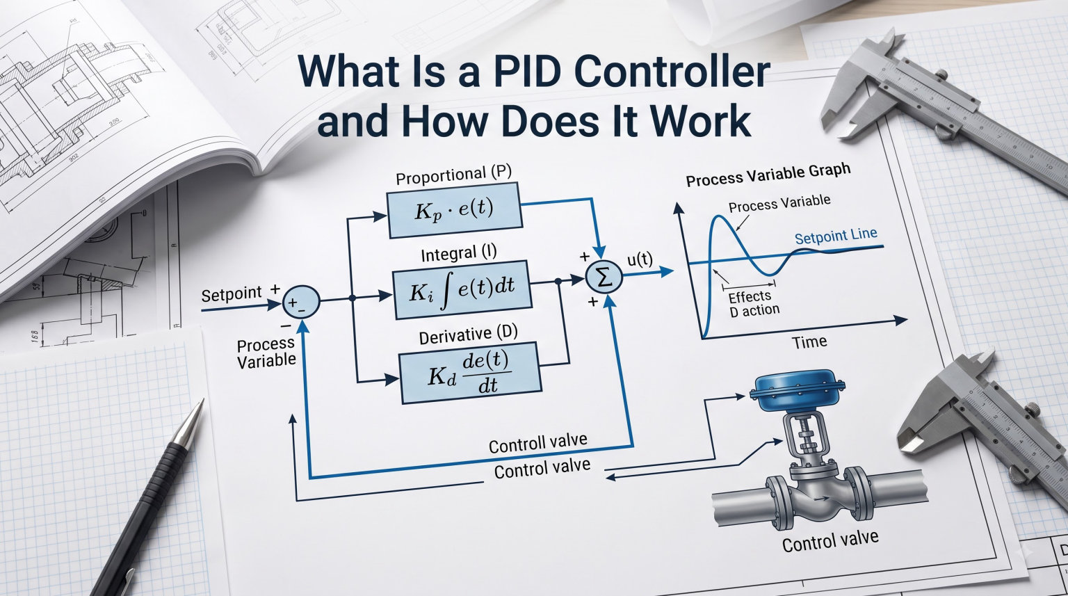
A PID controller works by creating a closed feedback loop between the system being controlled and the controller itself. Here is how the process flows in plain English:
- The controller receives a setpoint (the target value you want to achieve, like 100 RPM motor speed).
- A sensor measures the current process variable (the actual motor speed right now).
- The controller calculates the error by subtracting the process variable from the setpoint.
- The PID algorithm processes this error through three mathematical terms.
- The controller outputs a corrective signal to an actuator (like a motor driver).
- The actuator adjusts the physical system, and the cycle repeats, typically every 1 to 100 milliseconds.
This continuous loop is what makes PID a closed-loop control system. Unlike open-loop control (where you just send a command and hope for the best), PID constantly measures results and adjusts accordingly. If a robot arm gets bumped or a drone encounters wind, the PID controller compensates automatically.
For a robotics example, imagine controlling a servo motor to move a robotic arm to a specific angle. You command 90 degrees, but the arm is currently at 45 degrees. The PID controller sees a 45-degree error, calculates the right motor voltage to reduce that error, and keeps adjusting until the arm settles at exactly 90 degrees. For more on how robotic positioning works, see our breakdown of robotic motion control and kinematics.
The Three Components of a PID Controller Explained
The “PID” in PID controller stands for Proportional, Integral, and Derivative. Each term handles a different aspect of the error correction. Understanding what each one does is the key to tuning a controller effectively.
Proportional (P) Control
The proportional term responds to the current error. It multiplies the error by a constant called Kp (proportional gain) and outputs that as part of the control signal.
The formula is simple: P output = Kp × error. If your error is large, the proportional response is large. If the error is small, the response is small. This makes intuitive sense: bigger mistake, bigger correction.
Here is a robotics example. If a drone is tilted 30 degrees off level, you need a strong motor correction. If it is only 2 degrees off, a gentle nudge will do. The proportional term provides exactly that scaling.
The catch: proportional control alone cannot always eliminate the error completely. The system may settle at a value slightly off from the setpoint, called steady-state error. Increasing Kp speeds up the response but can also cause oscillation if pushed too high.
Integral (I) Control
The integral term looks at the history of errors. It accumulates past errors over time and multiplies that sum by a constant called Ki (integral gain).
The purpose is to eliminate steady-state error. If your drone consistently hovers 1 meter below its target altitude, the integral term will keep adding up that small error until the controller output is strong enough to close the gap.
Think of it like filling a bathtub. The proportional term reacts to how far the water level is from the target. The integral term keeps track of how long the water has been below the desired level, eventually applying enough pressure to reach it.
The downside: too much integral action causes overshoot and oscillation. The accumulated error can push the system past the setpoint before it settles. This is called integral windup, and it is one of the most common problems PID users face.
Derivative (D) Control
The derivative term predicts future errors by looking at how fast the error is changing. It multiplies the rate of change by a constant called Kd (derivative gain).
The derivative term acts like a brake. If the error is shrinking quickly, the derivative term reduces the controller output to prevent overshooting. If the error is growing quickly, it boosts the output to react faster.
Imagine driving toward a wall. The proportional term is your gas pedal (based on distance). The derivative term is your brake pedal, applying harder braking as you get closer faster. Together, they help you stop precisely at the wall without crashing into it.
The major drawback: derivative action amplifies sensor noise. Small fluctuations in sensor readings cause large derivative outputs. This is why many practical implementations either skip the D term or filter it heavily.
How P, I, and D Work Together
When combined, the three terms create a control response that is fast, accurate, and stable. The proportional term handles immediate correction, the integral term eliminates long-term error, and the derivative term dampens oscillations and prevents overshoot. The final PID output is simply P + I + D.
The PID Controller Formula and Math
The standard PID equation looks like this:
Output(t) = Kp × e(t) + Ki × integral of e(t)dt + Kd × de(t)/dt
Here is what each symbol means:
- Output(t): The control signal sent to the actuator at time t.
- e(t): The error at time t (setpoint minus measured value).
- Kp: Proportional gain constant.
- Ki: Integral gain constant.
- Kd: Derivative gain constant.
- integral of e(t)dt: The integral (sum) of all past errors.
- de(t)/dt: The derivative (rate of change) of the current error.
In a digital system (like an Arduino or microcontroller), this equation is computed at discrete time steps. Instead of a continuous integral, you sum the errors from previous iterations. Instead of a true derivative, you calculate the difference between the current error and the previous error.
The discrete form simplifies to: Output = Kp × error + Ki × (sum of errors) + Kd × (error – previous error).
For robotics applications, this discrete form is what you actually code. Most robotics libraries like ROS (Robot Operating System) include built-in PID controllers that handle these calculations for you.
How PID Controllers Are Used in Robotics
PID controllers are everywhere in robotics. From simple hobby projects to advanced industrial automation, they handle the precise control tasks that make robots work reliably. Here are the three most common robotics applications.
Motor Speed and Position Control
Controlling motor speed is the classic PID use case. You set a target RPM, a sensor (like an encoder) measures actual RPM, and the PID controller adjusts voltage to the motor until speed matches.
For position control, the same principle applies but with angle as the target. A robotic arm joint uses an encoder or potentiometer to report its current angle. The PID controller drives a servo or stepper motor until the joint reaches the commanded position. You can read more about end-effector control in our guide to precise end-effector positioning.
Industrial robotic arms typically have 6 or more PID controllers, one per joint. Each joint needs its own set of tuned Kp, Ki, and Kd values based on its mechanical characteristics.
Drone Flight Stabilization
Quadcopters are inherently unstable. Without constant correction, they would flip over within a second of takeoff. PID controllers running thousands of times per second keep them level in the air.
A flight controller uses IMU (Inertial Measurement Unit) data to detect orientation errors. Three PID loops manage roll, pitch, and yaw. When the drone tilts 5 degrees forward, the PID increases rear motor speed and decreases front motor speed to level it out.
Self-balancing robots use the same idea with two wheels. The PID controller constantly adjusts wheel speed based on tilt angle from an IMU. This is one of the most popular beginner robotics projects, and it is essentially a PID tuning exercise.
Robotic Arm Joint Control
Each joint in a robotic arm is an independent control problem. A shoulder joint carrying a heavy payload needs different tuning than a wrist joint moving a lightweight gripper. PID controllers handle this elegantly by running separate control loops per joint.
For gripper control, PID manages grip force and position. Too little force and the object slips. Too much force and you crush delicate items. A well-tuned PID controller finds the sweet spot. Check out our guide on end-effector control systems and robotic grippers for more detail.
PID vs Other Control Methods
PID is not the only control strategy available. Depending on your application, alternatives may work better. Here is how PID compares to other common methods.
PID vs On/Off Control: On/Off control (like a home thermostat) simply switches output fully on or off. It is cheap and simple but causes constant cycling around the setpoint. PID provides smooth, proportional control without the constant on-off chatter.
PID vs Fuzzy Logic: Fuzzy logic uses rule-based reasoning (if error is large AND increasing, then output is high). It handles nonlinear systems well and does not require a mathematical model. PID works best on linear systems with predictable behavior.
PID vs Neural Network Control: Neural networks learn control behavior from data. They excel at complex, nonlinear systems like walking robots or autonomous driving. However, they require training data and significant computational resources. PID is faster, simpler, and works well for most standard control tasks.
For most robotics applications, especially hobby and mid-range industrial projects, PID remains the best balance of simplicity, performance, and reliability. You only need to consider alternatives when dealing with highly nonlinear dynamics or when you have abundant training data and compute power.
How to Tune a PID Controller
Tuning means finding the right values for Kp, Ki, and Kd. A poorly tuned controller oscillates, overshoots, or responds too slowly. Here are two practical methods that work for most robotics applications.
Manual Tuning Process
The manual approach is what most hobbyists and engineers use. It is iterative but gives you a feel for how each parameter affects performance.
- Start with P only. Set Ki and Kd to zero. Increase Kp until the system oscillates, then back it off by about 50%.
- Add I to eliminate steady-state error. Slowly increase Ki until the system reaches the setpoint without major overshoot. Too much Ki causes oscillation and slow settling.
- Add D to reduce overshoot. Increase Kd until the system settles quickly without oscillating. Be careful, as too much D amplifies sensor noise.
- Fine-tune all three. Make small adjustments to each parameter until you get fast response, minimal overshoot, and zero steady-state error.
A practical tip from our own robotics builds: start with very small values and work up. Doubling a gain each step is too aggressive. Try multiplying by 1.5 and watch the response. Patience beats speed when tuning PID.
Ziegler-Nichols Method
The Ziegler-Nichols method is a systematic tuning approach developed in the 1940s. It still works today and is widely taught in control engineering courses.
- Find the ultimate gain (Ku). With Ki and Kd set to zero, increase Kp until the system oscillates at a constant amplitude. Record this Kp value as Ku.
- Measure the oscillation period (Tu). Time one full oscillation cycle. This is your Tu value.
- Apply the tuning formulas. For a classic PID controller: Kp = 0.6 × Ku, Ki = 2 × Kp / Tu, Kd = Kp × Tu / 8.
Ziegler-Nichols gives you a starting point, not a final answer. The result often has some overshoot, so you will likely need to reduce Kp by 10-20% after applying the formulas.
For more advanced tuning, software tools like MATLAB, Python’s python-control library, or even online PID simulators can automate the process using methods like Cohen-Coon or IMC (Internal Model Control).
Common PID Problems and Troubleshooting
Even well-designed PID systems run into issues. Here are the most common problems and how to fix them.
Oscillation: The system keeps overshooting and undershooting the setpoint in a repeating pattern. This usually means Kp is too high or Ki is too high. Reduce the proportional gain first, then the integral gain.
Overshoot: The system passes the setpoint before settling back. Increase Kd to add more damping, or reduce Kp to slow the response.
Slow response: The system takes too long to reach the setpoint. Increase Kp for a faster reaction, or increase Ki if there is persistent steady-state error.
Steady-state error: The system settles at a value slightly off from the setpoint. Increase Ki to accumulate more correction over time.
Integral windup: The integral term keeps accumulating error even when the actuator is saturated (at its maximum output). This causes massive overshoot once the system finally responds. Fix it by clamping the integral sum to a maximum value, a technique called anti-windup.
Noise amplification: The derivative term amplifies sensor noise, causing jittery output. Filter the input signal with a low-pass filter, or reduce Kd. Many implementations omit the D term entirely for this reason.
For robotics projects involving gear-driven joints, mechanical backlash can also cause hunting behavior. Read our article on robot joint mechanics and planetary gearboxes to understand how backlash affects PID performance.
Implementing PID in Arduino and Robotics Projects
If you want to try PID for yourself, Arduino makes it easy. Here is a simplified implementation for motor speed control using an encoder.
First, define your PID variables and the discrete formula. Set a target RPM (setpoint), read the actual RPM from your encoder (process variable), and compute the error. Then apply the PID formula and output the result to your motor driver via PWM.
A basic Arduino PID loop runs inside a timer interrupt at a fixed frequency (typically 50-200 Hz for motor control). Reading the encoder, computing the PID, and updating PWM output all happen within that interval. Most robotics platforms like ROS have ready-made PID packages (ros_controllers) that handle the timing and tuning for you.
For drone flight controllers, PX4 and ArduPilot use cascaded PID loops. An outer loop manages position, while an inner loop controls attitude. Each loop has its own PID gains tuned for its specific response time.
When implementing PID, pay attention to your loop timing. Inconsistent timing causes erratic behavior. Use hardware timers or a real-time operating system to ensure your PID runs at a consistent frequency.
PID Controller Limitations and When Not to Use One
Despite their versatility, PID controllers have real limitations. They work best on linear systems with predictable dynamics. Highly nonlinear systems (like a flexible robot arm that bends under load) need adaptive control or model-predictive control instead.
PID also requires tuning. A poorly tuned controller can be worse than no controller at all, causing instability or damage. Systems with significant time delays (deadtime) are particularly tricky for PID.
If your system has multiple interacting inputs and outputs (MIMO), or if dynamics change significantly during operation (like a robot arm picking up objects of different weights), consider adaptive PID or a more advanced control strategy.
For most hobby robotics and standard industrial applications, though, PID is more than capable. The simplicity, low computational cost, and decades of proven performance make it the first choice for control engineers worldwide.
Frequently Asked Questions
What does PID stand for in a PID controller?
PID stands for Proportional, Integral, and Derivative. These are the three mathematical terms the controller uses to calculate its output. The proportional term responds to current error, the integral term accumulates past errors, and the derivative term predicts future errors based on the rate of change.
Can you explain what a PID controller is in simple terms?
A PID controller is like a smart thermostat that constantly measures how far off a system is from its target and adjusts the controls to fix it. It uses three strategies at once: reacting to how wrong it is now (proportional), remembering how wrong it has been over time (integral), and anticipating where it is heading (derivative).
How does PID work for dummies?
Imagine you are driving a car and trying to maintain exactly 60 mph. If you are going 50, you press the gas harder. If you have been driving too slow for a while, you press it even harder to make up for lost time. If you are approaching 60 mph quickly, you ease off the gas to avoid speeding. That is PID in action: immediate response, accumulated correction, and predictive braking.
Is PID control difficult to learn?
The basic concept is not difficult at all, and most beginners can understand how PID works within a few hours. Mastering PID tuning takes more practice, since you need to develop intuition for how Kp, Ki, and Kd affect system behavior. Hands-on projects like a line-following robot or a self-balancing robot are great ways to build that intuition.
What are the disadvantages of a PID controller?
PID controllers struggle with highly nonlinear systems, have difficulty handling significant time delays, and require manual tuning for optimal performance. The derivative term amplifies sensor noise, and the integral term can cause windup if not properly managed. For complex systems with multiple interacting variables, more advanced control strategies may be necessary.
What is Kp, Ki, and Kd in a PID controller?
Kp is the proportional gain, which determines how strongly the controller reacts to current error. Ki is the integral gain, which controls how much past errors influence the output. Kd is the derivative gain, which determines how much the controller reacts to the rate of error change. Tuning these three values is what makes a PID controller work well.
How do you tune a PID controller?
Start by setting Ki and Kd to zero and increasing Kp until the system oscillates. Then back off Kp by about 50%. Next, slowly increase Ki to eliminate any remaining steady-state error. Finally, add small amounts of Kd to reduce overshoot and oscillation. Make small adjustments and test after each change. The Ziegler-Nichols method provides a systematic starting point for tuning.
How is PID used in robotics?
PID controllers in robotics manage motor speed and position, stabilize drones, control robotic arm joints, regulate gripper force, and handle balance control in mobile robots. Nearly every precision movement in robotics relies on PID loops running at high frequency to maintain accuracy.
Conclusion
A PID controller is one of the most important tools in robotics and automation. It provides reliable, precise control across countless applications, from simple motor speed regulation to complex multi-axis robot arms. The three components, proportional, integral, and derivative, work together to handle immediate correction, long-term accuracy, and predictive damping.
Now that you understand what a PID controller is and how it works, the best way to deepen your knowledge is hands-on practice. Build a line-following robot, tune a self-balancing platform, or stabilize a small quadcopter. Each project will teach you something new about how Kp, Ki, and Kd shape system behavior.
Looking ahead, PID is evolving. Modern implementations combine PID with adaptive algorithms, fuzzy logic, and even neural networks to handle increasingly complex systems. Self-tuning PID controllers can adjust their own gains based on real-time performance, and AI-assisted tuning is making manual guesswork less common. Still, the fundamental PID principles you learned here will remain relevant for decades to come.
If you want to keep learning about robotics control systems, explore our guides on robot power and control systems and the differences between forward and inverse kinematics. These topics build directly on the control foundation PID provides.