
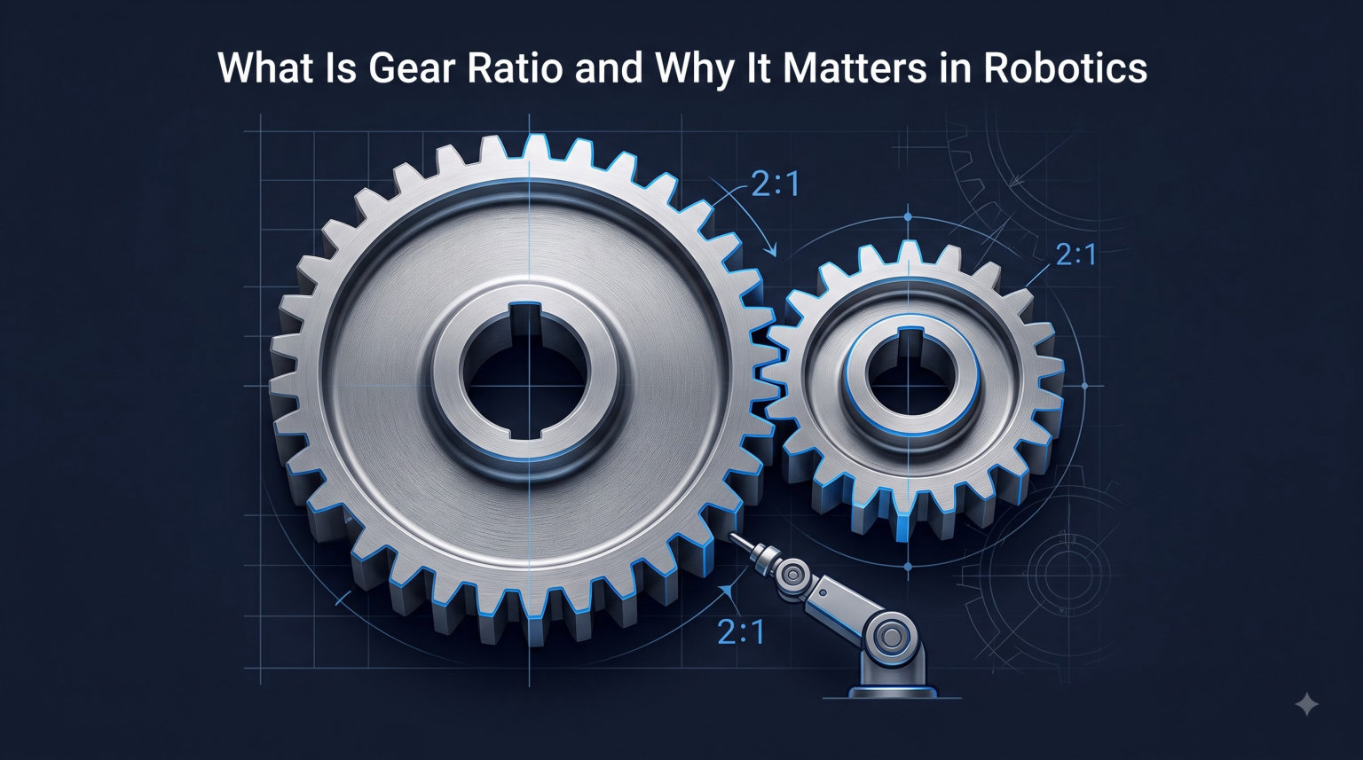
Gear ratio is the ratio of the number of teeth on the driven gear to the number of teeth on the driver gear, and it dictates how rotational speed and torque are exchanged between a motor and a robot joint. In simple terms, gear ratio robotics decides whether your robot moves fast or moves strong, and most designs need a careful balance of both. In this guide I will walk you through the formula, the physics, the gear types that show up in real robots, and the design decisions that make or break a robotic system.
By the end you will understand how to calculate any gear ratio, why a 100:1 reduction is common in humanoid robots but causes real problems, and how collaborative robot designers use gravity to choose between high and low ratios.
Table of Contents
What Is Gear Ratio in Robotics?
A gear ratio in robotics is the relationship between the rotational speeds and torques of two meshed gears, expressed as the ratio of teeth on the driven gear to teeth on the driver gear. The driver gear is the one connected to the motor shaft (the input), and the driven gear is the one delivering power to the output shaft (the load).
When two gears mesh, each tooth on the driver gear must engage exactly one tooth on the driven gear. If the driver has 10 teeth and the driven has 30 teeth, the driven gear must rotate three times slower than the driver. The math is simple: Gear Ratio = Teeth on Driven Gear / Teeth on Driver Gear.
This matters in robotics because most motors spin too fast and produce too little torque to drive a robot joint directly. A typical DC motor might run at 10000 RPM and produce 0.05 Nm of torque, which is useless for lifting a 1 kg arm. Adding a gearbox with a 100:1 ratio converts that motor into something that delivers 5 Nm at 100 RPM, which is far more useful for a robot joint.
Gear reduction is the term used when the output speed is lower than the input speed, which is the most common configuration in robotics. Gear multiplication is the opposite, where the output spins faster than the input, though this is rarely useful in robot joints because it amplifies speed at the cost of usable torque.
Key Terminology You Should Know
The input gear is the smaller pinion gear connected to the motor. The output gear drives the load. Reduction ratio means the input must turn multiple times to produce one output rotation. A 10:1 ratio means the motor must rotate 10 times for the output shaft to complete one full rotation.
Backlash is the small gap between meshing teeth that causes a tiny amount of slop when reversing direction. It matters in precision robotics, where even fractions of a degree of lost motion can ruin accuracy at the end effector.
Service factor is a multiplier you apply to the calculated torque to account for shock loads, start-stop cycles, and real-world variability. A service factor of 1.5 is common for smooth-running robots, while 2.0 or higher is used for heavy industrial applications with frequent direction changes.
How to Calculate Gear Ratio
You calculate gear ratio by dividing the number of teeth on the driven gear by the number of teeth on the driver gear, or by dividing the input RPM by the output RPM. Both methods give the same answer, and I will show you both below.
The standard formula is: Gear Ratio = Driven Teeth / Driver Teeth. For example, a pinion with 12 teeth driving a gear with 60 teeth gives 60 / 12 = 5:1. This means the input shaft must rotate 5 times for the output shaft to rotate once.
The RPM formula is: Gear Ratio = Input RPM / Output RPM. If your motor spins at 6000 RPM and you measure 200 RPM at the output, the ratio is 6000 / 200 = 30:1. Both formulas describe the same physical relationship.
Step-by-Step Calculation Example
Let me walk through a real example I use when designing small robot arms. Say you have a 12V DC motor rated at 8000 RPM under no load, and you need an output speed of 200 RPM to drive a gripper joint. The required ratio is 8000 / 200 = 40:1.
To achieve 40:1, you can use a pinion with 10 teeth and a gear with 400 teeth, but that single-stage gear is impractically large. Instead, you split the reduction into two stages: a 5:1 first stage and an 8:1 second stage. The compound ratio is 5 x 8 = 40:1, which is what you need.
The output torque at the gripper joint is motor torque times ratio times efficiency. If the motor produces 0.2 Nm, and the gearbox is 80 percent efficient, the output torque is 0.2 x 40 x 0.8 = 6.4 Nm. That is more than enough to close a typical gripper with a 1 kg payload.
Working With Multi-Stage Gear Trains
Multi-stage gear trains multiply the ratios of each stage to get the total reduction. A planetary gearbox with three stages can deliver ratios from 30:1 up to 1000:1 in a compact package. Calculating the final RPM is straightforward: Output RPM = Input RPM / (Stage 1 Ratio x Stage 2 Ratio x Stage 3 Ratio).
For a 3-stage planetary gearbox with ratios of 5:1, 5:1, and 4:1, the total ratio is 5 x 5 x 4 = 100:1. With a 6000 RPM input, the output is 6000 / 100 = 60 RPM. This is how industrial robot arms achieve precise slow, strong motion from compact motors.
One thing to watch in multi-stage designs is cumulative efficiency. Four stages at 95 percent efficiency each give 0.95^4 = 0.815 total efficiency, or 81.5 percent. Five stages drop to 77 percent. This is why very high ratios in a single stage (like harmonic drives) are valuable for overall efficiency.
The Torque Multiplication Rule
Torque at the output equals torque at the input multiplied by the gear ratio, minus efficiency losses. A motor producing 1 Nm through a 50:1 gearbox ideally delivers 50 Nm at the output. In practice you lose 10-30 percent to friction, so you actually get 35-45 Nm.
The formula is: Output Torque = Input Torque x Gear Ratio x Efficiency. A 100:1 harmonic drive with 80 percent efficiency delivers 80 Nm of output torque from 1 Nm of input torque. This is why high-ratio gearboxes are essential for lifting heavy robot payloads.
Stall torque is the maximum torque a motor can produce at zero RPM, and it is the upper limit you should not exceed in your calculations. Most DC motors have a stall torque roughly 5 to 10 times their continuous rated torque, and exceeding this for too long causes permanent damage.
The Speed vs. Torque Trade-Off
The speed vs torque trade-off in gear ratio robotics is an inverse relationship: as torque increases, speed decreases proportionally, and power is conserved minus efficiency losses. You cannot get more of both from a gearbox, and choosing the right balance is the central design decision in any robot.
This trade-off exists because power equals torque times angular velocity. If a 100 W motor produces 0.1 Nm at 10000 RPM, the same power through a 100:1 gearbox produces 10 Nm at 100 RPM. The product is the same (within efficiency losses), but the application determines which form you need.
Power Conservation in Practice
Power conservation means the gearbox cannot create energy out of nothing. The energy going in equals the energy coming out, minus heat losses from friction. A poorly designed gear train with 60 percent efficiency throws 40 percent of the input power away as heat, which quickly leads to motor overheating and premature failure.
Common forum reports from FTC and FRC teams confirm this: choosing gear ratios that are too high for the motor stall torque causes the motor to overheat within seconds of stalling. The right ratio keeps the motor in its efficient operating range.
Always check the continuous torque rating of the motor, not the peak or stall torque. Continuous torque is the maximum torque the motor can produce indefinitely without overheating. Designing around continuous torque gives you a robot that runs reliably for hours instead of minutes.
When to Choose High Ratio vs. Low Ratio
High gear ratios (above 50:1) deliver high torque and low speed, which is ideal for lifting heavy loads precisely. Low gear ratios (below 20:1) deliver high speed and low torque, which is ideal for fast pick-and-place operations or chassis drive systems.
For competition robots, the team at Chief Delphi found that 16:1 is the lowest practical gear ratio for a chassis drive, with 18:1 offering a good balance between speed and control. Below 16:1, the motors spin too fast for the gear teeth to stay meshed reliably under impact loads.
For humanoid robots, the industry standard is around 100:1 ratio per joint, which gives enough torque to support the robot’s weight but creates a backdrivability problem. When an external force pushes the robot, the gears cannot easily be pushed back, so the robot has no sense of where its joints actually are. This is a proprioception issue that high-end humanoids solve with exotic torque sensors.
Types of Gear Systems Used in Robotics
The most common gear systems in robotics are spur gears for simple applications, planetary gears for compact high-ratio reductions, harmonic drives for precision, and cycloidal drives for high-torque compact designs. Each gear type has trade-offs in size, weight, efficiency, backlash, and backdrivability.
Choosing the right gear type for your robotics project is just as important as choosing the right ratio. A 100:1 strain wave gearbox behaves very differently from a 100:1 planetary gearbox, and the wrong choice can make your robot inaccurate or slow.
Spur Gears
Spur gears are the simplest and cheapest gear type, with straight teeth mounted on parallel shafts. They are easy to manufacture and have good efficiency above 90 percent per stage, but they produce noise and have limited ratios per stage (typically up to 10:1).
Spur gears are common in hobby robotics, educational kits, and low-cost mechanisms. They are not ideal for high-precision robotic arms because the straight-cut teeth create noticeable backlash, which makes accurate positioning difficult.
Planetary Gear Systems
Planetary gears use a central sun gear, multiple planet gears, and an outer ring gear to deliver high ratios in a compact package. They are the workhorse of industrial robotics, with ratios from 3:1 up to 1000:1 across multi-stage designs.
A planetary gearbox is backdrivable at low ratios (under 30:1) but becomes non-backdrivable at high ratios. This is why collaborative robots using planetary gears often have extra torque sensors to detect collisions, since the gears themselves cannot transmit reaction forces back to the motor.
Common planetary gearbox suppliers for robotics include Maxon, Faulhaber, and Harmonic Drive Systems, with ratios commonly available in 4:1, 5:1, 10:1, 20:1, 50:1, and 100:1 steps.
Harmonic Drive (Strain Wave Gearing)
Harmonic drives, also called strain wave gears, deliver extremely high ratios (30:1 to 320:1) in a single stage with near-zero backlash. They use a flexible spline, a circular spline, and a wave generator to achieve reduction. They are the gold standard for precision robotics, including robot arms in surgical, space, and semiconductor applications.
Harmonic drives have low efficiency (around 70-80 percent) due to the elastic deformation of the flexspline, but they offer unmatched precision. Most high-end 6-axis robot arms use harmonic drives in the wrist joints where repeatability matters most.
The flexspline is a thin, flexible cup with external teeth that deforms slightly as the wave generator rotates. This deformation is what creates the high ratio, but it also limits the lifetime of the drive under high cyclic loads. Most harmonic drives are rated for 10000 to 20000 hours of operation.
Cycloidal Drives
Cycloidal drives use eccentric cam followers and a ring of pins to achieve high ratios (30:1 to 100:1) in a compact package. They are more shock-tolerant than planetary gears and offer excellent torque density, which is why they appear in heavy-payload industrial robots and humanoid joint modules.
Community reports from r/robotics confirm that cycloidal drives are practical for robotics at 100:1 ratios in compact sizes, making them a popular alternative to harmonic drives when cost is a concern. The trade-off is slightly higher friction and slightly more wear over time.
Sumitomo and Nabtesco are the dominant suppliers of cycloidal and precision reducers for industrial robotics, and they appear in many famous humanoid robot designs, including the actuators used in some of the most advanced bipedal robots.
Quick Comparison of Gear Types
- Spur gears: Simple, cheap, high efficiency, high backlash, low ratio per stage.
- Planetary gears: Compact, high ratio, good efficiency, moderate backlash, becomes non-backdrivable at high ratios.
- Harmonic drives: Ultra-high ratio in one stage, near-zero backlash, low efficiency, expensive.
- Cycloidal drives: High ratio, shock-tolerant, compact, good torque density, moderate cost.
Why Gear Ratio Matters in Robotics
Gear ratio matters in robotics because it determines whether a motor can actually move the load, how precisely the robot can position itself, and whether the robot can sense forces from the outside world. A robot with the wrong gear ratio either stalls, overshoots, crashes, or fails to detect collisions.
For humanoid robots, 6-axis arms, SCARA robots, and collaborative robots, gear ratio is the single biggest design decision after motor selection. Get it wrong and the robot is unusable.
Motor-to-Load Matching
The job of the gear ratio is to match the motor’s speed-torque curve to the load’s speed-torque requirements. A motor that produces 0.1 Nm at 10000 RPM is useless for a 5 Nm load at 100 RPM, but a 100:1 gearbox makes the same motor perfect for the job.
This matching is where most beginners go wrong. They pick a motor they like, then try to find a gearbox that matches, when the better workflow is to calculate the required joint torque first, then work backward to the motor and gear combination.
Collaborative Robots and Backdrivability
Collaborative robots (cobots) work alongside humans, which means they must be able to detect collisions and stop safely. Backdrivability means an external force can push the gears backward, which lets the motor sense the force and react.
A high gear ratio (above 50:1) is non-backdrivable, meaning once the robot is powered off, you cannot push the joints manually. This is fine for a heavy industrial robot but dangerous for a cobot that needs to be repositioned by hand during teaching.
Modern cobots use low gear ratios (around 10:1 to 30:1) combined with torque sensors on every joint. This makes the robot backdrivable, lets the operator push it into position, and lets the sensors detect any unexpected force for instant safety stops.
Gravity as a Design Constraint
Gravity is the silent design constraint in robot arms. Any horizontal arm holding a weight needs sufficient torque at the shoulder joint to counteract gravity, and the gear ratio determines how much torque you can deliver at that joint.
For a 6-axis robot arm holding a 5 kg payload, the shoulder joint might need 50 Nm of torque. A motor producing 0.5 Nm on its own requires a 100:1 gearbox to deliver 50 Nm, which is why industrial robots use very high ratios at the shoulder.
For a 7-axis cobot designed to work alongside humans, the designer might choose a lower ratio with a torque sensor to detect gravity-induced forces. This trade-off is at the heart of cobot design philosophy.
Source Robotics makes a strong case that gravity should be the starting point for any robot arm design. The torque required to hold a payload against gravity sets the floor for the gear ratio, and backdrivability sets the ceiling for how high you can go.
Backlash and Precision
Backlash is the small angular gap between gear teeth that causes lost motion when reversing direction. For a precision robot arm aiming for 0.1 mm accuracy, backlash must be below 0.05 degrees per joint.
Harmonic drives have near-zero backlash and are the gold standard for precision. Planetary gears have moderate backlash (0.1 to 0.5 degrees). Spur gears have the highest backlash (often above 1 degree) and are not suitable for precision positioning.
Common Mistakes When Choosing Gear Ratio
The most common mistake is oversizing gear ratio. Higher ratio sounds safer, but it costs efficiency, increases backlash, and makes the robot non-backdrivable. Pick the lowest ratio that meets your torque requirement, not the highest you can afford.
The second common mistake is ignoring efficiency at high ratios. A 100:1 planetary gearbox is only 80 percent efficient, while a 100:1 harmonic drive is also only 80 percent efficient. That 20 percent loss shows up as heat in the motor and reduced battery life in mobile robots.
The third common mistake is forgetting about IP ratings and sealing. Gearboxes that operate in dusty or wet environments need sealing, and seals add friction that reduces efficiency. A robot working in a clean room can use unsealed gearboxes for maximum efficiency.
Future Trends in Gear Ratio Design
The newest trend in robotics is the integrated joint module, which combines a brushless motor, a high-ratio cycloidal or harmonic gearbox, a torque sensor, and a controller into a single compact unit. These modules are appearing in modern humanoid robots and exoskeletons where space and weight are critical.
Direct-drive motors are also making a comeback in collaborative robots and smaller arms. Direct-drive means no gearbox at all, which gives full backdrivability and zero backlash but requires very large, expensive motors to deliver the same torque. Tesla’s Optimus humanoid uses a mix of high-ratio and low-ratio joints depending on the duty cycle of each joint.
Frequently Asked Questions
What is the gear ratio in robotics?
The gear ratio in robotics is the ratio of the number of teeth on the driven gear to the number of teeth on the driver gear, which controls how rotational speed and torque are exchanged between a motor and a robot joint. A ratio above 1:1 means the output is slower but stronger than the input, which is the most common configuration for robot joints.
Why is the gear ratio important?
Gear ratio is important because it determines whether a motor can actually move the robot’s load, how precisely the robot can position itself, and whether the robot can safely detect external forces. Without the right ratio, the motor either stalls, overshoots, or fails to respond to collisions.
Why are gears important in robotics?
Gears are important in robotics because they convert the fast, weak rotation of small motors into the slow, strong rotation that robot joints need. They also enable speed control, torque multiplication, and precision positioning, which are all essential for any working robot arm, mobile robot, or humanoid.
What is gear ratio in simple words?
Gear ratio is how many times the driving gear must spin to make the driven gear spin once. A 5:1 gear ratio means the motor spins 5 times for every 1 rotation of the output, and the output has 5 times more torque than the input.
How do I choose gear ratio for a robot arm?
To choose gear ratio for a robot arm, calculate the required torque at each joint based on the payload weight and arm length, then divide that by the motor’s rated torque. Add a safety factor of 1.5 to 2, and choose the nearest standard ratio from a planetary or harmonic drive that delivers that reduction.
Conclusion
Gear ratio robotics is the foundation of how motors actually do useful work in robots. The ratio decides how speed and torque are traded, which gear type makes sense, and whether the robot can be precise, backdrivable, and safe.
If you are building your first robot, start with the calculation method: find the torque you need at each joint, then divide by your motor’s torque to get the required ratio. Choose a planetary gearbox for general use, a harmonic drive for precision, and a cycloidal drive for high-torque compact joints. Avoid going above 100:1 in a single stage unless you need extreme precision or torque density.
For 2026 and beyond, the same principles still apply, but the tools keep getting better. Servo motors with integrated gearboxes, smart torque sensors, and modular cobot gear systems are making it easier than ever to design robots with the right gear ratio from day one.