
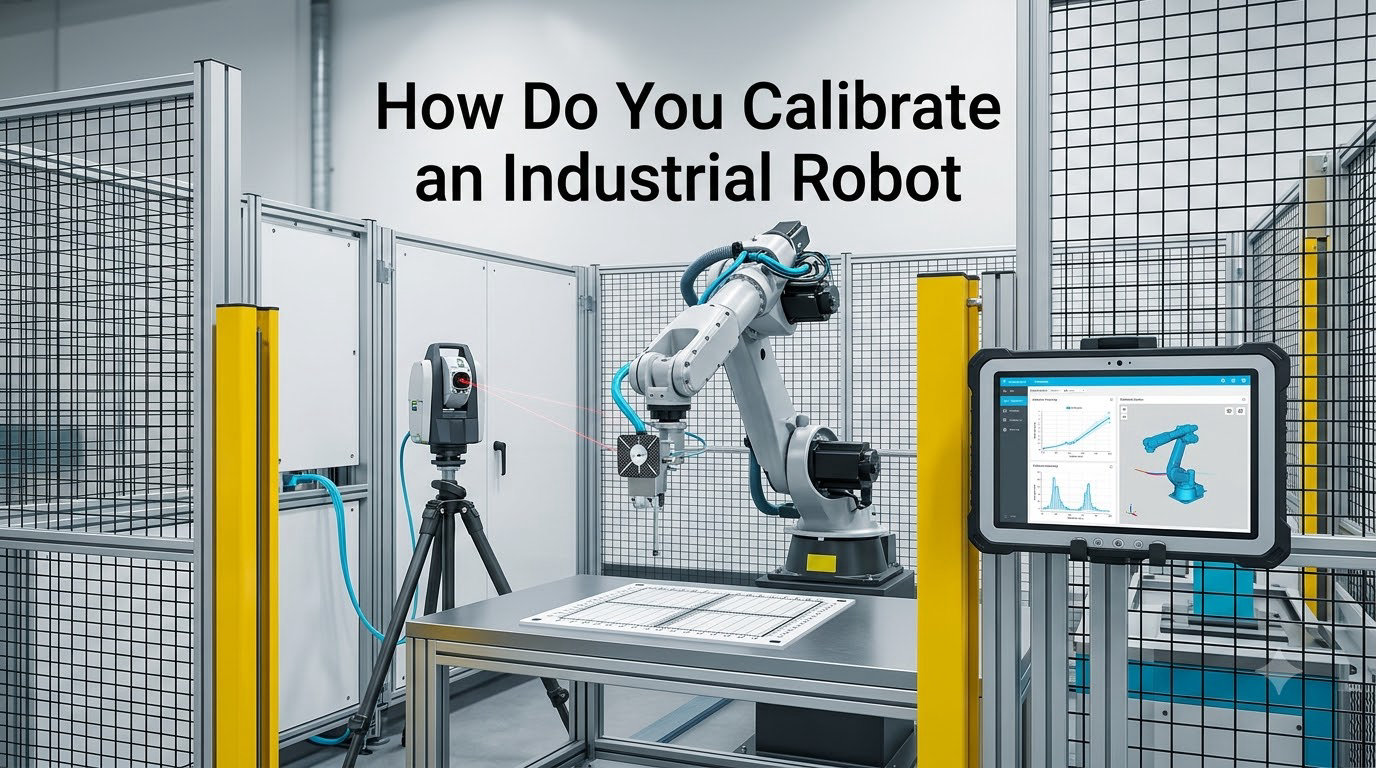
If you have ever watched a six-axis arm drift half a millimeter off a welding seam, you have seen the exact problem that calibration exists to solve. Learning how to calibrate an industrial robot is the difference between a machine that merely repeats its mistakes and one that hits true positions, cycle after cycle, for years at a time.
In this guide I will walk you through the entire process the way our team explains it on the shop floor. We will start with the definition, then unpack the difference between accuracy and repeatability, and finally run through the step-by-step procedure our engineers use on Fanuc, ABB, and Universal Robots cells. By the end you will know what tools you need, how long it takes, and when to bring in a professional.
Table of Contents
What Is Industrial Robot Calibration
Robot calibration is the process of identifying and correcting certain parameters in the kinematic structure of an industrial robot, such as the relative position of robot links and joint offsets, to improve its absolute positioning accuracy.
The goal is not to make a robot move more smoothly. Modern arms are already smooth. The goal is to make the reported position match the actual position in the real world, so that offline programs, machined paths, and inspection routines line up with the hardware. According to the ISO 9283 standard, calibration targets pose accuracy and pose repeatability across a defined workspace, not just a single teach point.
Most modern controllers store nominal kinematic values from the factory. Those values are good enough for pick-and-place work where the robot is taught every point. They are not good enough for offline programming, robot machining, or high-precision assembly, where small errors compound across the full range of motion.
Why Calibration Matters: Accuracy vs Repeatability
Accuracy is the ability of a robot to move to a commanded position in the absolute coordinate system. Repeatability is the ability of a robot to return to a position it has already been taught.
This distinction trips up almost everyone the first time. An out-of-the-box industrial robot is typically repeatable to about plus or minus 0.02 mm but only accurate to between 1 mm and 10 mm depending on payload, reach, and pose. That is a 50x gap. Repeatability is a controller property. Accuracy is a physics problem, and physics has to be measured.
Why does the gap exist? Because the manufacturer’s nominal model assumes perfect link lengths, perfect joint alignment, and zero deflection under load. None of that is true. Gears have backlash. Links flex. Encoders have a tiny index error. Each small error adds up at the tool tip.
Calibration closes that gap. With a proper kinematic calibration run, our team has consistently seen accuracy improvements of a factor of 5 to 10 on standard six-axis arms. For robot machining and metrology, that improvement is the difference between scrap and saleable parts.
The Three Levels of Robot Calibration
Robot calibration is generally divided into three nested levels, and knowing which one you need saves both time and money.
Level 1, the joint level, calibrates the absolute position of each joint encoder relative to a hard home mark. This is sometimes called mastering, and most manufacturers expect you to do it at install and after major maintenance.
Level 2 calibrates the world level, meaning the relationship between the robot base, the workpiece, and any external axes. Cell calibration at this level lets offline programs match the real cell within a few tenths of a millimeter.
Level 3 calibrates the tool level, including the tool center point, the tool orientation, and any payload-induced deflection. This is what most people call TCP calibration, and it is the level that gets done most often in production.
For most production cells, Levels 1 and 3 cover the bulk of real-world need. Level 2 is essential for offline programming and is mandatory for any robot that cuts, dispenses, or inspects with tight tolerances.
Tools and Measurement Systems You Need
The right measurement system depends on the accuracy you need and the budget you have. There is no single best answer.
A laser tracker is the gold standard for kinematic calibration. Systems from API, Leica, and FARO measure 3D points to within a few microns at ranges up to 80 meters. A tracker rental plus a day of engineer time typically lands in the mid four figures. It is overkill for a pick-and-place cell, but essential for aerospace or machining cells.
A portable measuring arm, such as a Romer or a Nikon Metrology arm, gives you 6 degrees of freedom at the tool tip and is more affordable for small cells. Accuracy is in the 0.05 mm to 0.1 mm range.
Camera-based systems, including stereo vision and photogrammetry, are fast and flexible. They are popular for eye-to-hand and eye-in-hand calibration of cameras mounted on the robot. They trade absolute accuracy for speed.
The lowest-cost option is a fixed-point fixture: a precisely machined pin or nest that the tool touches in multiple orientations. With careful work and a four or five-point touch-up, you can hit about 0.5 mm TCP accuracy for free. This is the method most used by hobbyists and small shops.
Step-by-Step Calibration Process
Here is the calibration procedure we use on a typical six-axis industrial robot. Allow about 20 to 60 minutes of cell time for Levels 1 and 3, and an extra hour if you are doing a full Level 2 kinematic run.
Step 1: Master the Robot Joints
Move each axis to its mechanical home mark using the controller’s mastering routine. On Fanuc this is called mastering, on ABB it is called calibration, and on Universal Robots it is called encoder offset setup. Follow the manufacturer procedure exactly. Skipping this step is the single most common reason calibration results look bad.
Step 2: Define the Base and Tool Frames
Set the user frame, the world coordinate system the robot uses for Cartesian moves, by touching three or four points on a known reference fixture. Set the tool frame next, defining the position and orientation of the tool center point relative to the robot flange. Without these two frames, every measurement in the next step is meaningless.
Step 3: Measure Pose Data
Drive the robot to 30 to 50 distinct poses spread across the working envelope. At each pose, record the joint angles reported by the controller and the Cartesian position measured by your external device. Good pose selection is critical. Stack the poses near singularities and you will get a poorly conditioned optimization. Spread them out and you will get a robust kinematic model.
Step 4: Run Kinematic Optimization
Feed the measured data into a calibration package. RoboDK, the Cognibotics package, and the commercial offerings from Renishaw all use a least-squares or quasi-Newton optimization to identify corrected DH parameters and joint offsets. The result is a set of updated kinematic constants that you load back into the controller.
Step 5: Validate and Verify
Measure 10 to 20 new poses that were not in the training set and compare the reported position to the measured position. For most production cells you should see sub-millimeter agreement across the workspace. For a high-precision cell, push for under 0.2 mm. If the verification fails, check for backlash, payload errors, and thermal drift before re-running the optimization.
Tool Center Point Calibration Explained
Tool center point, or TCP, calibration defines the position of the working tip of your end effector relative to the robot mounting flange. It is the most common calibration task in any robot cell, and most operators can run it without specialist support.
The classic four-point method is fast and good enough for most tasks. Touch a fixed reference point with the tool in four distinct orientations, rotating the wrist between touches. The controller solves for the TCP automatically. Expect accuracy around 0.5 mm.
For higher accuracy, use a laser tracker or a probe to record 30 or more touches in different orientations, then fit the TCP using a least-squares routine. This is what our team does for machining and dispensing cells, and it routinely delivers TCP repeatability below 0.05 mm.
For robots carrying a vision camera, you can also calibrate the camera-to-robot transform using a calibration target with known fiducials. This is called hand-eye calibration and is essential for vision-guided pick-and-place and inspection systems.
When Should You Recalibrate a Robot
There is no universal calendar, but there are clear triggers that should put calibration on the schedule.
Recalibrate after any collision, no matter how minor. Even a small impact can shift a reducer or stretch a coupling, and a 0.1 mm shift in a single joint will show up as several millimeters of error at the tool tip.
Recalibrate after any major mechanical service, including motor replacement, reducer swap, or belt change. Recalibrate when you change a significant payload, especially if you add or remove 20 percent or more of the rated load.
Recalibrate when the cell has moved or the workpiece fixture has been reworked. And recalibrate at least once a year as part of preventive maintenance, even if nothing has changed. Thermal cycling, vibration, and long-term wear will slowly erode accuracy over months of operation.
Common Calibration Errors and Troubleshooting
When a calibration result looks wrong, the problem is almost always one of a handful of usual suspects.
The most common error is a loose or shifted base frame. If the robot is bolted to a flexible table or a poorly supported frame, the base can move slightly between teach and run, and your calibration numbers will look noisy. Anchor the robot to a heavy, rigid plate and re-run.
The second most common error is using the wrong tool payload data. If the controller thinks the tool weighs 2 kg but the actual tool is 8 kg, the arm will sag differently than the model predicts. Always update the payload data before calibration.
The third common error is thermal drift. A robot that has been running for an hour is warmer than a cold robot, and that changes link lengths and joint gaps. Let the robot warm up for 30 minutes before you measure, and keep the cell temperature stable during calibration.
Finally, watch for singularities. Calibration poses taken too close to a wrist singularity will produce wildly inconsistent measurements and will pollute the optimization. A quick rule: keep the wrist joint at least 30 degrees away from its zero line in every measurement pose.
Cost of Robot Calibration in 2026
Budgets vary widely, and there is no single right number, but here is what our team sees in the field.
A DIY TCP calibration using a fixed pin costs nothing beyond the time of the operator, and that work is part of normal setup. A full kinematic calibration done in-house with a rented laser tracker typically runs between 2,000 and 6,000 dollars for a day of work, including equipment and labor.
Bringing in a specialist for an annual calibration visit on a single robot usually lands between 3,500 and 8,000 dollars depending on the cell. For a multi-robot line, the per-robot cost drops because the engineer and equipment are already on site.
The expensive option is the production-stopping accuracy problem you could have caught with a routine calibration. For most cells, treating calibration as preventive maintenance rather than an emergency is the cheaper path.
Frequently Asked Questions
How do you calibrate an industrial robot?
You start by mastering the joint encoders against their home marks, then you define the base frame and tool frame using a fixed reference. Next, you measure 30 to 50 robot poses with an external device such as a laser tracker, run a least-squares optimization on the kinematic parameters, and load the updated values back into the controller. Finally, you verify the result on a fresh set of poses to confirm sub-millimeter agreement.
How accurate is robot calibration?
A proper kinematic calibration typically improves absolute positioning accuracy by a factor of 5 to 10 compared to factory nominal values. Standard six-axis arms often move from 1 to 10 mm of factory accuracy down to 0.1 to 0.3 mm after calibration, depending on the robot size, payload, and the measurement system used.
How much does it cost to calibrate an industrial robot?
A basic TCP and frame calibration done in-house is essentially free apart from operator time. A full kinematic calibration with a rented laser tracker typically costs between 2,000 and 6,000 dollars. Bringing in a specialist for a single-robot annual visit usually lands between 3,500 and 8,000 dollars.
What are the steps for robot calibration?
The five main steps are: master the robot joints, define the base and tool frames, measure 30 to 50 poses with an external measurement system, run a kinematic optimization to identify corrected parameters, and verify the result on independent poses. Allow 20 to 60 minutes for Levels 1 and 3, and an extra hour for a full Level 2 run.
How often should you calibrate an industrial robot?
Calibrate at least once a year as preventive maintenance, and immediately after any collision, motor or reducer replacement, payload change of more than 20 percent, or significant rework of the cell fixture. For high-precision cells, run a verification every six months.
What is the difference between accuracy and repeatability?
Repeatability is how closely a robot returns to a position it has already been taught, and modern industrial robots are repeatable to about 0.02 mm. Accuracy is how closely the robot hits a commanded position in the absolute world coordinate system, and factory accuracy is usually 1 to 10 mm. Calibration is the process of closing the gap between the two.
Conclusion
Calibrating an industrial robot is part maintenance, part measurement science, and part discipline. If you remember nothing else, remember this: master the joints, define your frames, measure with a good system, optimize with a proven package, and verify on fresh data.
Set a calendar reminder for an annual check, and pull the trigger any time a collision, a payload change, or a fixture rework breaks the routine. That is the path to keeping your cell within tolerance and your scrap rate near zero.