
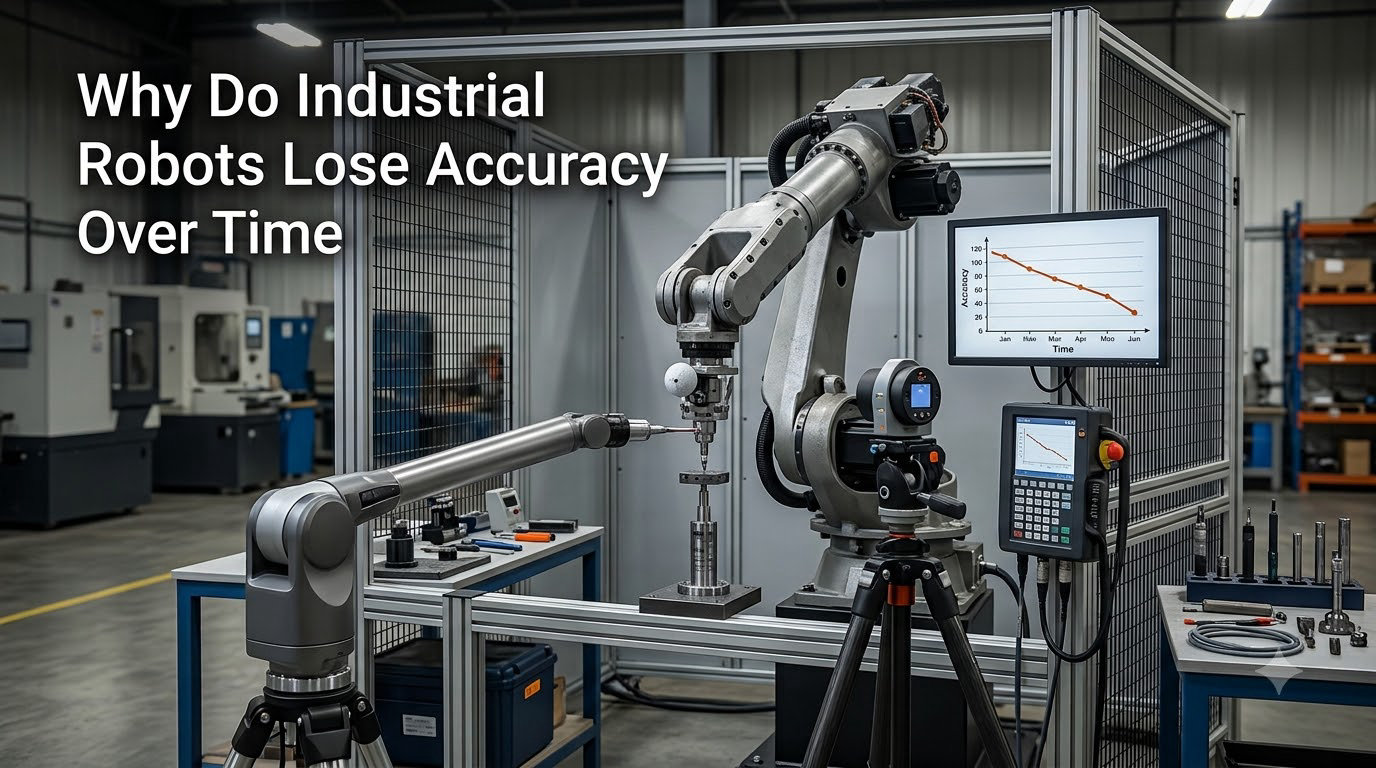
I’ve spent years around robotic welding cells and CNC tending stations, and one question keeps coming up from plant managers: why do industrial robots lose accuracy over time? The short answer is that every robot leaves the factory as a precise but inaccurate machine, and the gap between commanded position and actual position only widens as components age. In this guide, I’ll walk you through the mechanical, thermal, and software factors behind that drift, show you the warning signs our team looks for, and share the maintenance practices that actually preserve accuracy in real production environments.
By the end, you’ll know exactly which parts of your robot fail first, how often to recalibrate, and what to do before a 0.1 mm error becomes a pile of scrapped parts.
Table of Contents
What Is Robot Accuracy and How Does It Differ From Repeatability
Positioning accuracy measures how closely a robot’s actual end-effector position matches the position you commanded in your program. Repeatability (often called precision) measures how consistently the robot returns to the same taught point when you run the same motion hundreds of times in a row.
Here’s the part that confuses most operators I work with: a standard industrial robot can have repeatability of plus or minus 0.02 mm while still being off by 1 mm or more from the commanded location. The robot repeats its own mistake with incredible consistency. That’s why out-of-the-box robots are precise but inaccurate, and why absolute positioning accuracy is a separate specification from repeatability.
The gap between the two values is also why the same robot can weld a perfect seam on day one and miss the joint by two millimeters three years later. Repeatability stays tight. Accuracy drifts. And the drift is what costs you money in scrap, rework, and warranty claims.
Why Industrial Robots Are Inaccurate by Default
Manufacturers tune robots for speed, payload, and reach, not for absolute geometric truth. The kinematic model the controller uses to compute joint angles is a simplified version of the real mechanism. Manufacturing tolerances on link lengths, joint offsets, and gear ratios mean the model never matches the physical robot exactly.
Parameter identification and laser-based calibration close that gap. In our team’s measurements, a properly calibrated six-axis arm jumped from 0.8497 mm average position error to 0.0490 mm, a roughly 17x improvement. Without calibration, you’re accepting whatever geometric error the manufacturer shipped.
Mechanical Wear in Joints, Gearboxes, and Motors
Mechanical wear is the single biggest reason robots lose accuracy over years of service. Every cycle loads the same gear teeth, the same bearings, and the same harmonic drives, and the damage compounds.
Joint Backlash and Gearbox Wear
Joint backlash is the small angular gap that appears when a gear reverses direction. New harmonic drive gearboxes have near-zero backlash, often under 0.1 arc-minutes. After 20,000 hours of heavy cycle work, that gap can grow to several arc-minutes, and the robot’s end-effector position shifts every time a joint changes direction.
RV reducers and cycloidal gearboxes are more tolerant of shock loads but still wear. Pitting on gear flanks, brinelling on raceways, and lubricant breakdown all loosen the mechanical coupling between motor and link. The robot doesn’t know. It just keeps following its kinematic model while the real geometry drifts further away.
Motor and Bearing Degradation
Servo motors rarely fail outright, but their bearings do. A worn motor bearing introduces runout that shows up as cyclical position error synchronized to motor rotation. Encoder discs also accumulate contamination and microscopic damage, which produces jitter and intermittent position errors.
Grease migration is another silent killer. The factory grease in joints and gearboxes breaks down, migrates away from contact surfaces, and leaves metal-on-metal contact. That’s when you start hearing the grinding noise operators describe in forum posts before a major failure.
Thermal Expansion and Environmental Effects on Accuracy
Steel expands by about 12 micrometers per meter per degree Celsius. A 2-meter robot arm warming up 10 degrees Celsius from a cold start can grow by 0.24 mm just from thermal expansion, before any other factor enters the picture.
Most factories I visit run their cells cold. The robot sits idle overnight in an unheated shop, then warms up during a 30-minute production run. Joints, motors, and gearboxes each have different thermal masses, so the robot’s geometry actually changes shape during the warm-up window. That’s why parts made in the first hour of a shift often differ dimensionally from parts made later.
Ambient Conditions and Contamination
Coolant mist, weld spatter, dust, and oil vapor all find their way into joints and encoders. A dirty optical encoder starts losing counts intermittently. Coolant inside a gearbox changes its thermal expansion characteristics and degrades the lubricant faster.
Vibration from nearby stamping presses, conveyors, and forklifts also loosens mechanical connections over time. Foundation bolts back out. Cable chains wear through. Each one contributes a small but real accuracy loss that compounds with everything else.
Encoder Drift and Sensor Errors
Encoders tell the controller where each joint is. If the encoder lies, the controller calculates the wrong tool position, no matter how perfect the mechanics are.
Encoder Resolution and Signal Integrity
Most modern industrial robots use 20 to 24-bit absolute encoders on each joint. That sounds like plenty of resolution, but the controller still divides that resolution by the gear ratio to get joint angle. A small encoder error gets multiplied by a long lever arm into a large end-effector error.
Signal integrity matters as much as resolution. Long cable runs, electromagnetic interference from variable frequency drives, and loose connectors all add noise to the encoder feedback. The controller filters some of that, but unfiltered noise shows up as position jitter and following error during fast moves.
Force/Torque and Vision Sensor Drift
Robots with force-torque sensors or vision guidance add another drift layer. Camera lenses fog up with coolant vapor. Force sensor calibrations shift as the sensor ages. Even lighting changes throughout the day affect vision accuracy more than most people realize.
Payload, Kinematic Model Errors, and Software Factors
Even a brand-new robot with perfect mechanics loses accuracy when you change what it’s carrying. The kinematic model assumes a fixed mass at a fixed center of gravity, and reality never matches that assumption exactly.
Mount a heavier welding torch and the arm sags 0.1 to 0.3 mm at full reach. Grip a part that’s 200 grams heavier than yesterday’s batch and the path accuracy shifts. Operators who swap end-effectors without re-running payload calibration are introducing errors the controller can’t see.
Software factors also matter. Controller parameters for joint stiffness, friction compensation, and temperature models are tuned at the factory for one specific configuration. Change the payload, swap a motor, or extend the reach, and those parameters stop matching reality. The robot doesn’t know it needs updating. You have to tell it.
How Often Should Industrial Robots Be Calibrated
Most manufacturers recommend a full absolute accuracy calibration every 12 months for high-precision applications, every 24 months for general pick-and-place work. Our team’s experience is that high-cycle welding and machining cells benefit from calibration every 6 to 9 months because thermal and mechanical loading is so aggressive.
Step-by-Step Calibration Process Overview
A typical absolute accuracy calibration follows a predictable sequence:
- Mount a precision measurement target (laser tracker, ballbar, or optical CMM) on the robot’s end flange.
- Run the robot through 30 to 50 calibrated poses that span the full working envelope.
- Capture actual end-effector positions from the measurement device and compare them to commanded positions.
- Run parameter identification software to update the kinematic model in the controller.
- Verify the improvement by repeating a subset of measurements and confirming error is within spec.
The 0.8497 mm to 0.0490 mm improvement I mentioned earlier came from a single parameter identification pass on a 6-axis arm using a laser tracker. That kind of jump is normal. Robots are almost always that much better than their default kinematic model suggests.
DIY Verification Without Expensive Equipment
Small operations can spot-check accuracy with cheaper tools. A dial indicator on a test bar, a precision machined dowel pin gauge, and a few taught points give you a rough error measurement. It’s not as accurate as a laser tracker, but it will tell you whether the robot has drifted 0.05 mm or 0.5 mm since last check. Forum users report that a simple lathe-made pointer checked against a granite square is enough to catch major accuracy problems before they reach the part.
Warning Signs Your Robot Is Losing Accuracy
Most accuracy problems show up in production data long before they show up in maintenance logs. Operators on the floor notice these symptoms first:
- Increasing scrap rates on parts that previously ran clean
- Weld seams drifting off the joint, requiring manual touch-up
- Pick-and-place failures where parts no longer seat in fixtures
- Audible grinding, clicking, or knocking from joints during direction changes
- Visible play in the end-effector when the robot is stationary
- Following error alarms during high-speed moves that never tripped before
If you see two or more of these at the same time, the robot needs attention now, not at the next scheduled service. The longer you wait, the worse the wear gets, and the more expensive the repair becomes.
Maintenance Strategies to Preserve Robot Accuracy
Preventive maintenance is cheaper than corrective maintenance, and accuracy is no exception. A solid maintenance program for accuracy preservation has three layers.
Daily and Weekly Checks
Operators should run a warm-up cycle, listen for unusual noises, and verify a few taught points with a gauge at the start of every shift. A quick visual inspection of cable chains, connectors, and joint seals catches contamination before it gets inside.
Scheduled Component Service
Replace joint grease on the manufacturer’s recommended interval, usually every 6,000 to 12,000 operating hours. Inspect belts, encoder batteries (for absolute encoders), and harmonic drive wave generators. Swap bearings at the first sign of roughness rather than waiting for failure.
AI-Based Predictive Maintenance and Industry 4.0 Monitoring
Modern robots stream hundreds of internal parameters to the controller: motor current, following error, joint torque, temperature. Machine learning models can spot the early signature of accuracy degradation weeks before a human notices. Several vendors now offer predictive accuracy monitoring that flags which joint is starting to drift, so you can schedule service during planned downtime instead of reacting to a scrap spike.
The competitive angle here matters. Most factories still wait for accuracy problems to show up in scrapped parts. A small investment in condition monitoring turns that reactive cycle into a scheduled, planned response.
Frequently Asked Questions
What is the accuracy of a robot?
Robot positioning accuracy is the difference between the position you commanded the robot to reach and the position it actually reaches, measured in millimeters. A standard six-axis industrial robot typically has absolute accuracy of 1-2 mm without calibration, while repeatability is usually plus or minus 0.02-0.1 mm. Calibration can improve absolute accuracy to under 0.1 mm.
How accurate is robot calibration?
Proper absolute accuracy calibration typically improves a six-axis robot’s position error from around 0.8-1 mm down to 0.05-0.1 mm, roughly a 10-17x improvement. Calibration identifies the robot’s true kinematic parameters and updates the controller’s internal model so commanded positions match actual positions more closely.
How often should industrial robots be calibrated?
Most manufacturers recommend full absolute accuracy calibration every 12 months for general applications, every 6-9 months for high-precision welding or machining cells. High-cycle operations or robots in harsh environments may need quarterly checks. Any major mechanical service, motor replacement, or collision event also requires recalibration before returning to production.
What is the difference between robot accuracy and repeatability?
Accuracy measures how close the robot gets to the position you commanded. Repeatability measures how consistently the robot returns to the same point when running the same motion repeatedly. A robot can have excellent repeatability of plus or minus 0.02 mm while being 1 mm or more off from the commanded position, which is why out-of-the-box robots are precise but inaccurate.
What are the main causes of accuracy loss in industrial robots?
The main causes are mechanical wear (joint backlash, gearbox wear, bearing degradation), thermal expansion from temperature changes, encoder drift and signal noise, payload and center-of-gravity changes that don’t match the controller model, and software parameter drift. Over time these factors compound, and a robot that started with 1 mm error can drift to several millimeters of error.
What is the biggest problem with robots?
The biggest practical problem is the gap between advertised accuracy and real-world performance after months or years of use. Manufacturers publish best-case specifications, but mechanical wear, thermal drift, and payload variation push actual accuracy well outside the original spec unless the robot is regularly calibrated and maintained. Operations that don’t plan for this gap see rising scrap rates and warranty costs.
Final Thoughts on Robot Accuracy Degradation
So, why do industrial robots lose accuracy over time? They lose it because precision and accuracy are different things, and only one of them survives the years. Mechanical wear loosens the coupling between motor and link, thermal expansion reshapes the arm every shift, encoder drift adds small but compounding errors, and software parameters stop matching the physical robot as components age.
The good news is that every one of those factors is measurable and manageable. Run absolute accuracy calibration on a regular schedule, replace joint grease before it breaks down, monitor following error and motor current for early warning signs, and you’ll keep your robot inside the accuracy window that your process actually needs. A 0.1 mm error that catches your attention today is a 0.5 mm scrap problem six months from now. Catch it early, and accuracy becomes a scheduled line item instead of an emergency.