
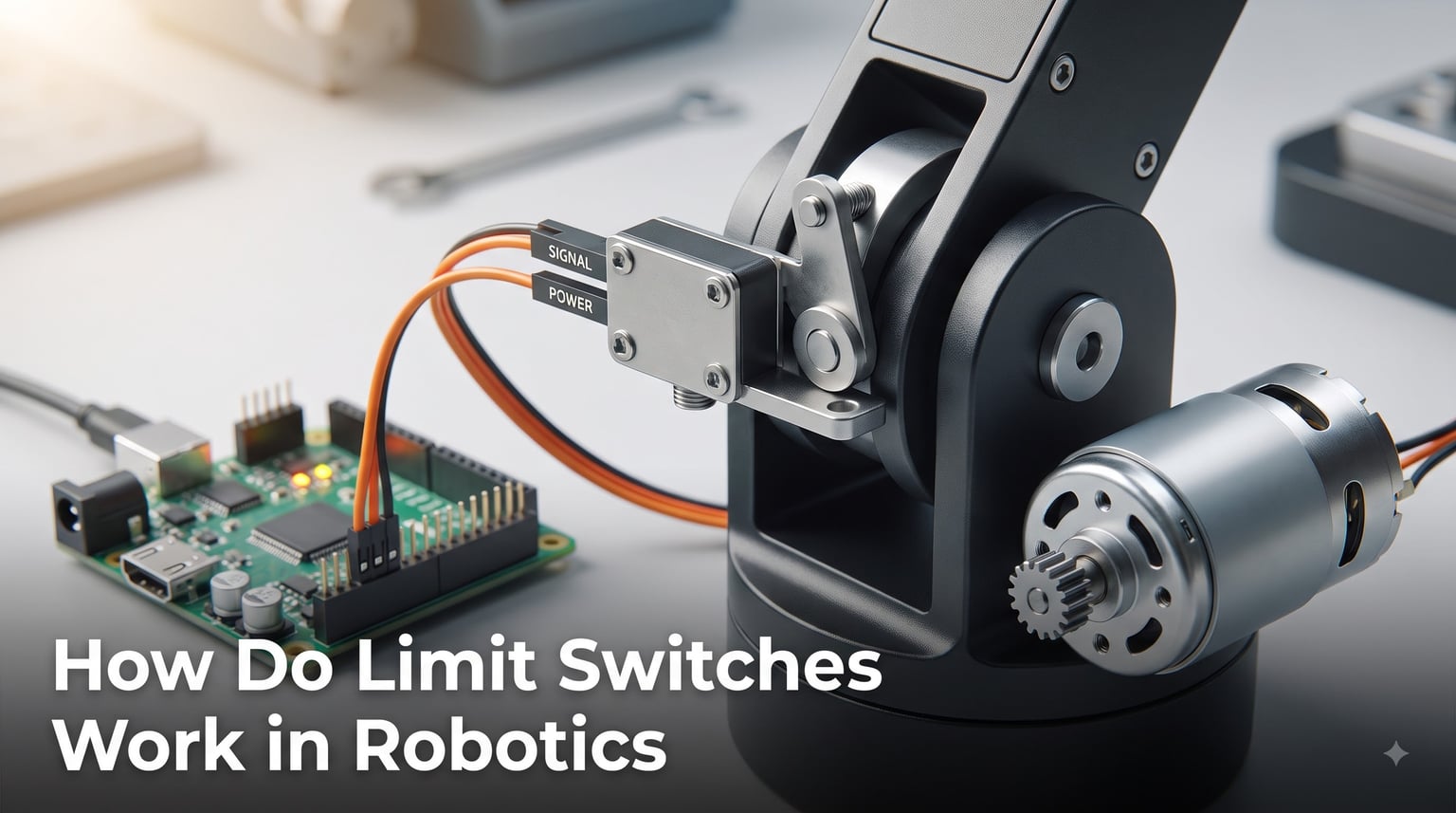
If you have ever watched a robotic arm stop exactly at its home position or seen a 3D printer know when it reached the edge of its rail, you have witnessed a limit switch in action. These small electromechanical components are among the most reliable and widely used sensors in all of robotics. They tell a robot’s control system when something has moved to a specific physical position, making them essential for safe and repeatable operation.
In this guide, we explain exactly how limit switches work in robotics, covering the working principle, types, wiring, programming, and real-world applications. Whether you are building an FRC competition robot, an Arduino-based gripper, or an industrial automation project, understanding these devices will save you time and prevent costly damage to your hardware.
We have pulled insights from robotics forums, FRC and FTC competition teams, and experienced builders to address the real problems people face. From false triggering to choosing between limit switches and encoders, we cover the questions that come up most. For related context on robotic grippers and tactile sensing, limit switches are often the unsung heroes that make reliable grasping possible.
Table of Contents
What Is a Limit Switch in Robotics?
A limit switch is an electromechanical device that detects the physical presence or position of a moving object and converts that mechanical contact into an electrical signal. When something presses against the switch’s actuator, internal contacts open or close a circuit. That change in electrical state tells the robot’s controller that a specific physical position has been reached.
In robotics, this translates to a simple binary input: the switch is either triggered or it is not. That makes limit switches incredibly straightforward to read with any microcontroller. You do not need analog-to-digital conversion or complex signal processing to know if your robotic arm has hit its travel limit.
The core components of every limit switch are the actuator (the part that gets physically pushed), the internal contacts (which open or close the circuit), and the terminals (where you connect your wires). The actuator type determines how the switch responds to contact, and the contact arrangement determines what electrical signal it produces.
How Do Limit Switches Work in Robotics
The working principle of a limit switch comes down to a straightforward mechanical-to-electrical conversion. Here is what happens step by step when a limit switch operates in a robotic system.
Step 1: Physical Contact
A moving part of the robot, such as a robotic arm joint, a gantry carriage, or a gripper finger, makes physical contact with the switch’s actuator. The actuator might be a lever, a roller, a plunger, or a flexible whisker. The robot must actually touch the switch, because limit switches require physical interaction to function.
Step 2: Mechanical Actuation
The actuator moves internally, typically through a spring-loaded mechanism. This mechanical movement physically pushes or releases a set of electrical contacts inside the switch body. The design ensures that a small amount of travel at the actuator translates into a definite, snap-action change in the contact state.
Step 3: Circuit State Change
The internal contacts change state, either opening or closing the electrical circuit connected to the switch terminals. If you wired the switch as normally open, the circuit closes on contact. If you wired it as normally closed, the circuit opens on contact. We cover these configurations in detail later in this guide.
Step 4: Digital Signal Sent to Controller
Your robot’s microcontroller, whether that is an Arduino, a Raspberry Pi, or a roboRIO, reads this circuit change as a digital input. The controller sees either a HIGH or LOW signal on the pin connected to the switch. This is the raw position data your program uses to make decisions.
Step 5: Software Response
Your code reacts to the signal. A common response is to immediately stop a motor to prevent the mechanism from traveling further and hitting a hard mechanical stop. Another common pattern is to use the trigger event to establish a known home or zero position, which is fundamental to how most 3D printers and CNC machines initialize their axes.
That entire sequence, from physical contact to software response, happens in milliseconds. The mechanical nature of the switch means there is no ambiguity about whether contact occurred, which is why these devices remain trusted in safety-critical applications despite the availability of more advanced sensors.
Types of Limit Switches Used in Robotics
There are four primary types of limit switches that robotics builders encounter, each with a different actuator design suited to specific applications. Understanding the differences helps you pick the right switch for your mechanism.
1. Whisker Limit Switches
Whisker switches use a thin, flexible metal wire or spring as the actuator. When an object touches the whisker, it bends and triggers the internal contact. These are popular in FTC and FRC robotics for detecting objects without requiring precise positioning, because the flexible whisker can catch contact across a wider area. Robotic grippers frequently use whisker switches for object detection and grasp confirmation.
2. Roller Lever Limit Switches
Roller lever switches feature a small wheel at the end of a pivoting arm. The roller reduces friction when a moving part slides along the actuator, making them ideal for conveyor systems, cam-following mechanisms, and linear motion stages where the actuating part passes across the switch rather than pressing straight into it. The lever arm provides leverage, so even light contact can trigger the switch reliably.
3. Plunger Limit Switches
Plunger switches have a pushbutton-style actuator that must be pressed directly along its axis. They offer precise, repeatable triggering but require the contacting part to hit them squarely. These are common in applications where the moving part moves directly toward the switch, such as a piston reaching the end of its stroke or a Z-axis carriage hitting its top limit.
4. Lever Arm Limit Switches
Lever arm switches use a solid metal arm without a roller. They work similarly to roller lever types but provide more direct mechanical feedback. The arm length can often be adjusted or bent to fit tight mounting spaces, which makes them versatile for custom robotics projects where space is at a premium.
Most robotics hobbyist projects use miniature snap-action switches, often called microswitches, regardless of actuator type. These small, inexpensive switches are the kind you will find on 3D printers and in FRC kit supplies. They are reliable, cheap, and available with all four actuator styles.
Electrical Configurations: Normally Open vs Normally Closed
The way a limit switch is wired electrically determines how your robot responds if something goes wrong. This is one of the most important design decisions in robotics sensor integration, because it directly affects safety.
Normally Open (NO)
In a normally open configuration, the switch’s contacts are open when nothing is pressing the actuator. The circuit is incomplete, and the controller reads the default state. When an object hits the switch, the contacts close and the controller detects the trigger.
The risk with NO wiring is that if the wire breaks or a connection comes loose, the controller cannot tell the difference between no contact and a broken circuit. Both look the same, which means a failure goes undetected. For non-critical applications like homing routines, this is usually fine.
Normally Closed (NC)
In a normally closed configuration, the contacts are closed by default and the controller constantly reads a signal. When an object hits the switch, the contacts open and the controller detects the change.
NC wiring is the preferred choice for safety-critical applications. If a wire breaks, the circuit opens, and the controller immediately detects the loss of signal. It can then treat that as a fault condition and stop the mechanism. Experienced robotics builders on forums consistently recommend NC configurations for any safety-related limit switch.
SPDT and DPDT Options
Many limit switches offer both NO and NC terminals on the same device, which is called a single-pole double-throw (SPDT) configuration. This gives you flexibility to choose your wiring approach without buying a different switch. Double-pole double-throw (DPDT) switches offer two independent sets of contacts, which is useful if you need to send signals to two different systems or want redundancy.
For most robotics projects, a standard SPDT microswitch gives you everything you need. You get common, normally open, and normally closed terminals on one small, inexpensive device.
Wiring Limit Switches to Microcontrollers
Wiring a limit switch to a microcontroller is straightforward once you understand pull-up resistors. The most common approach in robotics is to use the microcontroller’s internal pull-up resistor and wire the switch between the input pin and ground.
When the switch is not triggered, the pull-up resistor keeps the pin HIGH. When the switch activates and connects the pin to ground, the pin reads LOW. This means the default untriggered state reads as HIGH and the triggered state reads as LOW, which is a convention most Arduino and Raspberry Pi robotics code follows.
Arduino Wiring
Connect one switch terminal to a digital input pin and the other to ground. In your Arduino code, use pinMode(pin, INPUT_PULLUP) to enable the internal pull-up resistor. You then read the switch with digitalRead, and the pin will return LOW when triggered.
Raspberry Pi Wiring
The same approach works on a Raspberry Pi using GPIO pins. You can enable the internal pull-up resistor in software through libraries like RPi.GPIO or gpiozero. Connect the switch between a GPIO pin and ground, and read the state in your Python script.
Debouncing
Because limit switches are mechanical devices, the contacts bounce when they close or open. This bouncing can produce multiple rapid transitions that your microcontroller might read as multiple triggers. You handle this in software with a debounce routine, which waits a few milliseconds after detecting a change before reading the pin again. Hardware debouncing with a small capacitor is also common in more permanent builds.
For safe wiring practices that go beyond sensor connections, see our guide on robot power system wiring to ensure your entire electrical system is set up correctly.
Programming Limit Switches for Robotics
Programming a limit switch is one of the simplest tasks in robotics software. At its core, you read a digital input and make a decision based on the result. The complexity comes from how you use that information to control your robot.
Basic Motor Control
The most common programming pattern is to stop a motor when the switch triggers. Your main control loop continuously reads the switch state. If the switch is triggered, the code commands the motor controller to stop or reverse. This prevents the mechanism from pushing past its physical limit and causing damage.
Homing Routines
Homing is the process of establishing a known zero position. The robot slowly moves the axis toward the limit switch. When the switch triggers, the code records that position as zero and stops the motor. From that known reference, all subsequent movements can be measured. This is how 3D printers, CNC machines, and robotic arms initialize themselves at startup.
Using Limit Switches with Encoders
Many advanced robots combine limit switches with encoders. The encoder provides continuous position tracking, while the limit switch provides an absolute reference point for homing. Together, they give you both precision and repeatability. This combination comes up constantly in forum discussions among robotics builders who want reliable position feedback.
Position feedback from limit switches also relates directly to robotic arm positioning and kinematics, where knowing the exact position of each joint is essential for accurate movement control.
Limit Switch vs Encoder: Which Should You Use?
This is one of the most frequently asked questions in robotics forums, and the answer depends on what your mechanism needs to do. The two sensors serve related but different purposes.
A limit switch tells you whether a mechanism has reached one specific position. It provides binary, point-to-point feedback. An encoder tells you the continuous position of a rotating shaft or linear axis throughout its entire range of motion. It provides real-time tracking at every point.
When to Use a Limit Switch Alone
Limit switches are ideal when you only need to detect a boundary or end stop. If your robotic arm just needs to know when it has reached its maximum extension, a limit switch does that job perfectly at a fraction of the cost and complexity of an encoder. They are also the right choice for simple object detection, such as sensing whether a part is present on a conveyor.
When to Use an Encoder Alone
Encoders make sense when your robot needs to move to multiple specific positions or when you need precise speed control. If a robotic arm needs to move to ten different angles with high accuracy, an encoder gives you the continuous feedback to achieve that. The tradeoff is higher cost and more complex programming.
Using Both Together
The most robust approach, and the one recommended by experienced builders on Reddit’s r/AskRobotics, is to use both. The encoder handles everyday position tracking, and the limit switch provides a reliable home reference plus a safety backup. If the encoder loses track of its position due to a power loss or wheel slip, the limit switch lets the robot recalibrate.
Forum users consistently report that this dual-sensor approach gives the best of both worlds. The limit switch costs almost nothing but adds a layer of safety and reliability that an encoder alone cannot provide.
Common Robotics Applications for Limit Switches
Limit switches appear in an enormous range of robotics applications. Here are the most common scenarios where builders rely on them.
Robotic Arm End Stops
Every joint on a robotic arm has a mechanical limit to how far it can rotate or extend. Limit switches detect when the arm reaches that limit and signal the controller to stop the motor. This prevents gears from grinding, servos from burning out, and linkages from bending. The end effector at the arm’s tip often has its own switches for object detection.
Gripper Object Detection
When a robotic gripper closes on an object, it needs to know when it has made contact. A whisker or plunger limit switch mounted on the gripper fingers triggers the moment the object is touched. The controller then stops the closing motion, preventing the gripper from crushing the object or stalling its motor.
Conveyor and Elevator Systems
In automated material handling, limit switches detect when items reach specific points along a conveyor. Elevator mechanisms use them at the top and bottom of travel to prevent overtravel. These applications are common in FRC competition robots that lift game pieces to scoring heights.
3D Printers and CNC Machines
Every desktop 3D printer uses limit switches (or sometimes optical end stops) on each axis for homing. The printer slowly moves each axis until the switch triggers, establishing the zero position for that axis. CNC machines use the same principle to know where the cutting tool is relative to the workpiece.
Autonomous Robot Navigation
Some autonomous robots use limit switches as bump sensors. When the robot runs into a wall or obstacle, the switch triggers and the robot backs up or changes direction. This is a simple but effective collision detection method for low-cost robots, and it ties into robot chassis design and sensor placement.
Advantages and Disadvantages of Limit Switches in Robotics
Limit switches are popular for good reasons, but they also have real limitations. Understanding both sides helps you decide when to use them and when to consider alternatives.
Advantages
Limit switches are inexpensive and widely available. A standard microswitch costs less than a dollar and can be purchased anywhere electronics parts are sold. Their simplicity means there is almost nothing to go wrong in the signal chain, and no complex programming is required for basic operation.
They provide direct, unambiguous physical feedback. The switch either made contact or it did not. This binary certainty is valued in safety-critical applications where false readings could cause damage or injury. They also work without any microcontroller at all for basic circuit-level safety interlocks.
Forum users and FRC teams consistently praise limit switches for their reliability compared to more complex sensors. When properly wired with normally closed contacts, they can even fail safely by alerting the controller when a wire breaks.
Disadvantages
The biggest disadvantage of a limit switch is mechanical wear. Because the switch relies on physical contact, moving parts eventually wear out. Contacts can pit, springs can fatigue, and actuators can bend. In high-cycle applications, switches need periodic replacement.
Limit switches can only detect a single position per switch. They cannot tell you how far something has traveled or how fast it is moving. If your application needs continuous position data, you need an encoder or potentiometer instead.
False triggering is a common complaint, especially from vibration and electrical noise. Users on Reddit frequently report switches that seem to trigger without being touched, which usually comes down to wiring or debounce issues rather than the switch itself.
They require physical contact to function. This means the robot must actually reach the switch location, which is not always practical. For non-contact detection, proximity sensors or optical sensors may be a better choice.
Troubleshooting Limit Switch Problems
Even though limit switches are simple devices, they can still cause frustrating problems in robotics projects. Here are the most common issues and how to fix them.
False Triggering from Vibration and Noise
This is the single most common complaint in robotics forums. A limit switch appears to trigger without being physically contacted, causing a robot to stop or behave erratically. The cause is almost always electrical noise or inadequate pull-up resistance. Fix this by ensuring proper pull-up resistors, keeping switch wires short and away from motor wires, and adding a debounce routine in software. A small capacitor across the switch terminals can also filter noise.
Intermittent Switch Behavior
If your switch works sometimes but not others, check for mechanical issues first. The actuator might not be making full contact, or the mounting bracket could be flexing. Loose wire connections are another frequent culprit. Crimp connectors that have not been properly crimped can cause intermittent opens that look like switch failures.
Testing with a Multimeter
You can test any limit switch with a digital multimeter set to continuity or resistance mode. Connect the probes to the common and normally closed terminals. You should read near-zero ohms when the switch is at rest and infinite resistance when actuated. Experienced builders recommend always testing switches before installation.
Switch Not Triggering at All
If the switch never triggers, verify your wiring first. Make sure you are connected to the correct terminals for your desired configuration. Check that the actuator is being physically engaged by the moving part. Finally, confirm that your code is reading the correct pin and interpreting the signal polarity correctly.
Power-related issues can also affect sensor reliability. If your robot’s voltage drops under load, microcontroller pins can behave unpredictably. For more on this topic, see our article on robot power issues and sensor reliability.
Tips for Choosing the Right Limit Switch
Selecting the right limit switch for your robotics project comes down to matching the switch characteristics to your application requirements. Here are the key factors to consider.
Consider the actuator type first. If your mechanism slides across the switch, choose a roller lever. If it presses straight in, a plunger works well. For wide-area object detection, a whisker switch gives you the most forgiving contact zone.
Check the voltage and current ratings. Most microswitches handle 5V DC easily, which covers Arduino, Raspberry Pi, and roboRIO applications. Industrial switches may be rated for higher voltages and currents, which matters if the switch controls a load directly rather than just sending a signal to a controller.
Think about environmental conditions. If your robot operates in dusty, wet, or harsh environments, look for sealed switches with appropriate IP ratings. Standard open-frame microswitches are fine for clean indoor use but can fail when exposed to debris or moisture.
Finally, choose normally closed wiring for any safety-critical application. The small extra effort of wiring NC instead of NO provides fail-safe behavior that can prevent damage to your robot when something goes wrong.
What is a limit switch in robotics?
A limit switch in robotics is an electromechanical device that detects the physical position of moving parts by converting mechanical contact into an electrical signal. When a robot component presses against the switch actuator, internal contacts open or close a circuit, telling the controller that a specific position has been reached.
How do limit switches work?
Limit switches work by converting physical contact into an electrical signal. A moving part hits the switch actuator (lever, plunger, roller, or whisker), which mechanically changes the state of internal electrical contacts. The controller reads this change as a digital input and responds, typically by stopping a motor or recording a home position.
What is a disadvantage of a limit switch?
The main disadvantage of a limit switch is mechanical wear from physical contact, which eventually leads to failure. They also only detect a single position per switch, cannot provide continuous position data, and require the robot to physically reach the switch location. They can also be prone to false triggering from vibration and electrical noise if not properly wired and debounced.
What are the 4 types of limit switches?
The four common types of limit switches used in robotics are whisker switches (flexible wire for wide-area detection), roller lever switches (rolling contact for sliding mechanisms), plunger switches (direct pushbutton for axial contact), and lever arm switches (solid arm for versatile mounting). Each type suits different contact patterns and spatial constraints.
Should I use normally open or normally closed for a safety limit switch?
Use normally closed (NC) wiring for safety-critical limit switches. If a wire breaks in an NC configuration, the circuit opens and the controller detects the fault. In a normally open (NO) configuration, a broken wire looks the same as no contact, meaning the failure goes undetected and the safety system is silently disabled.
Do I need both a limit switch and an encoder?
For many robotics applications, using both is the best approach. The encoder provides continuous position tracking and precise movement, while the limit switch provides a reliable home reference and safety backup. This dual-sensor strategy is widely recommended by experienced builders because it combines precision with fail-safe reliability.
Conclusion
Limit switches are fundamental components in robotics that convert physical contact into reliable electrical signals. They work through a simple five-step process: physical contact, mechanical actuation, circuit state change, digital signal transmission, and software response. Despite the availability of more advanced sensors, their simplicity, low cost, and proven reliability keep them at the center of robotics design.
Understanding how do limit switches work in robotics means knowing the four actuator types (whisker, roller lever, plunger, and lever arm), the difference between normally open and normally closed wiring, and when to pair them with encoders for more robust position sensing. For safety-critical applications, always wire your switches as normally closed so that broken wires are detected as faults rather than silent failures.
If you are starting a robotics project, begin by identifying where your mechanisms need position feedback and boundary detection. Add limit switches at those points, wire them with proper pull-up resistors and debouncing, and test thoroughly with a multimeter before final installation. These small, inexpensive devices can prevent expensive damage to your robot and give you the reliable operation that every successful project depends on.