
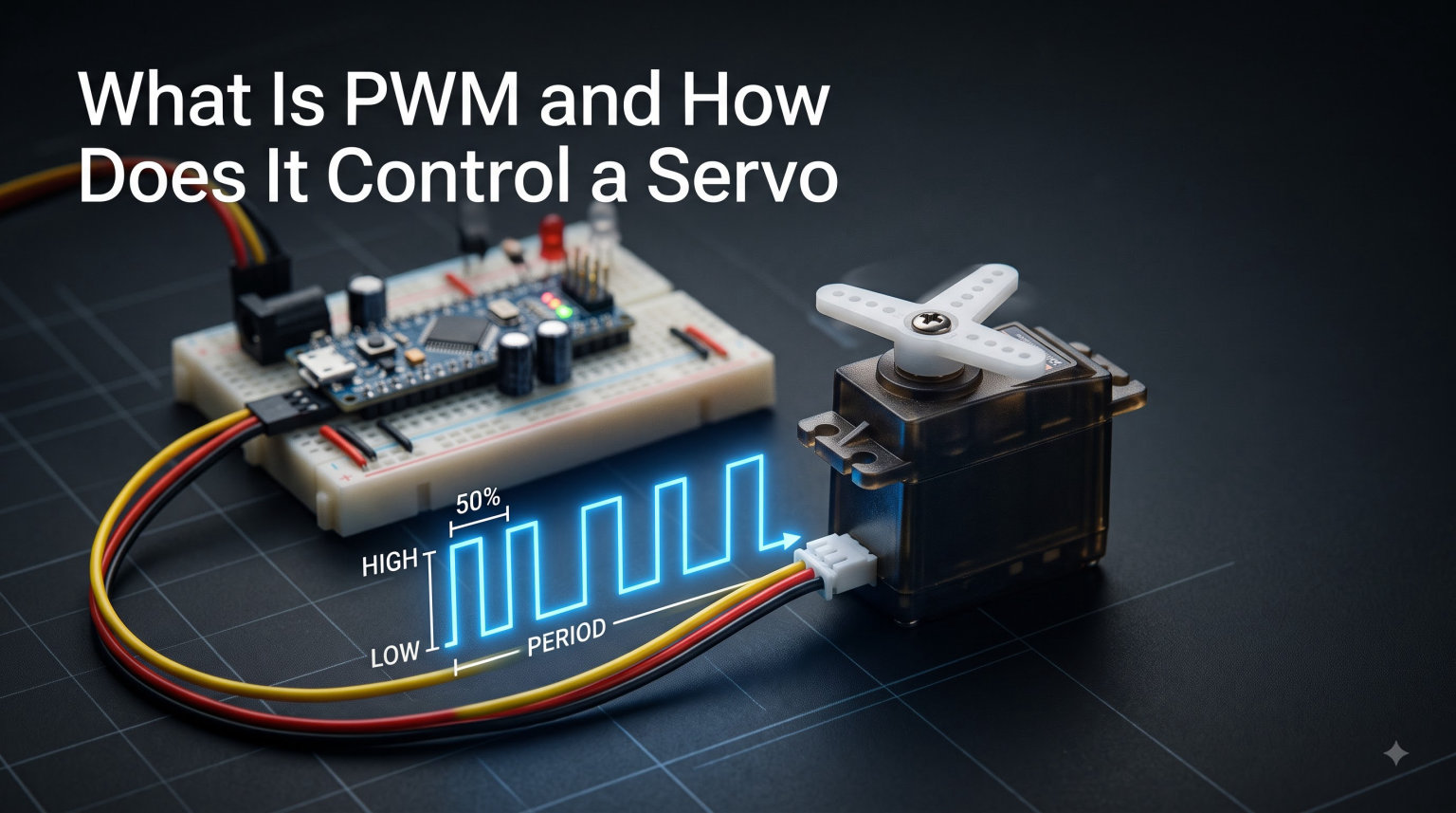
PWM servo control is the signaling method that tells a hobby servo exactly where to point its shaft. Every RC car steering linkage, robot arm joint, and drone gimbal relies on these tiny electrical pulses to move with precision. If you have ever wondered why your servo jitters, why it only responds at 50Hz, or what those mysterious 1.5ms numbers mean, this guide breaks it all down.
In this article, we will walk through what PWM is, how it maps pulse width to servo angle, and how to wire up an Arduino example step by step. We will also cover the difference between PWM and PPM, plus digital versus analog servos. These last two topics are where most competing guides fall short.
By the end, you will understand PWM servo control well enough to build, debug, and tune your own servo-driven projects with confidence.
Table of Contents
What Is PWM and How Does It Control a Servo?
PWM stands for Pulse Width Modulation, a technique where a digital signal switches between high and low voltage at a fixed frequency to carry information. The “width” of each high-voltage pulse is what matters for servo control. That pulse width tells the motor exactly which angle to hold.
A standard hobby servo expects a pulse between 1 millisecond and 2 milliseconds, repeated roughly every 20 milliseconds. A 1ms pulse commands full counterclockwise rotation. A 2ms pulse commands full clockwise rotation. A 1.5ms pulse places the servo at its neutral center position.
The servo’s internal circuitry measures each incoming pulse and compares it against the current shaft position. If there is a difference, the built-in motor drives the shaft toward the commanded angle. Once the target is reached, the servo holds that position as long as the signal keeps arriving.
This is what makes servos different from regular DC motors. A DC motor spins continuously while power is applied. A servo moves to a specific angle and stays there, which is why PWM servo control is the backbone of precise robotics.
The Anatomy of a PWM Signal
Every PWM signal has three defining properties: frequency, period, and pulse width. Frequency measures how many complete cycles happen per second, expressed in Hertz. Period is the total time for one complete cycle, calculated as the inverse of frequency.
Pulse width is how long the signal stays high during each cycle. For a servo running at 50Hz, the period is 20ms (1 divided by 50 equals 0.02 seconds). Within that 20ms window, only a tiny sliver of time, between 1 and 2ms, is spent in the high state.
The remaining 18ms, the signal sits low, waiting for the next pulse. This means the duty cycle for servo control ranges from just 5% to 10%. That is a critical difference from PWM used for LED dimming or motor speed control, where duty cycle might swing from 0% all the way to 100%.
Servo PWM Timing Specifications: 1ms, 1.5ms, and 2ms
The relationship between pulse width and servo angle follows a predictable linear scale. Most hobby servos interpret 1ms as the minimum position and 2ms as the maximum. Everything in between maps proportionally to an angle across the servo’s travel range, typically 180 degrees.
Here is the standard mapping that nearly all RC servos follow:
1.0ms pulse — Full counterclockwise position (commonly 0 degrees)
1.5ms pulse — Neutral center position (commonly 90 degrees)
2.0ms pulse — Full clockwise position (commonly 180 degrees)
Some servos accept pulses slightly outside this range, as narrow as 0.5ms or as wide as 2.5ms. But pushing beyond the rated range can damage the internal gears or burn out the motor. Always check your servo’s datasheet before experimenting with extended travel limits.
This timing standard dates back to the analog radio-control systems of the 1970s, and it has remained the universal convention ever since. Whether you buy a cheap SG90 micro servo or a high-torque metal-gear model, the same 1ms-to-2ms rule applies.
Converting Pulse Width to Angle
Since the servo interprets pulse width linearly, you can calculate the exact pulse duration for any target angle. Each additional millisecond of pulse width corresponds to roughly 180 degrees of rotation.
For a 180-degree servo, every microsecond of pulse width change moves the shaft approximately 0.18 degrees. A pulse of 1.25ms positions the servo at about 45 degrees. A pulse of 1.75ms reaches approximately 135 degrees.
This linear relationship is why microcontrollers can command precise positions simply by adjusting a single timing value.
The 50Hz Refresh Rate Explained
Servos expect their control signal to repeat at approximately 50Hz, meaning a fresh pulse arrives every 20 milliseconds. This refresh rate keeps the servo’s internal controller continuously updated on where the shaft should be positioned.
The 50Hz figure is a convention, not a hard physical law. The original analog radio-control systems settled on this rate decades ago, and it became the standard across the hobby industry. Every standard RC servo manufactured today still expects it.
In practice, servos tolerate a surprisingly wide range of refresh rates. Most will function reliably anywhere from 40Hz to 200Hz. Slower refresh rates, below 40Hz, can cause the servo to lose holding torque and relax between pulses. Faster rates, above 200Hz on an analog servo, may cause confusion or overheating.
Refresh Rate Tolerance and Digital Servos
Digital servos can handle much higher refresh rates, sometimes 333Hz or more. This faster update rate gives digital servos their characteristic holding power and snappy responsiveness. Analog servos, by contrast, are optimized for the standard 50Hz and do not benefit from higher refresh rates.
If you are building a project that controls multiple servos, the refresh rate also determines how smoothly everything moves. A controller that updates each servo in sequence at 50Hz will command all of them 50 times per second, which is smooth enough for most mechanical movements.
Pulse Width vs Duty Cycle: A Common Source of Confusion
One of the biggest misunderstandings in the Arduino community is the relationship between pulse width and duty cycle. They are related concepts, but they serve completely different purposes in PWM servo control.
Duty cycle is the percentage of one period that the signal spends in the high state. For a 50Hz signal with a 1.5ms pulse, the duty cycle is 7.5%. But the servo does not care about this percentage at all. It cares about the absolute duration of the high pulse, measured in milliseconds.
As one Arduino forum contributor explained: PWM involves the modulation of a signal’s duty cycle, but in controlling a servo, the duty cycle does not control the position. What controls position is the absolute pulse width.
This distinction matters because standard Arduino PWM outputs, generated by the analogWrite function, produce signals at 490Hz or 980Hz. These frequencies are wrong for servos. The Arduino Servo library works around this by producing the correct 50Hz timing on dedicated pins, rather than relying on the hardware PWM channels.
If you tried to drive a servo with raw analogWrite output, the servo would receive thousands of pulses per second instead of 50. It would interpret each tiny high-time as a valid pulse width, resulting in erratic behavior or no response at all.
PWM vs PPM: What Is the Difference?
PWM and PPM are two different signal formats that often appear in the same RC electronics catalogs. PWM (Pulse Width Modulation) is the signal that an individual servo understands. PPM (Pulse Position Modulation) is an encoding scheme used to transmit multiple servo channels over a single wire or radio link.
With PWM, each servo needs its own dedicated signal wire from the receiver or controller carrying one pulse between 1ms and 2ms, repeated at 50Hz. This is point-to-point communication. A six-channel RC system using PWM requires six separate signal wires running from the receiver to the servos.
With PPM, multiple channels are encoded back-to-back within each 20ms frame on a single wire. A sync gap, which is a longer pause between frames, tells the receiver where one frame ends and the next begins. The receiver then decodes the PPM stream and splits it back into individual PWM signals for each servo output.
Here is a quick comparison:
PWM — One wire per servo, one pulse per frame, 1ms to 2ms width
PPM — One wire for all channels, multiple pulses per frame separated by gaps, decoded into PWM at the receiver
In practice, modern 2.4GHz radio systems often use digital protocols like SBUS or IBUS internally, which are even more efficient than PPM. But the individual servo outputs on your receiver are always PWM, because that is what the servo hardware expects.
If you are working with an Arduino, you will almost always deal directly with PWM. PPM becomes relevant when you are interfacing with RC transmitters, receivers, or flight controllers that aggregate multiple channels into a single stream.
Digital vs Analog Servos: How Each Handles PWM
Both digital and analog servos use the same PWM signal format at the input. They both accept 1ms to 2ms pulses at 50Hz on the signal wire. The difference lies entirely in how their internal electronics process that signal to drive the motor.
Analog servos use a simple comparator circuit that reads the incoming PWM pulse and drives the motor at full voltage whenever a position error exists. They update their motor drive at the same 50Hz rate as the incoming signal. This means the motor receives power in short bursts, roughly every 20ms, which produces a slight dead band where small position errors go uncorrected.
Digital servos contain a small microcontroller that processes the incoming PWM signal at a much higher internal rate, often 300Hz or more. Even though the incoming signal is still 50Hz, the digital controller commands the motor far more frequently per second. This gives digital servos noticeably higher holding torque, faster response times, and smoother movement throughout the travel range.
The trade-off is power consumption and noise. Digital servos draw more current because they drive the motor more aggressively and more often. They also generate more heat and can produce an audible high-frequency whine during operation.
For most hobby projects, analog servos are perfectly adequate and far more affordable. Digital servos earn their higher price tag when you need precise holding force under load. Think robotic grippers that must resist external forces, camera gimbals that need vibration-free stability, or fast RC steering where every millisecond of response time counts.
Connecting a Servo to Arduino: Step-by-Step
Wiring a servo to an Arduino is one of the most common first projects in robotics. Here is a step-by-step guide that works with any standard hobby servo and an Arduino Uno or compatible board.
Step 1: Identify the servo wires. Most hobby servos have three color-coded wires. The brown or black wire is ground. The red wire is positive power, typically 5V or 6V. The yellow, orange, or white wire is the PWM signal wire that carries the position command.
Step 2: Make the connections. Connect the servo ground wire to a GND pin on the Arduino. Connect the servo power wire to the 5V pin for small servos under light load, or to an external 5V to 6V power supply for larger motors. Connect the signal wire to digital pin 9.
Step 3: Handle power correctly. Small servos like the SG90 can often run directly from the Arduino 5V pin during quick tests. Larger servos, anything pulling more than 500mA under load, should use an external power supply to avoid brownouts and potential USB port damage. Always connect the ground of the external supply to the Arduino ground.
Step 4: Consider signal voltage. Most servos work with both 3.3V and 5V logic signals, though 5V is more reliable over longer wire runs. If you are using a 3.3V microcontroller like a Raspberry Pi Pico and experiencing intermittent response, a logic-level converter can help.
Arduino Servo Code Example
The Arduino IDE includes a built-in Servo library that handles the 50Hz PWM timing for you. Here is a minimal sketch that sweeps the servo through its full range:
#include <Servo.h>

Servo myServo;  // create servo object

void setup() {
  myServo.attach(9);  // attach servo to pin 9
}

void loop() {
  myServo.write(0);    // full counterclockwise (~1ms pulse)
  delay(1000);
  myServo.write(90);   // center position (~1.5ms pulse)
  delay(1000);
  myServo.write(180);  // full clockwise (~2ms pulse)
  delay(1000);
}
The write() function accepts an angle in degrees from 0 to 180. Internally, the library converts this angle to the correct pulse width and generates the 50Hz PWM signal on the specified pin. You can also use writeMicroseconds() to send raw pulse values directly, which gives finer control for servos with extended travel ranges.
You can generate servo pulses manually using digitalWrite and delayMicroseconds instead of the library. This approach works on any digital pin, not just hardware PWM pins. The trade-off is that your main loop must carefully maintain the 20ms refresh interval, which can interfere with other timing-sensitive code.
Troubleshooting Common Servo PWM Issues
Even with correct wiring, servos can behave unpredictably. Here are the most common problems we have encountered and their fixes.
Servo jitters or moves erratically. This is almost always a power issue. Servos draw sharp current spikes when they move, and an undersized power supply causes voltage drops that reset or confuse the microcontroller. Use a dedicated power supply rated for at least 1 amp per servo, and add a large capacitor (470uF to 1000uF) across the power rails to absorb transient spikes.
Servo does not hold position. If the servo drifts or goes slack, the refresh rate may be too low. Ensure your code sends a fresh pulse at least every 20ms. If you are doing heavy processing in your main loop, the servo updates may be delayed. Consider using a timer interrupt to maintain consistent pulse timing.
Servo only moves in one direction. Check that your pulse width range is correct. If you are only generating pulses between 1.5ms and 2ms, the servo will only travel across half its range. Make sure your code spans the full 1ms to 2ms window for complete rotation.
Signal degradation over long wires. PWM signals degrade over long wire runs due to resistance and noise pickup. If your servo is more than a few feet from the controller, use a signal booster or a shielded twisted-pair cable. A practical recommendation from experienced builders is to keep signal wires under 24 inches for reliable operation without amplification.
FAQs
Does a servo need PWM?
Yes, a servo needs a PWM signal to know which position to hold. The servo measures the width of each incoming pulse, typically between 1ms and 2ms, and moves its shaft to the corresponding angle. Without a repeating PWM signal, the servo has no position command and will go limp or hold its last position with reduced torque.
What is the normal PWM range for servos?
The standard PWM range for hobby servos is 1ms to 2ms pulse width, repeated at 50Hz (every 20ms). A 1ms pulse commands full counterclockwise rotation, 1.5ms sets the neutral center, and 2ms commands full clockwise rotation. Some servos accept extended ranges of 0.5ms to 2.5ms, but always verify against the datasheet to avoid gear or motor damage.
How is PWM controlled?
PWM is controlled by a microcontroller, servo controller board, or RC receiver that generates a digital signal switching between high and low voltage. The controller varies the duration of the high-voltage pulse (1ms to 2ms for servos) while maintaining a fixed 50Hz repetition rate. On an Arduino, the Servo library handles this timing automatically using hardware timers.
What are the disadvantages of PWM controllers?
PWM controllers for servos have a few drawbacks. Each servo needs its own dedicated signal wire, which creates wiring complexity in multi-servo projects. The 50Hz refresh rate limits how quickly a servo can update its position. Analog PWM servos have a dead band where small errors go uncorrected, and long signal wires can pick up noise without proper shielding or signal boosters.
What is the difference between PWM and PPM?
PWM (Pulse Width Modulation) is the signal format that an individual servo understands, carried on one dedicated wire per servo. PPM (Pulse Position Modulation) encodes multiple servo channels into a single signal stream, with pulses arranged back-to-back within each 20ms frame. A receiver decodes PPM back into individual PWM signals for each servo output. Most Arduino projects use PWM directly.
Why does my servo jitter or move erratically?
Servo jitter is almost always caused by an inadequate power supply. Servos draw sharp current spikes when moving, and a weak supply causes voltage drops that reset the microcontroller. Use a dedicated power source rated for at least 1 amp per servo, share a common ground between the supply and microcontroller, and add a 470uF to 1000uF capacitor across the power rails to absorb transient spikes.
Conclusion
Understanding PWM servo control comes down to grasping a few core principles. A servo reads the width of each incoming pulse, typically between 1ms and 2ms, and translates that duration into a precise shaft angle. The signal repeats at 50Hz to keep the servo continuously updated and holding its position.
We covered the difference between pulse width and duty cycle, which trips up many beginners, and compared PWM to PPM for multi-channel applications. We also explored how digital and analog servos handle the same PWM signal differently, plus a full Arduino wiring example and troubleshooting guide for common issues.
Your next step is to wire up a servo, load the example sketch, and experiment with different pulse values. Once you can command a single servo reliably, you can scale up to multi-servo robots, RC vehicles, and automation projects of your own.