
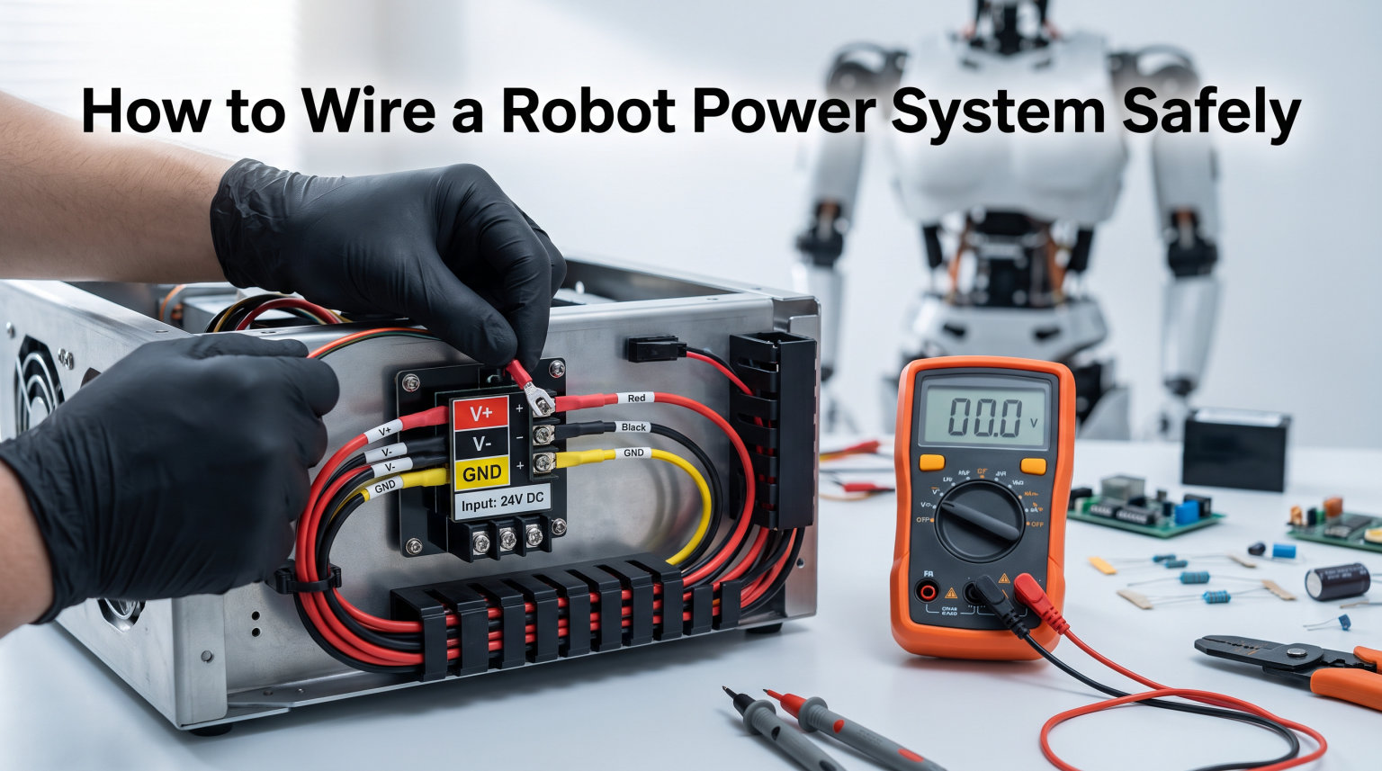
Learning how to wire a robot power system safely is the single most important skill in robotics. A poorly wired robot can catch fire, damage expensive components, or deliver a shock the moment you touch the chassis. Yet most beginner guides skip the safety fundamentals and jump straight to plugging things in.
Our team has spent years building competition robots, hobby projects, and industrial systems. Along the way we have seen every wiring mistake imaginable, from undersized wires melting at motor connections to ground loops that made servos twitch uncontrollably. Every one of those failures traces back to a handful of avoidable errors.
This guide walks you through the complete process of building a robot power system from scratch. You will learn how to choose the right wire gauge, follow color coding standards, set up power distribution, install fuses and breakers, ground your chassis, manage cables, separate signal from power lines, test with a multimeter, and follow a pre-power safety checklist. Whether you are building your first Arduino rover or wiring an FRC competition robot, these steps apply directly to your project.
By the end, you will have a clear, repeatable wiring process that keeps your robot running reliably and, more importantly, keeps you safe.
Table of Contents
Essential Safety Principles Before You Start
Safety in robot wiring is not a suggestion. It is the foundation that everything else rests on. Before you strip a single wire or connect a single battery, you need to understand the risks.
The most common danger is working on an energized circuit. Always disconnect the battery before touching any wiring. Community members on robotics forums consistently stress this point.
They recommend confirming the de-energized state with a multimeter before putting your hands anywhere near the electronics. A battery that looks disconnected can still hold a charge in capacitors. Treat every circuit as live until you have proven otherwise.
Fire risk is real. When current flows through a wire that is too thin for the load, the wire heats up. At high enough temperatures, insulation melts, smoke appears, and nearby components catch fire.
This is why wire gauge selection and fusing matter so much. We cover both in detail below. Getting these two things right eliminates the majority of fire hazards in a robot.
Work in a well-ventilated area with no flammable materials nearby. Keep a fire extinguisher rated for electrical fires within reach. Wear safety glasses when cutting wire or crimping terminals, because small metal fragments can fly unexpectedly.
Finally, never use a damaged battery. A swollen or punctured LiPo battery is a serious hazard. If you see any physical damage, stop and dispose of it properly before continuing.
How to Wire a Robot Power System Safely: Complete Step-by-Step
The process of wiring a robot power system breaks down into ten sequential steps. Follow them in order, because each step builds on the one before it. Skipping ahead, especially past fusing and grounding, is where most beginners get into trouble.
We recommend pre-wiring as many components as possible on your workbench before final assembly. Forum users consistently report that this approach saves hours of frustration. Soldering and crimping inside a cramped robot frame is far more difficult than doing it on a flat surface.
Step 1: Choose the Right Wire Gauge (AWG)
Wire gauge is measured using the American Wire Gauge (AWG) standard. The system works backwards from what you might expect. A lower AWG number means a thicker wire, and a thicker wire can carry more current safely.
Here is a practical reference for robot power wiring:
10 AWG handles up to 30A. Use this for main battery feeds and high-current motor controllers.
12 AWG handles up to 9.3A continuous. Many beginners assume 12 AWG is sufficient for everything, but forum users report it overheats with high-current loads.
14 AWG handles up to 5.9A. Suitable for mid-range motors and power distribution branches.
18 AWG handles up to 2.3A. Use for sensors, small servos, and low-power peripherals.
22 AWG handles up to 0.9A. Reserved for signal wires and LED indicators.
One of the most common pain points on robotics forums is undersized wire causing overheating. Users building servo-heavy projects discover that an MG996R servo can draw 15A at stall. If you are running multiple high-power servos, 12 AWG is simply not enough for the main power feed.
Always size your wire for the maximum possible current, not the typical running current. When in doubt, go one size thicker. The cost difference is negligible, and the safety margin is significant.
Stranded wire is preferred over solid wire for robots because it flexes without breaking. This matters enormously in moving assemblies where the wire bends repeatedly. Solid wire work-hardens and snaps after enough cycles.
Step 2: Follow Wire Color Coding Standards
Consistent color coding makes your robot wiring diagram readable and your troubleshooting process fast. When every wire is a different random color, debugging becomes guesswork. Forum users cite inconsistent color coding as one of their top frustrations when working on someone else’s robot.
Use this standard color convention for robot electrical systems:
Red for positive power lines (battery positive, motor power positive).
Black for ground and negative returns.
Yellow or white for signal wires (PWM, encoder data, sensor outputs).
Orange for switched power or secondary voltage rails.
Blue or green for CAN bus or communication lines.
Stick to this convention on every robot you build. When a problem appears, you will instantly know whether a wire carries power, ground, or signal just by looking at it. This saves enormous amounts of time during competitions or deadlines.
Label both ends of every wire with a small piece of heat shrink or a printed label. The few seconds this takes during assembly pays off massively when you need to disconnect and reconnect components for maintenance.
Step 3: Set Up Your Power Distribution
Power distribution is where your battery’s energy gets routed to every component that needs it. You do not wire components directly to the battery. Instead, you route power through a distribution point that allows fusing, voltage regulation, and organized branching.
Here is the standard power flow for a robot electrical system:
Connect the battery’s positive (red) terminal to a main fuse or circuit breaker.
Route from the main breaker to the input of a power distribution board or terminal block.
Attach the battery’s negative (black) terminal to the ground bus of the distribution board.
Run individual fused outputs from the distribution board to each motor controller.
Connect a dedicated fused output to your main controller or microcontroller board.
Add separate outputs for sensors, radio, and peripheral devices as needed.
This approach means every component has its own fuse and its own clean power path. If one motor controller shorts out, only its fuse blows. The rest of the robot stays alive, which is exactly what you want during operation.
Use a terminal block or power distribution board as the central hub. Terminal blocks are simple and inexpensive, while dedicated power distribution hubs offer built-in fusing and voltage monitoring. For competition robots, a power distribution hub with individual breaker slots per channel is the standard choice.
Step 4: Install Fuses and Circuit Breakers
Fuses and circuit breakers protect your robot from overcurrent events that would otherwise destroy components or start fires. The robotics community treats fusing as essential, not optional. A robot without fuses is an accident waiting to happen.
Place a main fuse or circuit breaker as close to the battery as possible. This protects the entire main power feed. If a short circuit develops anywhere downstream, the main breaker trips before the wiring overheats.
Beyond the main breaker, install individual fuses on each power branch. Here is how to select fuse ratings:
Match the fuse to the wire, not just the component. A fuse rated higher than the wire’s capacity will not protect the wire from overheating.
Size fuses at roughly 125% of the expected continuous current. This allows for startup surges while still protecting against sustained overcurrent.
Use slow-blow fuses for motor circuits. Motors draw high current for a fraction of a second at startup, and a fast-blow fuse will trip unnecessarily.
Use fast-blow fuses for sensitive electronics. Controllers and sensors need immediate protection from surge damage.
Keep spare fuses in your toolkit. During competitions and long build sessions, blown fuses are a routine occurrence. Having spares means you are back up and running in seconds rather than scrambling to find a replacement.
Step 5: Ground Your Robot Properly
Grounding is the most misunderstood aspect of robot wiring, yet it causes some of the most frustrating problems. When grounding is done wrong, you get shocked when touching the chassis, servos jitter erratically, and sensor readings become unreliable.
The first principle is creating a single, common ground point. Every component in your robot should connect back to one ground bus on the power distribution board. This is called a star ground configuration, and it prevents ground loops.
Ground loops happen when current finds multiple paths back to the battery. These circulating currents create voltage differences between components, which causes the symptoms described above. Forum users report that ground loops are extremely common when connecting multiple power sources.
This happens frequently when you run a main battery plus a separate battery for the radio. The two grounds interact through shared signal connections and create unexpected current paths.
Grounding the chassis is debated in the community. Some teams ground the frame to reduce shock risk, while others intentionally isolate it. For most hobby robots, a floating chassis works fine as long as no positive wire can accidentally contact the frame.
For metal-chassis robots with exposed wiring, grounding the frame to the negative bus adds a layer of safety. Any short to the chassis trips a fuse rather than energizing the frame and shocking someone.
Whatever approach you choose, be consistent. Mixing grounded and floating sections within the same robot creates unpredictable behavior and makes troubleshooting nearly impossible.
Step 6: Route and Secure Your Cables
Cable management is what separates a reliable robot from one that fails mid-operation. Loose wires get caught in gears, pinched at joints, and pulled loose by vibration. Every one of these failures is preventable with proper routing and securing.
Use cable ties, also called zip ties, to bundle wires into clean runs. Attach bundles to the chassis using zip tie mounts or adhesive-backed anchors. Keep wire runs along the frame edges and away from moving parts.
When routing near gears, belts, or wheels, add extra clearance or use protective conduit. A wire that rubs against a moving surface will eventually wear through its insulation and short out.
Strain relief is critical at every connection point. A wire that dangles freely from a connector will eventually fatigue and break at the solder joint or crimp. Forum users emphasize that proper strain relief prevents repeated maintenance issues.
They see the same broken wires over and over on robots that lack it. The fix is simple and takes seconds per connection.
For wires that pass through moving joints, use these techniques:
Use flexible, high-strand-count wire that can bend repeatedly without fatiguing.
Route wires through the center axis of rotation whenever possible to minimize bending.
Add a service loop, which is a small amount of slack, at each moving joint so the wire never reaches full extension.
Protect wires with abrasion-resistant sleeving where they contact metal edges.
Wire chafing and pinching in moving joints is one of the top pain points reported by robot builders. A single sharp metal edge can cut through insulation in hours of operation. Smooth all edges with a file or add rubber grommets at every hole where wires pass through the chassis.
Step 7: Separate Signal and Power Wires
Electrical noise from power wires can interfere with signal wires running alongside them. This is a physics problem, not a wiring defect. When high current flows through a power wire, it generates a magnetic field that induces voltage in nearby conductors.
Your sensor signals pick up that induced voltage as noise. The result is erratic sensor readings, twitching servos, and communication errors. These problems are maddeningly intermittent because they depend on how much current is flowing at any given moment.
To prevent this, physically separate signal and power wires by at least an inch wherever they run parallel. When signal wires must cross power wires, route them at a 90-degree angle to minimize the coupling area.
Use shielded cable for the most sensitive signals, and connect the shield to ground at one end only. In tight spaces where separation is impossible, twisted pair wiring helps. Twisting a signal wire with its ground return cancels out most induced noise.
This technique is widely recommended for encoder signals and CAN bus communication lines. It costs nothing extra and dramatically improves signal integrity.
Step 8: Select the Right Terminal Connectors
The connectors you choose affect both reliability and ease of maintenance. A great wiring job with poor connectors will fail at the connection point, not along the wire.
For permanent or semi-permanent connections, crimping is preferred over soldering in robot applications. A properly executed crimp creates a gas-tight connection that resists vibration and corrosion.
Solder joints, while excellent conductors, can crystallize and crack under constant vibration. The best practice is to crimp first and add solder only when the connection needs maximum conductivity.
Here are the common connector types used in robot wiring:
JST connectors for low-current signal and sensor connections.
XT60 connectors for battery connections up to 60A. These are the standard for LiPo batteries.
Anderson Powerpole connectors for modular power distribution. They allow easy reconfiguration.
Molex and Dupont connectors for board-to-board connections on controllers and breakout boards.
Ring terminals for chassis ground connections and battery terminal lugs.
Always use the correct crimping tool for each connector type. Pliers and improvisation produce unreliable connections that look fine but fail under load. Heat shrink tubing over every crimped connection provides insulation and additional strain relief.
Step 9: Plan Component Placement
Where you mount components on the chassis affects wiring complexity, weight balance, and serviceability. Think about placement before you run a single wire.
Place the battery as low as possible to keep the center of gravity stable. Position the power distribution board near the battery to keep main power runs short. Shorter runs mean less voltage drop and less wire weight.
Mount motor controllers close to the motors they drive for the same reason. The less distance current travels through thin signal wires, the more reliable the system becomes.
Accessibility matters enormously for maintenance. Forum users frequently complain about difficulty accessing components buried deep in the frame. Leave yourself enough room to reach fuses, connectors, and adjustment points without disassembling half the robot.
If you cannot easily reach a fuse to replace it, your layout needs work. Pre-wire components on the bench before mounting them. Solder and crimp connections while the board is on your desk with good lighting and room to work.
Then mount the pre-wired assembly into the robot. This approach, widely recommended by experienced builders, dramatically reduces wiring errors.
Step 10: Test Everything with a Multimeter
Testing is not optional. It is the final verification that your wiring is correct before you apply power. The cost of a multimeter is trivial compared to the cost of replacing a fried controller or battery.
Run through this test sequence before connecting the battery:
Set your multimeter to continuity mode and verify that every ground connection reads as connected to the common ground bus.
Check that no positive power wire shows continuity to ground. A beep here means you have a short circuit.
Verify that each fuse is installed and reads as a closed circuit, with near-zero resistance.
Check for continuity between the battery positive terminal and each component’s positive input.
Confirm there are no loose wires or unconnected terminals.
For initial power-up testing, many builders use a desktop power supply instead of the battery. A bench supply lets you limit current, so if there is a short, the supply simply reduces voltage instead of dumping full battery current into the fault.
This is a common and highly recommended workaround that prevents damage during first power-up. Once everything checks out on the bench supply, switch to the battery.
Connect the battery and measure voltage at each component. Compare the reading at the component to the battery voltage. If you see a significant drop, you have high resistance somewhere in that path, possibly a bad crimp or an undersized wire.
Noise Mitigation Techniques
Even with proper wire separation, some robot electrical systems generate noise that disrupts sensitive signals. Motor controllers are the primary culprits. They switch large currents on and off rapidly using pulse-width modulation.
Ferrite beads are an effective tool for high-frequency noise suppression. Snap a ferrite bead around motor power wires near the controller to absorb the switching noise. These inexpensive components make a noticeable difference in sensor stability.
Twisted pair wiring reduces electromagnetic interference by canceling induced voltages. When you twist a signal wire together with its ground return, the magnetic fields from each cancel each other out. This is why CAN bus wires, encoder signals, and other communication lines are always specified as twisted pairs.
Shielded cable provides the ultimate protection for sensitive analog signals. The shield acts as a barrier that absorbs electromagnetic energy before it reaches the inner conductor. Connect the shield to ground at one end only, because grounding both ends creates a ground loop.
A power conditioning approach also helps. Adding decoupling capacitors across motor power inputs smooths out voltage spikes. A large electrolytic capacitor near the motor controller absorbs the brief current surges that occur when motors start or reverse direction.
Wiring Your Emergency Stop Circuit
An emergency stop, or e-stop, gives you a single button that immediately cuts all power to the robot. On any robot with enough power to cause injury or property damage, an e-stop is not optional.
The correct way to wire an e-stop is in series with the main power path, using a normally-closed switch. When you press the button, the switch opens and breaks the circuit. This fail-safe design means that if a wire comes loose from the e-stop, the robot shuts down rather than continuing to run.
Place the e-stop button where it is easily reachable during operation. For competition robots, the rules typically require an externally accessible e-stop. For hobby projects, mount it on the rear of the chassis where you can reach it while the robot moves away from you.
Some builders wire the e-stop to cut only motor power while leaving the controller running. This allows the robot to maintain its state and resume operation after the stop is released. For maximum safety, however, cutting all power is the better choice.
Test your e-stop regularly. A button that sticks or a contact that welds shut defeats the entire purpose. Press it during every pre-operation check to confirm it works.
Common Wiring Mistakes to Avoid
After reviewing hundreds of robot builds across forums and competitions, the same mistakes appear over and over. Here are the ones that cause the most damage and how to avoid them.
Undersizing wire gauge is the most dangerous mistake. Builders look at the typical current draw and choose wire accordingly, forgetting that stall currents and startup surges are much higher. Always size for the maximum possible current, not the average.
A wire that handles 5A during normal operation might need to survive 15A during motor stall. That same wire will overheat and potentially catch fire if it was only rated for the typical draw.
Skipping fuses happens when builders want to save time or money. The result is unprotected circuits where a single short circuit destroys an expensive motor controller or starts a fire. Every power branch needs its own fuse, period.
Daisy-chaining grounds creates voltage differences between components. Instead of running a ground wire from component A to component B to component C, run a separate ground wire from each component back to the common ground bus. Daisy chains cause the ground reference to shift as current flows, which corrupts sensor readings and causes erratic behavior.
No strain relief at connectors leads to repeated wire breakage. Forum users describe replacing the same broken wire multiple times before realizing the root cause. A simple zip tie anchored to the chassis, with a small loop of slack before the connector, prevents this entirely.
Running signal wires parallel to power wires introduces noise that causes mysterious intermittent failures. The robot works fine on the bench but glitches during operation when motors draw current. Always maintain physical separation between these wire types.
Using solid wire in moving applications guarantees eventual failure. Solid wire work-hardens and snaps after repeated bending. Only use stranded wire anywhere the robot moves or vibrates.
Robot Wiring Safety Checklist
No competitor publishes a wiring safety checklist, so we created one. Print this list and run through it every single time before you power on a newly wired robot or one you have modified.
Before connecting the battery:
All wire gauges match or exceed the maximum current for each circuit.
Main fuse or circuit breaker is installed between the battery and distribution board.
Every power branch has its own appropriately rated fuse.
All ground connections return to a single common ground bus.
Continuity test confirms no short between positive and ground.
Continuity test confirms all grounds are connected.
No bare wire is exposed beyond terminal connections.
All crimps are mechanically secure and cannot be pulled off by hand.
Heat shrink covers all exposed metal at connection points.
Wire color coding is consistent throughout the robot.
After connecting the battery, before enabling motors:
Voltage at the distribution board matches battery voltage within 0.3V.
Voltage at each motor controller is correct.
Voltage at the main controller is within its rated range.
Emergency stop button cuts all power when pressed.
No wires are near moving parts, gears, or wheels.
All wire bundles are secured with cable ties.
No wires pass through sharp-edged holes without grommets.
Battery is physically secured and cannot shift during operation.
Troubleshooting Robot Wiring Problems
No competitor offers a troubleshooting guide, which is a significant gap given how often wiring problems occur. Here is a decision-based approach to diagnosing the most common symptoms.
Symptom: Robot gets shocked when touched. This means the chassis is energized. Check for a positive wire contacting the frame.
If the chassis is grounded, the short is tripping a fuse. If it is floating, the frame carries live voltage. Fix by locating and insulating the short immediately.
Symptom: Motors twitch or behave erratically. Check for ground loops first. Verify that every component returns to a single ground bus.
Next, check for noise coupling between motor power wires and signal wires. Add separation or shielding. Finally, check that your power supply can deliver enough current for all motors simultaneously.
Symptom: Controller reboots when motors start. The motor startup surge is pulling the supply voltage below the controller’s minimum. Add a large capacitor near the motor controller to absorb the surge.
Also verify that the wire feeding the controller is thick enough to avoid voltage drop under load. An undersized feed wire causes the same symptom for the same reason.
Symptom: Intermittent signal loss from sensors. Inspect connectors for loose crimps. Check for noise coupling on signal wires and verify that shielded cables are grounded at one end only.
Test the sensor with short wire runs to rule out the sensor itself. If the problem disappears with short wires, the issue is in your cable routing or connector quality.
Symptom: Fuse blows repeatedly. Do not simply replace it with a larger fuse. A blowing fuse indicates a real problem.
Check for short circuits using continuity mode. Measure current draw on that circuit to see if a component is drawing more than expected. A motor that is mechanically jammed will draw stall current continuously and blow fuses correctly.
Symptom: Voltage drop under load. Measure voltage at the battery and again at the load. A significant difference means high resistance in the wiring path. Check for undersized wire, loose crimps, corroded terminals, or a partially blown fuse that has increased in resistance.
FAQ
How do we wire the power of a robot?
Wire robot power by connecting the battery positive to a main fuse, then to a power distribution board. Run individual fused outputs from the board to each motor controller and the main controller. Connect all negatives to a common ground bus. Always test with a multimeter before connecting the battery.
How to safely secure electrical wires?
Secure wires using cable ties attached to the chassis with adhesive-backed mounts. Add strain relief at every connector with a service loop of slack. Protect wires passing through metal edges with rubber grommets. Use wire looms or conduit for bundled runs, and keep all wires away from moving parts.
How to wire a RSL FRC?
Wire the Robot Signal Light by connecting its positive lead to the dedicated RSL output on the Power Distribution Hub, and its negative lead to the ground bus. The RSL flashes to indicate robot state during FRC matches. Use 22 AWG wire and verify the flashing pattern matches expected behavior after powering on.
What is the best power source for robots?
Lithium polymer (LiPo) batteries are the most common power source for robots because they offer high current output, lightweight construction, and rechargeable operation. For stationary or bench testing, a desktop power supply with adjustable current limiting is safer and more convenient. Choose a battery voltage that matches your motor and controller ratings.
Do robots use AC or DC?
Nearly all robots use DC power. Batteries provide DC, and most robot components including motors, controllers, and sensors are designed for DC operation. Some industrial robots connect to AC mains, but they internally convert it to DC for all robot subsystems. For hobby and competition robots, DC is the universal standard.
How many volts does it take to power a robot?
Robot voltage depends on the motors and controllers used. Common voltages are 6V for small servo robots, 12V for most hobby and competition robots, and 24V for larger or industrial robots. Always match your battery voltage to the rated voltage of your motor controllers and main controller board.
What kills a robot?
Robots fail from electrical and mechanical causes. Electrically, overvoltage, short circuits, water damage, and overheating from undersized wires destroy components. Mechanically, wire fatigue from vibration, chafing through insulation, and connector failure from poor crimps cause breakdowns. Proper fusing, grounding, wire sizing, and strain relief prevent most of these failures.
Conclusion
Knowing how to wire a robot power system safely comes down to following a disciplined process. Choose the correct wire gauge for your maximum current, fuse every branch, ground to a single bus, manage your cables with strain relief, separate signal from power, and test with a multimeter before applying power.
These steps are not optional. They are the difference between a robot that runs reliably for years and one that fails, catches fire, or shocks you on the first day.
Print the safety checklist and use it every time. Keep spare fuses and wire on hand. When something goes wrong, use the troubleshooting guide to diagnose systematically rather than guessing.
Your future self, standing in the pit at a competition with three minutes to fix a problem, will thank you for wiring it right the first time.