
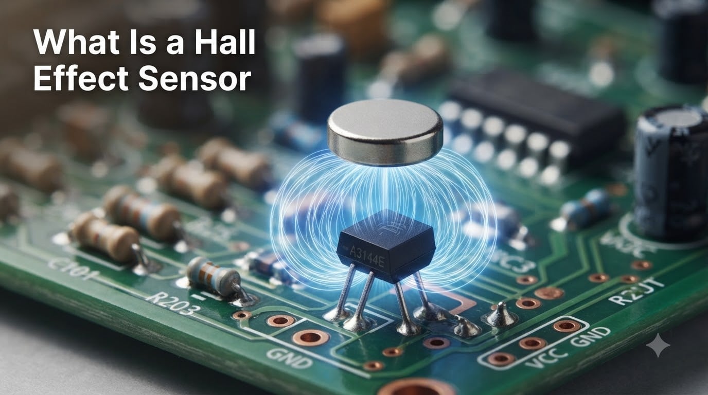
A Hall Effect Sensor is a solid-state magnetic field sensor that detects the presence, strength, and polarity of a magnetic field and converts it into a measurable electrical signal. Because the sensor has no moving parts and never physically touches the magnet, it can run for billions of cycles without wearing out.
In this guide, I will walk you through what a Hall Effect Sensor is, how the underlying physics actually works, the main types on the market, and where you will find them in everyday electronics. I have spent years designing motor controllers and robotics projects around these devices, and I will share the practical lessons I have learned along the way.
Table of Contents
What Is a Hall Effect Sensor? Definition and Origin
A Hall Effect Sensor is a transducer that varies its output voltage in response to a magnetic field. The device uses a thin strip of semiconductor material through which an electrical current flows. When a magnet approaches the strip, the magnetic field pushes the moving charge carriers to one side, producing a tiny voltage perpendicular to the current. That voltage is the Hall voltage, and it is the signal the sensor reports.
The effect is named after American physicist Edwin Hall, who first observed it in 1879 at Johns Hopkins University. Hall was experimenting with thin gold foil and a strong magnet when he noticed that a small voltage appeared across the conductor at right angles to the current flow. His discovery went largely unused for decades because the signals were too small to measure cheaply. Once semiconductor fabrication matured in the mid-twentieth century, engineers finally had materials sensitive enough to turn Hall’s lab curiosity into a practical sensor.
Today, a Hall Effect Sensor is one of the most widely deployed magnetic sensors in the world. Every modern car has dozens of them, and they sit inside brushless motors, smartphone lids, and gaming controllers. The non-contact design means there is nothing to wear out, which is why they have replaced mechanical switches in so many applications.
How Does a Hall Effect Sensor Work? The Physics Explained
A Hall Effect Sensor works by exploiting the Lorentz force, the same force that deflects electrons in a cathode-ray tube. When a current-carrying conductor sits inside a magnetic field, the field pushes the moving charge carriers sideways. That sideways push separates positive and negative charges, generating a small voltage across the conductor called the Hall voltage.
The Lorentz Force and Charge Deflection
Inside a Hall Effect Sensor, a constant bias current flows through a thin semiconductor plate. Electrons travel in a straight line from one terminal to the other under normal conditions. The moment a magnetic field passes through the plate, each electron feels a sideways force equal to the cross product of its velocity and the magnetic flux density. That force is the Lorentz force, and it pushes the electrons toward one edge of the plate.
As electrons pile up along one edge, the opposite edge becomes positively charged. The separation of charge creates a voltage across the plate that is perpendicular to both the current flow and the magnetic field. That voltage is the Hall voltage, and it is the raw output of the sensor.
The Hall Voltage Formula
The Hall voltage is described by a simple equation:
VH = (RH × I × B) / t
Where RH is the Hall coefficient of the material, I is the current flowing through the plate, B is the magnetic flux density, and t is the thickness of the plate. Because the plate is made as thin as possible, even a modest magnet produces a voltage in the millivolt range that an on-chip amplifier can read.
Step-by-Step Operation
- Step 1 – Bias current applied: A small constant current flows through the Hall plate inside the sensor.
- Step 2 – Magnetic field present: A magnet approaches the sensor, and the magnetic flux lines pass through the plate.
- Step 3 – Lorentz force deflects electrons: The magnetic field pushes the moving electrons sideways by the Lorentz force.
- Step 4 – Hall voltage appears: A measurable voltage appears across the plate perpendicular to the current.
- Step 5 – Signal conditioning: The on-chip amplifier and Schmitt trigger convert the tiny voltage into a clean digital or analog output.
Types of Hall Effect Sensors: Digital, Linear, Bipolar, and Unipolar
Not all Hall Effect Sensors behave the same way. Engineers choose between digital and linear outputs, and between bipolar and unipolar switching behavior, depending on what they are sensing. Picking the wrong type is one of the most common mistakes I see in hobby projects.
Digital Hall Effect Sensors (Switch Output)
A digital Hall Effect Sensor behaves like a solid-state switch. The output is either on or off, with no intermediate states. When the magnetic field exceeds a set threshold, the output pulls low (or high, depending on the part). A Schmitt trigger inside the chip cleans up the signal so it does not chatter near the switching point.
Digital Hall Effect Sensors are the workhorses of the sensor world. You will find them in laptop lid-close detection, door sensors in security systems, and cam position sensors in engines.
Linear Hall Effect Sensors (Analog Output)
A linear Hall Effect Sensor produces an analog output voltage that is proportional to the strength of the magnetic field. Instead of just on or off, the output swings across a range (often 0.5 V to 4.5 V on a 5 V supply). This makes linear Hall Effect Sensors ideal for current sensing, throttle position feedback, and contactless joysticks.
Most gaming controller joysticks that have replaced traditional potentiometers use a linear Hall Effect Sensor. A small magnet on the end of the joystick moves relative to the sensor, and the output voltage changes with stick position.
Bipolar vs Unipolar Sensors
The terms bipolar and unipolar describe the magnetic field behavior the sensor responds to.
- Unipolar Hall Effect Sensor: Responds to only one magnetic pole (usually the south pole). It switches on when the south pole approaches and off when the magnet moves away. Simpler circuits use unipolar parts.
- Bipolar Hall Effect Sensor: Responds to both north and south poles. It switches on for one polarity and off for the opposite, which is useful for direction detection in motor commutation and incremental encoders.
Latching Hall Sensors
A latching Hall Effect Sensor is a special digital variant. It latches its output on when it sees a south pole, and only releases the latch when it sees a north pole. This is the classic sensor used inside brushless DC motor controllers, where three latching sensors in a 120-degree arrangement tell the controller which phase to energize next.
Materials Used in Hall Effect Sensors
The material inside a Hall Effect Sensor matters a lot. Early sensors used germanium, but modern designs rely on compound semiconductors that produce a much larger Hall voltage per unit of magnetic field.
- Indium antimonide (InSb): Very high electron mobility, so it produces a strong signal. The downside is temperature sensitivity, which limits its use to laboratory or controlled environments.
- Gallium arsenide (GaAs): A good balance of sensitivity and low temperature drift, which is why you will see it in many precision industrial sensors.
- Silicon (Si): Lower sensitivity than the compound semiconductors, but silicon is cheap and easy to integrate with on-chip amplifiers. The vast majority of modern Hall Effect Sensors are silicon-based.
- Indium arsenide (InAs): Used in thin-film Hall Effect Sensors where very high sensitivity and small size are required.
Choosing the right material is part art, part science. For most hobby work, silicon is perfectly fine. For industrial current sensing, designers lean toward GaAs or InAs for the extra precision.
Detection Modes: Head-On and Sideways
A Hall Effect Sensor can detect a magnet in two basic ways, and the detection mode changes how the output responds to motion.
In head-on detection, the magnet moves directly toward and away from the face of the sensor. As the magnet gets closer, the field strength at the sensor increases, and the output rises. When the magnet retreats, the field drops and the output falls. This mode is the most sensitive and is used for short-range position detection.
In sideways detection, the magnet slides across the front of the sensor along its face. The field at the sensor changes from one polarity to the other as the magnet passes by. Bipolar and latching Hall Effect Sensors are commonly deployed this way in wheel-speed sensors and flow meters, where a rotating multipole ring or impeller creates a toggling field.
Common Applications of Hall Effect Sensors
What does a Hall Effect Sensor detect in the real world? Almost anything magnetic. Below are the most common application categories I have run into across automotive, industrial, and consumer projects.
Automotive Applications
Modern vehicles are the single largest market for Hall Effect Sensors. A typical car uses 20 or more of them in functions such as:
- Crankshaft and camshaft position sensing for ignition timing
- Wheel speed detection for anti-lock braking systems (ABS)
- Throttle position feedback for engine control units
- Seat belt buckle detection and seat position memory
- Steering angle sensing for electronic stability control
Industrial and Motor Control
In industrial settings, Hall Effect Sensors serve as brushless DC motor commutation sensors, where three latching devices determine rotor position. They also act as end-of-travel limit switches on pneumatic cylinders, where a magnet on the piston tells the controller it has reached the end of its stroke.
Consumer Electronics and Gaming
Hall Effect Sensors have quietly replaced mechanical switches in many consumer products. The latest game controllers, including the premium versions of popular console pads, use linear Hall Effect Sensors in their joysticks to eliminate stick drift. Laptops use them to detect when the lid is closed, and smartphones use them to detect accessory attachment.
Current Sensing and Robotics
Hall Effect current sensors clamp around a conductor and use the magnetic field produced by the current to measure it without breaking the circuit. Robotics engineers also use them as contactless rotary encoders, attaching a small diametrically magnetized magnet to a motor shaft and reading its angle with a 3D Hall Effect Sensor.
Advantages and Limitations of Hall Effect Sensors
Hall Effect Sensors bring real benefits to the table, but they are not the right tool for every job. Knowing the limits is just as important as knowing the strengths.
Advantages
- Non-contact operation: No mechanical wear, so the sensor can run for billions of cycles.
- Solid-state reliability: No moving parts means resistance to shock and vibration.
- High switching speed: Digital outputs can toggle in microseconds, which is fast enough for motor commutation at high RPM.
- Wide temperature range: Automotive-grade parts routinely operate from -40 degrees C to 150 degrees C.
- Low cost: Mass-produced Hall Effect Sensors cost a few cents each in volume.
Limitations
- Limited range: Useful sensing distance is usually a few millimeters to a few centimeters, depending on magnet strength.
- Susceptible to external magnetic fields: Strong stray fields from motors or power cables can cause false triggers if the design is not shielded.
- Temperature drift: The Hall coefficient changes slightly with temperature, which can shift switching thresholds or analog baselines.
- Requires a magnet: Unlike inductive or capacitive sensors, the target itself must be magnetic, or a magnet must be attached to it.
How to Test a Hall Effect Sensor with a Multimeter
One of the most common questions I see in forums is how to tell whether a Hall Effect Sensor has failed. A basic digital multimeter can give you a quick answer in a few minutes.
For a 3-wire Hall Effect Sensor (power, ground, output), start by identifying the three pins. Most sensors follow the same convention when you look at the flat face with the print facing you: ground on the left, power in the middle, output on the right. Check the datasheet to be sure.
Set your multimeter to DC voltage and connect the black lead to ground. With the sensor powered, measure the output voltage with no magnet nearby. A digital sensor should read either close to the supply voltage or close to ground, depending on its active state. A linear sensor should read somewhere in the middle of its output range.
Now bring a magnet close to the face of the sensor. The output should change. If you have a digital unipolar sensor, the output should toggle when the south pole approaches. If nothing changes, the sensor is likely dead. If the output is stuck at one rail regardless of the magnet, the internal amplifier is probably shorted.
For a 2-wire Hall Effect Sensor, the test is similar, but you measure current draw instead of output voltage. The sensor switches between a low and high current state, and your multimeter in series with the supply should show a clear difference when the magnet moves in and out.
Hall Effect Sensor vs Reed Switch: How They Compare
A reed switch is the closest mechanical cousin of the Hall Effect Sensor, and engineers often pick between the two. A reed switch is a pair of ferromagnetic contacts sealed inside a glass tube. When a magnet approaches, the contacts pull together and close the circuit. When the magnet moves away, a spring pulls them apart.
A Hall Effect Sensor does the same job electronically, with no moving parts. That single difference has a cascade of consequences:
- Lifespan: A reed switch is rated for millions of cycles, while a Hall Effect Sensor can handle billions.
- Bounce: A reed switch contacts physically, so it bounces. A Hall Effect Sensor output is clean.
- Vibration resistance: A reed switch can false-trigger under heavy vibration. A solid-state Hall Effect Sensor ignores vibration completely.
- Size: Modern Hall Effect Sensors come in SMD packages smaller than a grain of rice. Reed switches are still relatively bulky.
The reed switch still has a niche where it wins: its contacts can switch mains voltage directly, and it draws zero quiescent current. For battery-powered devices, however, the Hall Effect Sensor is almost always the better pick.
Frequently Asked Questions
What is Hall effect in simple words?
The Hall effect is the creation of a small voltage across an electrical conductor when a magnetic field passes through it. A Hall Effect Sensor uses this voltage to detect magnets and convert them into an electrical signal a circuit can read.
What are the downsides of Hall Effect sensors?
Hall Effect Sensors have a limited sensing range of a few millimeters to centimeters, can be fooled by stray magnetic fields, drift slightly with temperature, and only work when a magnet or magnetic target is present.
Can a Hall Effect sensor be used as a switch?
Yes. A digital Hall Effect Sensor acts exactly like a solid-state switch. Its output goes on or off when a magnetic field crosses a threshold, and it can drive a transistor, microcontroller input, or relay coil directly.
Why do Hall Effect sensors fail?
The most common failure causes are heat damage in automotive under-hood environments, mechanical stress on the package, moisture or contamination in brushless motor housings, and voltage spikes that fry the on-chip amplifier.
What does a Hall Effect sensor detect?
A Hall Effect Sensor detects the presence, strength, and polarity of a magnetic field. It can measure the position of a magnet, the speed of a rotating ring of magnets, or the current flowing through a wire by sensing the magnetic field around it.
What is the lifespan of a Hall sensor?
A solid-state Hall Effect Sensor has no moving parts, so its lifespan is not limited by mechanical wear. Most sensors are rated for billions of switching cycles and last as long as the device they are installed in, provided they stay within their voltage and temperature ratings.
Final Thoughts on Hall Effect Sensors
A Hall Effect Sensor is one of the most useful and underrated components in modern electronics. It turns invisible magnetic fields into clean electrical signals without ever touching anything, which is why it has replaced mechanical switches in everything from car ignitions to gaming controllers.
If you are designing a new project, start by asking whether your target is magnetic or whether you can attach a small magnet to it. If yes, a Hall Effect Sensor will give you reliable, long-life sensing that other technologies struggle to match. Pick digital for on/off detection, linear for proportional measurement, and bipolar or latching when you need to detect direction or rotation. And if something stops working, your multimeter is usually enough to diagnose the failure in a few minutes.
I hope this guide has given you a clear picture of what a Hall Effect Sensor is, how it works, and where to use one. The technology has been around for nearly 150 years, and it is still finding new applications every year.