
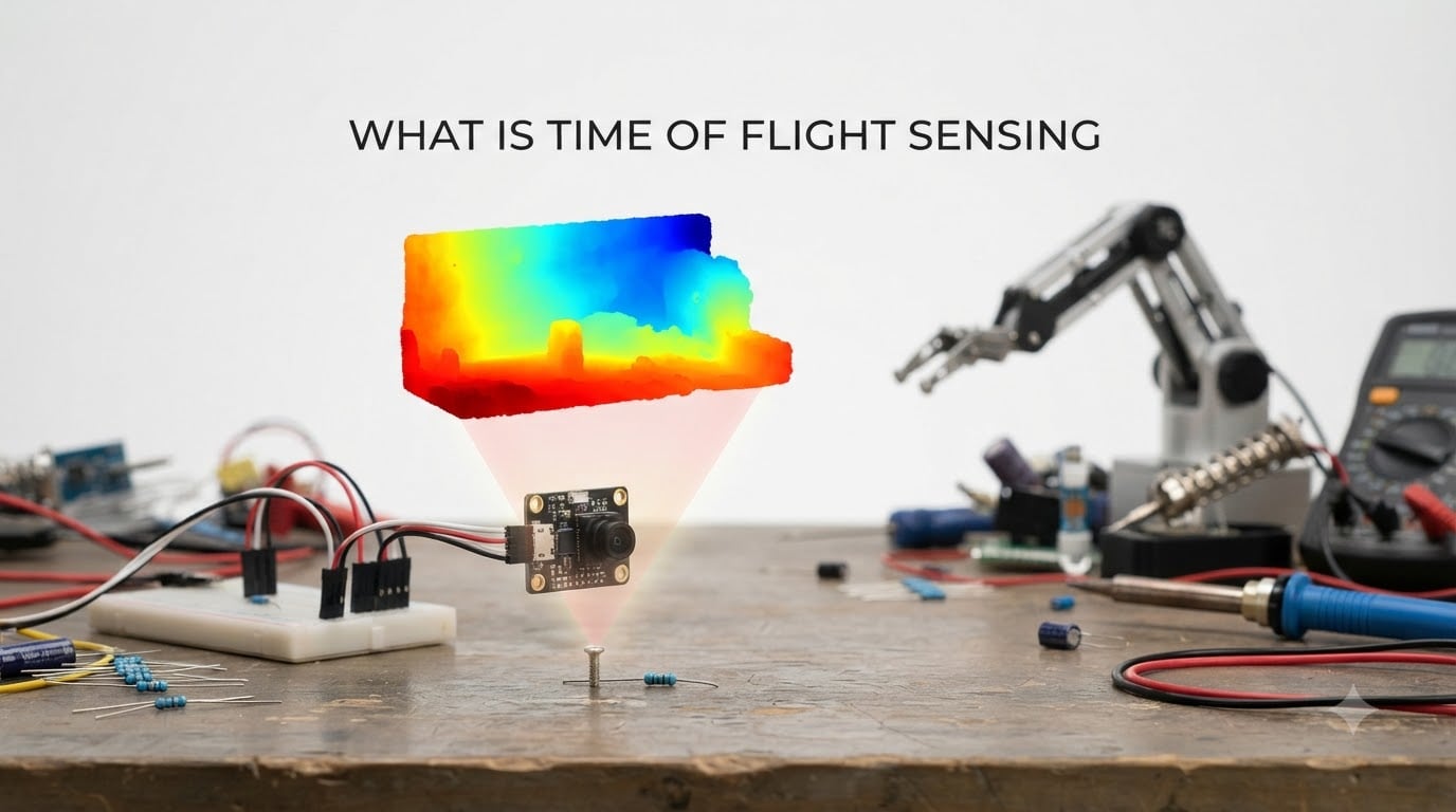
If you have ever wondered how a robot vacuum senses the leg of a chair in milliseconds, how a modern phone blurs the background in portrait mode, or how a car nudges the brakes before you do, you are looking at Time of Flight sensing at work. I have spent the last several years working with ToF modules on drones, AGVs, and gesture interfaces, and I keep coming back to the same simple idea: light moves at a known speed, so measuring how long a pulse takes to come back tells you exactly how far away something is.
Time of Flight sensing, often shortened to ToF, is a non-contact distance-measurement method that uses a pulse or wave of light to map the world in three dimensions. In this guide I will walk you through what Time of Flight sensing is, how the underlying physics turns into millimeter-level depth maps, the different types of ToF sensors you will meet, where the technology shines, where it falls short, and how you can start using it on your own projects.
Table of Contents
What Is Time of Flight Sensing?
Time of Flight sensing is a range imaging technique that measures the distance between a sensor and an object by timing how long an emitted light signal takes to travel to the target and return. Because light moves at roughly 299,792,458 meters per second, even a one-millimeter change in distance shifts the round-trip time by about 6.7 picoseconds, which is the order of precision modern ToF sensors are built to resolve.
A ToF sensor is essentially a range imaging camera system. It packages a light source, usually an infrared laser or LED, with a specialized image sensor that records the returning photons. The result is a depth map where every pixel carries a distance value, not just a brightness value, which is what separates ToF from a regular camera.
Two phrases you will see used interchangeably are ToF sensor and ToF camera. They refer to the same principle, although in practice a ToF camera tends to mean a 2D focal plane array that produces a full depth image, while a ToF sensor often refers to a single-point or multi-zone module that reports distances for one or a small grid of pixels.
How Time of Flight Sensing Works
Time of Flight sensing works by sending out a light signal, watching for the reflection, and converting the round-trip travel time into a distance using the speed of light. The math is the same equation taught in introductory physics: distance equals speed multiplied by time, divided by two because the light makes a round trip.
The basic formula used in every ToF system is:
Distance = (Speed of Light x Time of Flight) / 2
Walking through the process step by step, here is what happens inside a ToF sensor on every measurement cycle:
- The emitter, usually a vertical-cavity surface-emitting laser (VCSEL) at 850 nm or 940 nm, fires a short, modulated pulse of infrared light toward the scene.
- The light hits objects in the field of view and a portion of it scatters back toward the sensor.
- A focal plane array of photodiodes, each tuned to the emitter wavelength, captures the returning photons on every pixel simultaneously.
- Timing electronics, either a high-speed clock for direct ToF or a phase detector for indirect ToF, measure how long the light was gone or how much its phase shifted.
- An on-board processor applies the distance formula to the timing data and outputs a depth value per pixel, often 30 to 60 times per second.
The clever part is that the entire array captures depth in a single shot, which is why ToF is called single-shot 3D imaging. There is no scanning mirror, no mechanical part, and no need to move the sensor to build up a depth map. I have used ToF modules in vibrating drone mounts where scanning LiDAR would smear, and the ToF data stayed sharp.
Types of ToF Sensors: Direct vs Indirect ToF
ToF sensors come in two main flavors, plus a third hybrid approach used in some industrial systems. The distinction comes down to how the round-trip time is actually measured.
Direct Time of Flight (dToF)
Direct ToF sensors emit very short laser pulses, often under a nanosecond, and use a fast stopwatch to time each one. The measurement is essentially the textbook application of the distance formula. Single-photon avalanche diodes (SPADs) are commonly used as the receivers because they can register individual photons with timing precision in the tens of picoseconds.
Direct ToF handles long ranges well, is more robust to ambient light, and scales gracefully to high resolution, which is why automotive LiDAR modules and the latest smartphone focus systems tend to favor it. The trade-off is that the supporting electronics are more complex and historically more expensive.
Indirect Time of Flight (iToF)
Indirect ToF sensors shine a continuously modulated light wave, often in the 10 to 100 MHz range, and measure the phase shift between the emitted and reflected signals. Phase shift and time of flight are directly related: a 90-degree phase shift at 20 MHz corresponds to about 3.75 nanoseconds of delay, which translates to roughly 0.56 meters of distance.
Indirect ToF uses cheaper CMOS pixels and is easier to mass-produce, which is why you will find it in most consumer devices, from robot vacuums to gesture-recognition modules. The downside is a shorter unambiguous range, usually a few meters, and more sensitivity to multi-path reflections from shiny or concave surfaces.
Range-Gated Imagers
Range-gated ToF imagers work like a shutter, opening the sensor’s exposure only for a brief window that corresponds to a specific distance slice. By stepping the window through time, the system builds up a depth map. This approach is common in military and traffic-speed applications where long range and strong sunlight rejection are required.
Key Components Inside a ToF Sensor
Every ToF sensor, regardless of type, shares a similar set of building blocks. Knowing what each piece does makes troubleshooting and integration much easier.
- Illumination source: A VCSEL laser or modulated LED that emits at a wavelength the matching sensor is designed to receive, typically 850 nm or 940 nm.
- Lenses: Both emitter and receiver optics shape the field of view and focus returning light onto the pixel array.
- Sensor pixel array: A focal plane array of photodiodes or SPADs, each producing a timing or phase signal.
- Timing electronics: High-speed clocks, phase detectors, or time-to-digital converters that turn the optical signal into a measurable quantity.
- Processor and interface: A small MCU or ASIC that calculates depth, applies calibration, and exposes the result over I2C, SPI, USB, or MIPI.
Advantages of Time of Flight Sensing
ToF became popular because it solves a lot of problems that older distance sensors could not. The main advantages I lean on when I recommend a ToF module for a new project are speed, simplicity, and depth data density.
- Real-time depth at high frame rate: Most ToF sensors run at 30 to 60 frames per second, fast enough for closed-loop robot control and gesture tracking without buffering.
- Single-shot 3D imaging: Each frame is a full depth image, so the system does not need a scanning mechanism or a moving sensor head.
- Compact and lightweight: A typical VL53L5CX board measures around 18 by 11 millimeters and weighs a few grams, which is why drones and phones can carry them.
- Low power consumption: Modules like the ST VL53L0X draw single-digit milliamps during ranging, which makes them practical for battery-powered projects.
- Millimeter accuracy at short range: Indirect ToF modules routinely hit plus or minus 1 to 3 percent accuracy from a few centimeters up to a couple of meters.
- Works in darkness: Because the sensor provides its own illumination, ToF operates the same way whether the lights are on or off.
Disadvantages and Limitations of ToF Sensors
No sensor is perfect, and Time of Flight sensing has well-known weak spots that I have run into more than once. Being aware of them up front saves a lot of debugging time.
- Background light interference: Strong sunlight or other IR sources can swamp the sensor’s own illumination, reducing range and accuracy. Filtering and shorter exposures help but do not eliminate the problem.
- Multi-path reflections: Light bouncing off multiple surfaces before returning can cause the reported distance to drift toward the longest path. Concave shapes, mirrors, and shiny metal are typical troublemakers.
- Limited range: Indirect ToF modules usually top out around 2 to 4 meters for reliable data. Direct ToF and range-gated imagers reach much farther, but at higher cost and complexity.
- Minimum distance: Many ToF sensors, including the popular VL53L0X, have a minimum range of about 30 millimeters. Hitting objects closer than that often returns a timeout or wrong reading.
- Cross-talk between sensors: Place two identical ToF modules facing each other and you may see interference as each one picks up the other’s pulse. Staggered timing or different modulation frequencies are the standard fixes.
- Lower spatial resolution than stereo cameras: A typical ToF camera outputs QVGA (320 by 240) depth pixels or less, while a stereo rig can deliver matching RGB resolution.
ToF vs LiDAR vs Ultrasonic: How They Compare
One of the questions I get most often is how Time of Flight sensing compares to LiDAR and ultrasonic ranging, so I put together a quick side-by-side. The short version is that they overlap, but each one has a sweet spot.
| Feature | Time of Flight (ToF) | LiDAR | Ultrasonic |
|---|---|---|---|
| Signal type | Infrared light pulse or modulated wave | Laser pulse, usually 905 nm or 1550 nm | Acoustic pulse, typically 40 kHz |
| Typical range | A few centimeters to about 10 m (consumer), 100+ m (specialized) | 10 m to 250+ m | A few centimeters to about 10 m |
| Accuracy | Millimeter-level at short range | Centimeter-level at long range | Centimeter-level, often plus or minus 1 to 3 cm |
| Field of view | Wide, full 2D depth image in one shot | Narrow unless scanning, often 1D or 2D scanning | Narrow cone, single point per measurement |
| Cost | Low to moderate for consumer modules | High, especially for long-range automotive units | Very low, a few dollars per transducer |
| Strengths | Compact, low power, fast 3D data | Long range, excellent for outdoor mapping | Inexpensive, ignores color and transparency |
| Weaknesses | Background light, multi-path issues | Bulky, expensive, moving parts on some units | Slow, narrow beam, soft surfaces absorb sound |
In practice, ToF and LiDAR are close cousins that both rely on the time-of-flight principle. LiDAR usually refers to longer-range, scanning systems, while ToF generally describes the compact, solid-state modules that have become common in phones and robots. Ultrasonic is the budget option that still does a great job on simple tasks like bin-level detection.
Real-World Applications of ToF Sensing
Time of Flight sensing shows up in more places than most people realize. Here are the use cases I see most often as a robotics engineer.
Robotics and Autonomous Navigation
Robot vacuums, AGVs, and warehouse robots all use ToF arrays to detect obstacles and walls. The data feeds directly into a real-time operating system in robotics for predictable motion control. I have used the VL53L1X on small rovers where the 3 to 400 centimeter range was perfect for indoor mapping.
Automotive Safety Systems
Modern cars use direct ToF modules for driver monitoring, gesture-controlled infotainment, and short-range parking assist. Long-range automotive LiDAR is a specialized form of ToF that uses the same time-of-flight principle to detect objects 200 meters or more away.
Smartphone Cameras and AR
Phone makers use ToF cameras for autofocus assist, portrait-mode depth effects, and AR scene understanding. The result is faster focus in low light and more accurate background separation than a pure software approach.
Industrial Automation and Machine Vision
Factories deploy ToF cameras to check the volume of packages on a conveyor, monitor fill levels in bins, and verify the presence of parts on an assembly line. The millimeter accuracy and high frame rate are ideal for inline quality control.
Gesture Control and Gaming
Gaming peripherals, AR headsets, and smart-home panels use ToF to track hand position and gestures without the user touching anything. The low latency makes interactions feel natural.
Traffic and Crowd Monitoring
Range-gated ToF imagers mounted above roads measure vehicle speed and classify vehicles by profile. They also help count people in spaces while preserving anonymity, since no identifying image is stored.
Are ToF Sensors Safe for Eyes?
Yes, the vast majority of consumer and industrial ToF sensors are eye-safe under normal use. Most off-the-shelf modules, including the ST VL53L0X, VL53L1X, and VL53L5CX families, are classified as Class 1 laser products, which means the accessible emission limit is below the level known to cause eye damage even with continuous exposure.
A few caveats are worth keeping in mind. Do not look directly into a ToF emitter at close range for extended periods, and avoid staring into the lens with optical aids like binoculars. If you are building a custom system with a higher-power laser, follow the IEC 60825-1 standard and add the appropriate warning labels. In short, treat the emitter like a bright LED, not a cutting laser, and you are well within safe limits.
Getting Started with ToF: Arduino and Hobbyist Projects
The fastest way to get hands-on with Time of Flight sensing is to pick up one of the popular breakout boards and wire it to a microcontroller. The ST VL53L0X and VL53L1X are the go-to choices for single-point ranging, and the VL53L5CX adds a 4×4 or 8×8 multi-zone depth map for more advanced projects.
A typical first project looks like this:
- Connect the sensor to an Arduino, ESP32, or Raspberry Pi over I2C. The wiring is just VCC, GND, SDA, and SCL.
- Install the manufacturer’s library. Pololu, Adafruit, and ST all publish well-maintained Arduino libraries.
- Open the example sketch, set the measurement mode to single-shot or continuous, and print the distance in millimeters over the serial monitor.
- Use the readings to trigger a buzzer when an object comes within 100 millimeters, or feed them into a ROS 2 node for a small robot.
For robotics obstacle avoidance, I usually recommend the VL53L1X because it handles the 3 to 400 centimeter range that indoor rovers actually need. For multi-zone work like a low-resolution depth camera, the VL53L5CX is hard to beat, and it is supported on ESP32 and Raspberry Pi Pico out of the box.
If you run into timeout errors, double-check that the sensor is not facing another active ToF module without staggered timing, and try adding a short delay between measurements to let the photodiode array recover from bright ambient light.
Frequently Asked Questions
Is time-of-flight the same as LiDAR?
Both use the time-of-flight principle of measuring how long a light pulse takes to return, but the term LiDAR usually refers to long-range scanning systems, while ToF typically describes compact, solid-state modules that produce a depth image in a single shot without moving parts.
What are the disadvantages of ToF sensors?
ToF sensors can suffer from background light interference, multi-path reflections from shiny surfaces, a limited measurement range, cross-talk between adjacent sensors, and a minimum sensing distance of a few centimeters on most consumer modules.
How does time-of-flight work?
A ToF sensor emits a pulse or modulated wave of infrared light, records the returning photons on a pixel array, and converts the round-trip travel time, or the equivalent phase shift, into a distance using the speed of light, then outputs a depth value for every pixel in a single frame.
Are ToF sensors safe for eyes?
Most consumer and industrial ToF sensors, including the popular VL53L0X and VL53L1X families, are Class 1 laser products that are safe under normal use, though you should avoid staring into the emitter at close range and follow IEC 60825-1 guidance for custom high-power designs.
How accurate is a time of flight sensor?
Indirect ToF modules typically deliver plus or minus 1 to 3 percent accuracy at distances from a few centimeters up to 2 meters, which works out to a few millimeters in most cases, while direct ToF and specialized range-gated imagers can reach sub-millimeter precision in controlled conditions.
What is the minimum distance of a ToF sensor?
Most consumer ToF modules have a minimum measurement distance of about 30 millimeters because the timing electronics need a short blanking period between the emitted pulse and the receiver opening; closer objects usually produce a timeout or an invalid reading.
Can ToF sensors work in sunlight?
Yes, but with reduced range and accuracy. Strong ambient infrared light, especially sunlight, raises the noise floor on the photodiode array, so most ToF modules use optical bandpass filters and shorter integration times to keep working outdoors, though heavy direct sun can still swamp the signal.
Final Thoughts on Time of Flight Sensing
Time of Flight sensing is one of those rare technologies that bridges robotics research, consumer electronics, and hobbyist work without forcing a trade-off between price and performance. In 2026 it is showing up in everything from phone cameras to autonomous vehicles, and modules like the VL53L1X have made it easy to add real depth perception to a 30 dollar robot.
If you are starting a new project, decide on your required range first, then choose between direct ToF for long-range, high-accuracy work and indirect ToF for compact, low-power, short-range sensing. Pay attention to ambient light, surface reflectivity, and minimum distance, and you will avoid most of the common pitfalls.
Pick up a breakout board, run the example sketch, and start measuring. Once you see a depth map stream in real time, the rest of the project usually writes itself.