
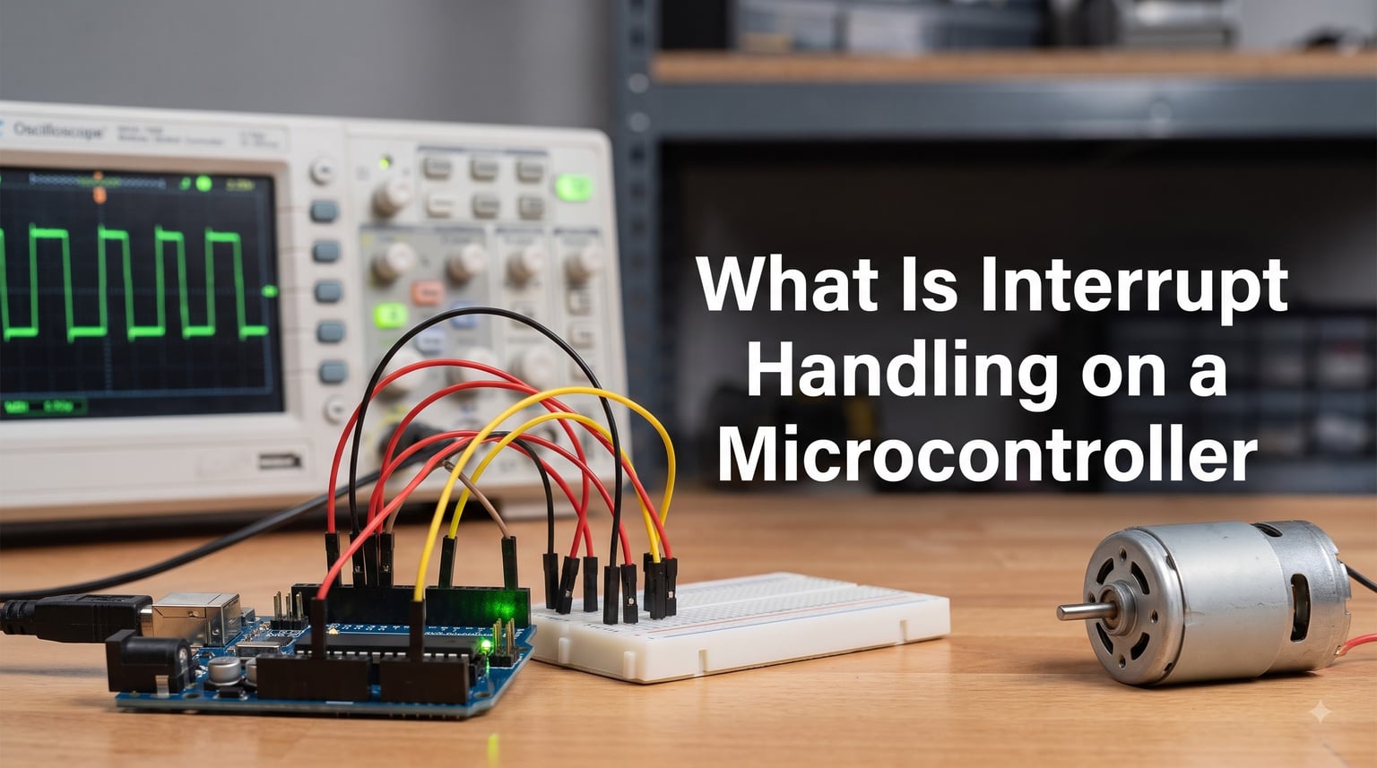
Interrupt handling on a microcontroller is the mechanism that lets the processor pause whatever it is doing, respond immediately to an important event, and then pick up right where it left off. Instead of constantly checking whether something happened, the CPU waits for a signal and reacts only when needed. This approach saves processing time, reduces power consumption, and makes real-time responses possible.
If you are building anything with a microcontroller, from a simple Arduino LED project to a complex microcontroller application in robotics, understanding interrupts is one of the most important skills you can develop. I remember struggling with this concept myself when I first started with embedded systems, so I am going to break it down in plain language.
In this guide, we will cover what interrupt handling on a microcontroller actually means, how the process works step by step, the different types of interrupts you will encounter, and practical examples you can apply to your own projects. We will also address common pitfalls that trip up beginners and experienced developers alike.
Table of Contents
What Are Interrupts in a Microcontroller?
An interrupt is a signal sent to the microcontroller’s CPU telling it that an event needs immediate attention. The signal can come from a hardware source, like a button press or a timer reaching zero, or from software, like a division-by-zero error. When the CPU receives this signal, it stops executing the current program temporarily and runs a special piece of code designed to handle that specific event.
Think of it like reading a book. You are deep into a chapter, and suddenly the phone rings. You put a bookmark on the current page (saving your place), answer the call, deal with whatever the caller needs, and then return to the exact page where you stopped. The phone ring is the interrupt. Answering the call is the interrupt handler. Going back to the book is the return from interrupt.
This analogy maps directly to how microcontrollers work. The “bookmark” is the CPU saving its current state to memory (specifically, the program counter and relevant registers onto the stack). The “answering the call” is executing the Interrupt Service Routine. The “returning to the page” is restoring the saved state and resuming the main program.
Without interrupts, a microcontroller would have to constantly check every possible event source in a loop, asking “did anything happen yet?” over and over. This technique is called polling, and while it works for simple tasks, it wastes enormous amounts of processing power. Interrupts flip this model entirely, making the microcontroller event-driven rather than check-driven.
Here are the key terms you will encounter throughout this article:
Interrupt Request (IRQ): The actual signal that triggers the interrupt. It can be a physical pin changing voltage or an internal peripheral flag being set.
Interrupt Vector: A memory address that tells the CPU where to find the ISR for a specific interrupt source.
Interrupt Flag: A bit in a special register that gets set when an interrupt event occurs. The CPU checks this flag to know which interrupt fired.
Interrupt Enable: A configuration bit that allows or blocks a specific interrupt. You must enable an interrupt before the CPU will respond to it.
How Interrupts Work: Step by Step
Understanding how interrupt handling works on a microcontroller requires following the sequence of events from trigger to return. Let me walk you through each stage, because this is one of the most common questions beginners ask on forums like r/embedded.
Step 1: An Event Occurs
Something physical or internal triggers an interrupt. This could be a button press on an external pin, a timer reaching its maximum count, a UART module receiving a byte of serial data, or an analog-to-digital converter finishing a conversion. The peripheral hardware sets the corresponding interrupt flag in its status register.
Step 2: The Interrupt Controller Processes the Request
Most modern microcontrollers have a dedicated interrupt controller (like the Nested Vectored Interrupt Controller, or NVIC, on ARM Cortex-M chips). This controller receives all interrupt requests, checks which ones are enabled, and determines priority if multiple interrupts fire at the same time. It then sends a single consolidated signal to the CPU core.
Step 3: The CPU Finishes the Current Instruction
The CPU does not stop mid-instruction. It completes whatever single instruction it is currently executing. This is important because microcontroller instructions are atomic, meaning they cannot be split. Once the current instruction finishes, the CPU is ready to be diverted.
Step 4: Context Saving
The CPU automatically saves its current state so it can return later. It pushes the program counter (the address of the next instruction it was about to execute) onto the stack. On some architectures, it also saves other registers automatically. The compiler handles saving any additional registers the ISR might modify, so you do not have to worry about this manually in most cases.
Step 5: Jumping to the ISR via the Vector Table
The CPU looks up the interrupt vector table, a predefined list of memory addresses where each entry corresponds to a specific interrupt source. The table entry for the fired interrupt contains the address of its ISR. The CPU loads that address into the program counter, effectively jumping to the ISR code.
Step 6: Executing the Interrupt Service Routine
The ISR runs. This is the code you write to handle the event. It might read a sensor value, toggle an LED, store received data in a buffer, or set a flag for the main loop to process. The ISR should be as short and fast as possible. We will cover why in detail later.
Step 7: Clearing the Interrupt Flag
Before returning, the ISR must clear the interrupt flag that triggered it. If you forget this step, the CPU will immediately re-enter the ISR as soon as it returns, creating an infinite loop that freezes your program. This is one of the most common bugs beginners encounter.
Step 8: Return from Interrupt
The ISR ends with a special return instruction (like RETI on AVR or BX LR on ARM). The CPU pops the saved program counter and registers back from the stack, restoring its previous state. Execution resumes at the exact point where the interrupt occurred, as if nothing happened.
The entire process from interrupt trigger to ISR execution typically takes just a few microseconds. On an AVR microcontroller running at 16 MHz, the response time is around 3 to 4 microseconds. Faster ARM Cortex-M chips can respond in under 200 nanoseconds. This speed is what makes interrupt handling essential for time-critical applications.
Types of Interrupts in Microcontrollers
Microcontrollers categorize interrupts in several ways, and understanding these categories helps you choose the right interrupt type for your application. The four main classifications are hardware versus software, external versus internal, edge-triggered versus level-triggered, and by source (timer, external, serial).
Hardware Interrupts vs Software Interrupts
Hardware interrupts come from physical signals or internal peripherals. A GPIO pin changing state, a timer overflowing, or a UART receiving data are all hardware interrupts. These are the most common type you will work with in embedded projects.
Software interrupts are triggered by the program itself, usually through a special instruction. On ARM, the SVC (Supervisor Call) instruction generates a software interrupt. These are often used for operating system calls or to deliberately trigger exception handlers. Fault conditions like division by zero or invalid memory access also generate software interrupts, sometimes called traps or exceptions.
External Interrupts vs Internal Interrupts
External interrupts are triggered by signals on specific microcontroller pins. These are the interrupts you use for things like button presses, rotary encoders, or external sensor alerts. Most microcontrollers dedicate a handful of GPIO pins as external interrupt sources. On Arduino boards, pins 2 and 3 on the Uno support external interrupts.
Internal interrupts come from on-chip peripherals. Timer overflows, analog-to-digital conversion completions, UART receive buffer full, SPI transfer complete, and watchdog timer expiry are all internal interrupts. Every peripheral on the microcontroller typically has at least one associated interrupt.
Edge-Triggered vs Level-Triggered Interrupts
External interrupts can be configured to trigger on edges or levels. An edge-triggered interrupt fires when a pin transitions from one state to another. You can choose rising edge (low to high), falling edge (high to low), or both. Edge triggering is ideal for detecting discrete events like button presses.
A level-triggered interrupt fires continuously as long as the pin remains in a specific state (high or low). This is useful when you need to monitor an ongoing condition, but it requires you to resolve the condition before returning from the ISR. Otherwise, the interrupt keeps re-firing.
Interrupts by Source
Most microcontrollers provide these common interrupt sources:
Timer Interrupts: Fire when a hardware timer reaches a specific count. Used for precise timing, generating periodic events, or creating PWM signals. Timer interrupts are the backbone of task scheduling in embedded systems.
External Pin Interrupts: Fire when a configured external pin changes state. Used for user input, emergency stop buttons, and external signal detection.
Serial Communication Interrupts: Fire when UART, SPI, or I2C peripherals send or receive data. Essential for handling communication without blocking the main program.
Analog Interrupts: Fire when an analog-to-digital conversion completes or when an analog comparator detects a threshold crossing.
Watchdog Timer Interrupt: Fires (or resets the chip) if the main program stops responding. This is a safety mechanism that catches software hangs. Understanding these reset behaviors is related to broader microcontroller reset issues and system stability.
The Interrupt Service Routine (ISR) Explained
The Interrupt Service Routine is the function that runs when an interrupt fires. It is the core of interrupt handling on a microcontroller. Everything you want to happen in response to an event goes inside the ISR. But writing a good ISR requires discipline, because poorly designed ISRs cause some of the hardest bugs to track down.
Here is a simple Arduino example showing an ISR that toggles an LED when a button is pressed on pin 2:
const int ledPin = 13;
volatile bool buttonPressed = false;

void setup() {
  pinMode(ledPin, OUTPUT);
  pinMode(2, INPUT_PULLUP);
  attachInterrupt(digitalPinToInterrupt(2), buttonISR, FALLING);
}

void loop() {
  if (buttonPressed) {
    digitalWrite(ledPin, !digitalRead(ledPin));
    buttonPressed = false;
  }
}

void buttonISR() {
  buttonPressed = true;
}
Notice that the ISR does almost nothing. It just sets a flag. The main loop checks the flag and does the actual work. This pattern is intentional and is considered a best practice.
The Golden Rule: Keep ISRs Short
The single most important rule of ISR design is to keep them short and fast. An ISR should take microseconds, not milliseconds. When the CPU is inside an ISR, it cannot execute the main program. If your ISR takes too long, the main program appears frozen, timing-sensitive code breaks, and other interrupts may be missed.
Forum users on r/embedded frequently share stories of mysterious system freezes traced back to ISRs containing long-running code. One common mistake is calling Serial.print() inside an ISR. Serial communication is slow, and calling it from an ISR can block the system for hundreds of microseconds or more.
Instead of doing heavy work in the ISR, set a flag and let the main loop handle it. This is called the “deferred processing” pattern. The ISR captures the event quickly, and the main loop processes it when it has time.
The Volatile Keyword: Why It Matters
Variables shared between an ISR and the main program must be declared with the volatile keyword. This is not optional. Without it, the compiler may optimize away reads of the variable in the main loop because it does not know the ISR can change it at any time.
In the example above, buttonPressed is declared volatile. This tells the compiler to always read the variable from memory instead of caching it in a CPU register. If you forget volatile, your program may work in testing but fail unpredictably in production, because the compiler optimization depends on the surrounding code.
This is one of the most frequent sources of confusion for beginners. The variable looks correct, the logic looks correct, but the program still does not work because the compiler is hiding changes from the main loop.
Atomic Operations and Critical Sections
When you share multi-byte variables between an ISR and main code, a new problem emerges. The CPU can be interrupted in the middle of reading or writing a 16-bit or 32-bit variable. The ISR modifies part of the variable, and the main code reads a corrupted value.
To prevent this, you need to protect shared variables with critical sections. A critical section temporarily disables interrupts, performs the read or write, and then re-enables interrupts. On Arduino, you can use noInterrupts() and interrupts() for this purpose:
noInterrupts();
uint16_t safeCopy = sharedCounter;
interrupts();
// Use safeCopy safely
Keep critical sections as short as possible, since disabling interrupts means the CPU will miss any events that occur during that window.
Interrupts vs Polling: Which Should You Use?
Polling and interrupt-driven approaches solve the same problem differently. With polling, the main loop continuously checks whether an event occurred. With interrupts, the CPU is notified only when the event happens. Each approach has trade-offs, and the right choice depends on your specific application.
Here is a comparison of the two approaches:
Responsiveness: Interrupts respond in microseconds because the hardware handles detection. Polling only detects events when the check loop reaches that input, which can introduce significant delay if the loop is busy.
CPU Efficiency: Interrupts free the CPU for other work or let it sleep in a low-power mode between events. Polling keeps the CPU busy constantly, burning power even when nothing is happening.
Code Complexity: Polling is simpler to write and debug. You have full control over execution order, and there are no concurrency issues. Interrupts add complexity through shared variables, volatile keywords, and race conditions.
Predictability: Polling is deterministic. The same code runs in the same order every time. Interrupts are asynchronous, meaning they can fire at any point in your main loop, making timing harder to predict.
Polling works best when: Events happen frequently, you need to check many inputs simultaneously, timing precision is not critical, or the system is simple enough that constant checking is acceptable.
Interrupts work best when: Events are infrequent or unpredictable, you need immediate response, power consumption matters, or the CPU needs to handle multiple tasks concurrently.
Many experienced developers use a hybrid approach. Interrupts handle time-critical events, while polling manages less urgent inputs in the main loop. This gives you the responsiveness of interrupts without the complexity of making everything interrupt-driven.
Practical Applications of Interrupt Handling
Interrupt handling on a microcontroller powers countless real-world applications. Let me walk through some of the most common use cases you will encounter in embedded projects.
Motor Control
Precise motor control relies heavily on timer interrupts. A timer interrupt can fire at a fixed rate, and the ISR updates PWM duty cycles to maintain smooth motor speed. For robotics applications, this is essential. When you are building a robot, proper robot power system wiring combined with interrupt-driven motor control keeps everything running smoothly and safely.
Sensor Interfacing
Many sensors generate data asynchronously. An ultrasonic distance sensor sends an echo pulse at an unpredictable time. A rotary encoder generates pulses as it turns. Without interrupts, you would have to poll the sensor pin constantly and risk missing fast pulses. With interrupts, the microcontroller captures each event precisely, even while doing other work.
Serial Communication
UART, SPI, and I2C communication all rely on interrupts in professional code. When a byte arrives over UART, the receive interrupt fires and the ISR stores the byte in a circular buffer. The main loop can then process the buffered data at its own pace. Without interrupts, you would have to block all other code while waiting for incoming serial data.
Button Debouncing
Mechanical buttons bounce when pressed, generating multiple rapid transitions. Interrupts can capture each transition, and a timer interrupt can be used to debounce the signal by ignoring additional transitions for a few milliseconds after the first one. This is a classic pattern that every embedded developer eventually implements.
Low-Power and Battery-Operated Devices
In battery-powered projects, interrupts are critical for power management. The microcontroller can enter a deep sleep mode and wake up only when an interrupt fires. This extends battery life dramatically. For example, a sensor node might sleep until a timer interrupt fires every 10 seconds, take a reading, and go back to sleep. If you are working on portable robotics, understanding interrupt-driven power management pairs well with choosing the right battery options for robotics projects.
Emergency Shutdown
Safety-critical systems use the highest-priority external interrupt for emergency stop signals. When a fault is detected (overcurrent, overtemperature, or a physical stop button), the interrupt immediately shuts down motors or disconnects power. This response happens in microseconds regardless of what the main program is doing.
Common Interrupt Pitfalls and How to Avoid Them
After reading through dozens of forum threads on r/embedded and r/arduino, I noticed the same problems come up over and over. Here are the most common interrupt-related mistakes and how to prevent them.
Forgetting to clear the interrupt flag: If you do not clear the flag inside the ISR, the interrupt fires again immediately after returning. The system appears frozen because it is stuck in an infinite ISR loop. Always clear the flag at the appropriate point in your ISR.
Putting long-running code in the ISR: Calls to delay(), Serial.print(), or complex calculations inside an ISR will cause problems. Keep ISRs to a few lines. Set a flag and process in the main loop.
Missing the volatile keyword: Shared variables without volatile lead to phantom bugs that appear and disappear depending on compiler optimization settings. Always use volatile for variables modified in an ISR and read in the main loop.
Race conditions with multi-byte variables: Reading or writing 16-bit or 32-bit variables shared with an ISR without protection can produce corrupted values. Use critical sections to ensure atomic access.
Stack overflow with nested interrupts: When interrupts nest (a higher-priority interrupt preempts a lower-priority one), each level uses stack space. Too many nested interrupts can overflow the stack and crash the system. Limit nesting depth and keep ISRs short.
Re-entrancy issues: If an interrupt fires while the ISR is already executing (before the flag is cleared), you get re-entrancy problems. Most architectures disable same-level interrupts during ISR execution, but cross-level nesting can still cause issues.
Not understanding interrupt priority: When multiple interrupts fire simultaneously, the priority determines which runs first. Misconfigured priorities can cause lower-priority events to block critical ones. Review your microcontroller’s priority scheme carefully.
Debugging challenges: Interrupt bugs are notoriously hard to debug because they depend on timing. Adding print statements changes timing and may hide the bug. Using a hardware debugger with breakpoints in the ISR is often the most reliable approach. Also, an oscilloscope or logic analyzer can show you exactly when interrupts fire and how long the ISR takes.
FAQs
How are interrupts handled in a microcontroller?
When an interrupt occurs, the microcontroller finishes its current instruction, saves the program counter and key registers to the stack, looks up the interrupt vector table to find the corresponding ISR address, jumps to and executes the ISR, clears the interrupt flag, and returns to the main program by restoring the saved state.
What is interrupt handling?
Interrupt handling is a mechanism that allows a microcontroller to pause its current program execution, respond to an important event by running a specialized function called an Interrupt Service Routine, and then resume the original program exactly where it left off.
What are the 4 types of interrupts?
The four main types are: (1) hardware interrupts triggered by physical signals or internal peripherals, (2) software interrupts triggered by program instructions or exceptions, (3) external interrupts from GPIO pins, and (4) internal interrupts from on-chip peripherals like timers, UART, and ADC modules.
Why do we need an interrupt in a microcontroller?
Interrupts enable real-time responses to time-critical events without wasting CPU cycles on constant polling. They allow the microcontroller to handle multiple tasks concurrently, enter low-power sleep modes between events, and respond to external signals within microseconds.
Wrapping Up: Mastering Interrupt Handling on a Microcontroller
Interrupt handling on a microcontroller is what separates basic embedded programs from responsive, efficient, and professional-grade systems. By letting the CPU respond to events only when they happen, interrupts unlock real-time performance, lower power consumption, and true multitasking on hardware with limited resources.
Start simple. Wire up a button to an external interrupt pin, write a short ISR that toggles an LED, and experiment with the concepts we covered. Once you are comfortable, try timer interrupts, serial communication interrupts, and the deferred processing pattern. The more you practice, the more natural interrupt-driven programming becomes.
Remember the core principles: keep ISRs short, use volatile for shared variables, clear your interrupt flags, and always protect multi-byte shared data with critical sections. Follow these rules, and you will avoid the vast majority of interrupt-related bugs that plague embedded developers.