
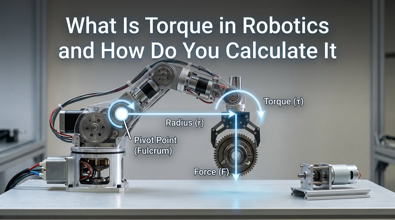
Torque is the rotational force that causes an object to turn around an axis or pivot point, and in robotics it determines how much weight a robot can lift, how precisely its joints move, and how much power its motors must generate. Without sufficient torque, even the most sophisticated robot arm collapses under its own weight.
If you have ever struggled to choose the right motor for a robotic arm, wondered why your joints stall under load, or needed to size an actuator for a humanoid leg, this guide breaks down torque in robotics from the ground up. We cover the physics, the formulas, units, and a complete step-by-step calculation you can apply to your own builds.
Our team has spent years working with robotic arms, mobile platforms, and humanoid prototypes, and we have distilled the calculation process into clear, repeatable steps. By the end, you will know exactly how to determine the torque requirements for any robotic joint.
Table of Contents
What Is Torque in Robotics
Torque in robotics is the twisting force a motor or actuator produces to rotate a joint, lift a payload, or drive a wheel. Think of it as the rotational equivalent of linear force. Where a linear force pushes something in a straight line, torque rotates it.
A helpful analogy is opening a door. When you push a door near the handle (far from the hinge), it swings easily. Push the same door right next to the hinge, and it feels nearly impossible to move. The force you apply is the same, but the distance from the pivot point changes the torque dramatically. That distance is called the moment arm.
In robotics, this concept governs everything. A shoulder joint on a robot arm needs high torque because it supports the weight of the entire arm plus whatever the gripper holds. A wrist joint needs less because it only rotates the end effector. Understanding this distribution of torque across joints is the foundation of proper robot design.
Torque also determines acceleration. A motor with more torque can spin up a heavy load faster, while a motor with insufficient torque will struggle, stall, or overheat. That is why motor sizing based on torque requirements is one of the first steps in any robotics project.
The Torque Formula Explained
The torque formula is straightforward: torque equals force multiplied by the perpendicular distance from the pivot point. In mathematical notation, this is written as tau (τ) = r x F, where τ is torque, r is the moment arm length, and F is the applied force.
Here is what each component means in practice:
τ (Torque): The rotational force, measured in Newton-meters (Nm) or pound-feet (lb-ft). This is the number you are usually solving for when designing a robot.
r (Moment Arm): The perpendicular distance from the axis of rotation to the point where force is applied. On a robot arm, this is the length from the joint to the center of mass of the load. A longer arm means higher torque requirements for the same weight.
F (Force): The linear force being applied. In most robotic applications, this comes from gravity acting on the payload and the arm itself. For a mass of m kilograms, the gravitational force is F = m x g, where g is 9.81 m/s squared.
So for robotics, the formula often expands to τ = m x g x r. This gives you the minimum torque a joint must produce to hold a load stationary against gravity. We will work through a full example later in this guide.
There is also an angular version of the formula: τ = I x α, where I is rotational inertia and α is angular acceleration. This version matters when you need to calculate how quickly a motor can spin up a load, not just whether it can hold it.
Torque Units of Measurement
Torque is measured in Newton-meters (Nm) in the SI system and pound-feet (lb-ft) in the imperial system. The Newton-meter is the standard unit used in robotics engineering worldwide, and most motor datasheets list torque ratings in Nm or milliNewton-meters (mNm) for small servos.
One Newton-meter represents the torque produced by applying one Newton of force at a distance of one meter from the pivot. To put that in perspective, holding a 1-kilogram weight at arm’s length (about 0.5 meters) produces roughly 4.9 Nm of torque at your shoulder.
Converting between units is simple. One Newton-meter equals approximately 0.7376 pound-feet. One pound-foot equals approximately 1.356 Newton-meters. If you are working with a motor rated in oz-in (ounce-inches), which is common for small hobby servos, one oz-in equals about 0.00706 Nm.
Here is a quick reference for common conversions:
1 Nm = 0.7376 lb-ft
1 lb-ft = 1.356 Nm
1 Nm = 141.6 oz-in
1 oz-in = 0.00706 Nm
1 kgf-cm = 0.098 Nm
Always check which unit your motor datasheet uses before doing calculations. Mixing Nm and lb-ft is one of the most common errors we see in robotics forums.
How to Calculate Torque for Robot Joints
Calculating torque for a robot joint requires four steps: identify the load, measure the moment arm, apply the torque formula, and add a safety factor. Let us walk through each step using a real robotic arm example that forum builders encounter constantly.
Step 1: Identify the Load
Determine the total mass the joint must support. This includes the payload, the gripper, and every link of the arm beyond that joint. For a shoulder joint, the load is everything from the shoulder outward. For a base joint, the load is the entire arm plus payload.
For our example, imagine a robot arm with a 5 kg payload at the end effector, a 2 kg forearm, and a 3 kg upper arm. The shoulder joint must support all 10 kg.
Step 2: Measure the Moment Arm
Find the perpendicular distance from the joint axis to the center of mass of the load. For a horizontally extended arm, this is simply the horizontal distance to the payload.
In our example, say the upper arm is 0.4 meters and the forearm is 0.6 meters, fully extended horizontally. The payload sits 1.0 meter from the shoulder joint. The combined center of mass of the arm links and payload falls somewhere along that length, but for a conservative estimate, we calculate torque at full reach with the payload at 1.0 meter.
Step 3: Apply the Torque Formula
Use the expanded formula: τ = m x g x r. Plug in the mass, gravitational acceleration (9.81 m/s squared), and the moment arm distance.
For the payload alone: τ = 5 x 9.81 x 1.0 = 49.05 Nm. For the arm links, assume their centers of mass are at roughly half their lengths. The upper arm center of mass is at 0.2 m and the forearm at 0.7 m from the shoulder. So arm link torque = (3 x 9.81 x 0.2) + (2 x 9.81 x 0.7) = 5.89 + 13.73 = 19.62 Nm. Total torque at the shoulder = 49.05 + 19.62 = 68.67 Nm.
Step 4: Add a Safety Factor
Multiply your calculated torque by a safety factor to account for acceleration, friction, and real-world losses. A common safety factor is 1.5 to 2.0 for most robotics applications.
Using a safety factor of 1.5: 68.67 x 1.5 = 103 Nm. This is the torque your shoulder motor and gear system should be rated for. Forum builders consistently report needing over 100 Nm for 5 kg payload arms with standard link lengths, which matches our calculation closely.
If the arm moves dynamically rather than just holding position, add the angular acceleration torque using τ = I x α on top of the static holding torque. This is how you handle fast pick-and-place operations.
Motor Torque Calculation
Motor torque calculation uses a different formula based on the motor’s torque constant. Every electric motor has a torque constant, Kt, measured in Nm per ampere. The formula is τ = Kt x I, where I is the current flowing through the motor.
For example, a brushless motor with a Kt of 0.05 Nm per amp running at 20 amps produces 1.0 Nm of torque at the motor shaft. This is the direct-drive torque before any gearing.
For brushed DC motors, the same formula applies. The Kt value is usually found on the motor datasheet. If your datasheet only lists Kv (RPM per volt), you can calculate Kt using the relationship: Kt = 1 / (Kv x 0.0115), giving Kt in Nm per amp when Kv is in RPM per volt.
This matters because the motor shaft torque is rarely enough for robotic joints. A typical brushless servo might produce 0.5 Nm directly, but a robot shoulder needs 100 Nm. The gap is bridged by gear reduction, which multiplies torque at the cost of speed.
To select a motor, divide your required joint torque by your gear ratio. If you need 100 Nm at the joint and use a 50:1 harmonic drive, the motor only needs to produce 2.0 Nm. Then check whether the motor can produce 2.0 Nm using τ = Kt x I, and verify the required current is within your driver’s limits.
Real-world torque at the motor also differs from theoretical values by 10 to 50 percent due to losses from winding resistance, friction in the gearbox, and ESC inefficiencies. Always budget for these losses in your design.
Static vs Dynamic Torque
Static torque is the force needed to hold a load stationary against gravity, while dynamic torque is the additional force required to accelerate or decelerate that load during motion. Both must be calculated for a properly designed robot.
Static torque keeps a robot arm from drooping when it holds a position. We already calculated it: τ = m x g x r. This is the baseline, and if your motor cannot produce at least this much torque, the arm will fail to hold position.
Dynamic torque comes into play when the arm moves. Accelerating a load requires extra torque proportional to the rotational inertia and angular acceleration, as described by τ = I x α. Fast movements demand significantly more torque than slow ones, even with the same payload.
The total torque requirement is static torque plus dynamic torque. A robot that lifts slowly might need only 10 percent extra torque for motion. A high-speed pick-and-place arm could need 50 to 100 percent more than its static holding torque.
Ignoring dynamic torque is one of the most common reasons robot arms work on the bench but fail during actual operation. Always calculate both, and size your motor for the worst-case combination.
Gear Ratio Effects on Torque
Gear reduction multiplies torque while dividing speed by the same factor. A 10:1 gear ratio produces ten times the output torque at one-tenth the output speed. This is why almost every robotic joint uses some form of gearing between the motor and the load.
In practice, a small motor producing 0.3 Nm can generate 30 Nm at the joint with a 100:1 gear reduction. This is how compact robot actuators achieve the torque needed for heavy payloads without massive motors.
Industrial robot arms frequently use 50:1 or larger harmonic gear reductions. Harmonic drives, also called strain wave gears, are popular because they offer high reduction ratios in a compact, backlash-free package. A 50:1 harmonic drive turns a 2 Nm motor into a 100 Nm joint actuator.
The trade-off is speed. A motor spinning at 3000 RPM through a 50:1 reduction outputs only 60 RPM at the joint. For applications needing both high torque and high speed, you need a more powerful motor, a direct-drive configuration, or a more complex transmission system.
Gear efficiency also matters. Harmonic drives typically run at 70 to 90 percent efficiency, meaning you lose 10 to 30 percent of your torque to friction. Planetary gears can reach 95 percent efficiency but with more backlash. Factor this into your torque budget.
Common Mistakes in Torque Calculation
Even experienced builders make mistakes when calculating torque for robotic applications. Here are the most frequent errors we see on robotics forums and how to avoid them.
Mistake 1: Forgetting the safety factor. Calculating the bare minimum holding torque and choosing a motor rated for exactly that value. Real motors have manufacturing tolerances, gearboxes have friction, and payloads shift. Always multiply by at least 1.5, and use 2.0 for dynamic or safety-critical applications.
Mistake 2: Ignoring dynamic loads. Only calculating static holding torque and forgetting about angular acceleration. When the arm swings quickly, it needs far more torque than when it is holding still. Calculate τ = I x α for your expected speeds and add it to the static value.
Mistake 3: Confusing joint torque with motor torque. These are not the same thing. Joint torque is what the output shaft must produce after gearing. Motor torque is what the raw motor generates before the gearbox. Always divide joint torque by gear ratio to find the required motor torque.
Mistake 4: Overlooking friction and efficiency losses. Theoretical calculations assume perfect efficiency, but real gearboxes lose 10 to 30 percent of torque to friction. A 100 Nm theoretical output from a 50:1 gearbox might only deliver 75 to 90 Nm in practice. Account for this with an efficiency factor.
Mistake 5: Not considering worst-case arm orientation. Torque is highest when the arm is fully extended horizontally. An arm that works fine when curled close to the base may stall when fully extended. Always calculate for maximum reach.
Real-World Torque Requirements
Different robot types have dramatically different torque needs. Here are concrete numbers from real-world robotic systems to give you a sense of scale.
Humanoid robots: Each leg joint in a bipedal humanoid typically requires 80 to 200 Nm of torque to support body weight and maintain balance during walking. Knee joints bear the highest loads during squatting and climbing motions. Advanced humanoids like those being developed in 2026 use high-torque actuators with 100:1 or greater gear reductions at every major joint.
Industrial robot arms: A typical 6-DOF industrial arm rated for a 30 kg payload can exceed 3000 Nm of torque at the base joint when fully extended. These arms use powerful servo motors paired with large harmonic drives. The base and shoulder joints need the most torque, while wrist joints need relatively little.
Mobile robots: Wheeled platforms need torque to overcome rolling resistance, climb inclines, and accelerate. The drive torque formula accounts for robot mass, wheel radius, desired acceleration, and incline angle. A 20 kg mobile robot with 0.05 meter wheels climbing a 15-degree incline might need about 2.5 Nm per wheel, before safety factors.
Hobby servo arms: Small desktop robot arms using standard servos typically operate in the 1 to 20 Nm range per joint. These use plastic or metal gear servos with built-in reduction, and payloads are measured in hundreds of grams rather than kilograms.
Frequently Asked Questions
What is torque and how is it calculated?
Torque is the rotational force that causes an object to turn around an axis. It is calculated by multiplying the applied force by the perpendicular distance from the pivot point (the moment arm). In robotics, the formula is typically torque equals mass times gravitational acceleration times distance: τ = m × g × r.
What is the formula for torque?
The torque formula is τ = r × F, where τ is torque, r is the perpendicular distance from the axis of rotation (moment arm), and F is the applied force. For gravitational loads in robotics, this expands to τ = m × g × r, where m is mass in kilograms, g is 9.81 m/s², and r is the moment arm in meters.
What does torque mean in robotics?
In robotics, torque refers to the twisting force a motor or actuator generates to rotate a joint, lift a payload, or drive a wheel. It determines how much weight a robot can handle, how fast it can accelerate, and how precisely it maintains position under load.
How to explain torque for dummies?
Imagine opening a door by pushing near the handle. It swings easily. Now try pushing right next to the hinge with the same force. It barely moves. That difference is torque. The further from the hinge you push, the more turning force you create. Torque is simply force multiplied by how far from the pivot you apply it.
Conclusion
Understanding what torque in robotics is and how to calculate it gives you the foundation for designing arms, legs, and drive systems that actually work. The core formula τ = m × g × r gets you the static holding torque, adding τ = I × α handles dynamic motion, and gear reduction bridges the gap between small motors and heavy loads.
The key takeaways are simple. Calculate torque at maximum reach, always include a safety factor of 1.5 to 2.0, account for gear efficiency losses, and never confuse motor torque with joint torque. If you follow the four-step process in this guide, you can size actuators for any robotic project with confidence.