
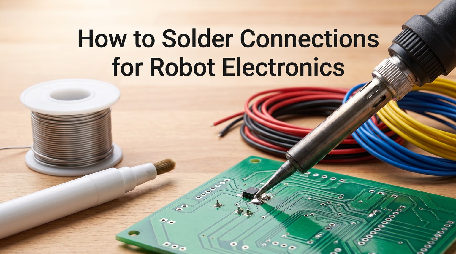
Learning how to solder connections for robot electronics is the single most important skill you can develop as a robot builder. A beautifully designed robot with perfectly tuned code will still fail on the competition floor if a single solder joint goes cold or a motor wire shakes loose after 200 rounds of combat.
I have spent years building robots for competitions, educational workshops, and industrial prototypes. In that time, I have seen every soldering failure you can imagine. Motors that cut out mid-match, sensors that flicker with every vibration, batteries that refuse to charge because of a hairline crack in a joint buried under heat shrink.
This guide walks you through everything you need to know. We will cover safety, tool selection, the core soldering technique, robot-specific wiring for motors and batteries, how to recognize good and bad joints, vibration-proofing your connections, troubleshooting, and even the crimp-versus-solder debate that splits the robotics community.
If you are just getting started with robot wiring, this pairs well with our complete robot power wiring guide, which covers the bigger picture of power distribution and wire gauge selection.
Table of Contents
Why Proper Soldering Matters for Robot Electronics
Robots live in harsh electrical environments. Every connection on your robot must survive constant vibration, sudden impacts, rapid temperature swings, and high-current pulses that would destroy a typical breadboard prototype. A solder joint that works fine on your workbench can fail within minutes on a running chassis.
The difference between a reliable robot and one that randomly resets often comes down to connection quality. Poor soldering causes voltage drops that trigger brownouts, intermittent sensor readings that ruin autonomous navigation, and motor connections that arc and heat until they melt through their insulation.
I once watched a combat robot lose a semifinal match because a motor lead had been soldered to an ESC pad without proper tinning. The joint looked perfect under casual inspection, but under load it developed enough resistance to drop the supply voltage below the controller’s brownout threshold. If you have ever asked yourself why your robot browns out and resets, the answer is frequently a soldering issue hiding in your power path.
Every connection on your robot needs both good electrical conductivity and solid mechanical strength. Solder is not glue. It provides the electrical bond, but the mechanical hold comes from how you prepare and position the wires and components before the solder even touches the joint.
Essential Safety Precautions
Soldering involves a tool heated to 350 degrees Celsius, molten metal, and chemical fumes. Before you pick up an iron, you need to understand the hazards and protect yourself properly.
Eye and Hand Protection
Always wear safety glasses when soldering. Hot flux can spit, and trimmed component leads shoot across the room with surprising velocity when you snip them with flush cutters. I have pulled wire snippets out of my shirt more times than I care to admit.
Wear closed-toe shoes and avoid loose clothing that could brush against the hot iron. The tip of a soldering iron reaches temperatures that cause instant second-degree burns on contact with skin.
Fume Safety and Ventilation
Solder fumes contain flux residues and, if you use leaded solder, microscopic lead particles. Always solder in a well-ventilated area. A fume extractor that pulls air away from your face is a worthwhile investment if you solder regularly. At minimum, work near an open window or use a small fan to direct fumes away from your breathing zone.
Never eat or drink at your soldering station. Wash your hands thoroughly after every soldering session, especially before touching your face or handling food.
Lead Safety and Lead-Free Solder
Lead-free solder is becoming the standard for good reason. Leaded solder (typically 60/40 or 63/37 tin-to-lead ratio) is easier to work with because it melts at a lower temperature and flows more smoothly, but it contains a neurotoxin that accumulates in your body over time. Lead-free solder (SAC305 is the most common alloy) requires slightly higher temperatures but eliminates the health risk entirely.
For robot electronics in educational settings or any project that children might handle, lead-free solder is mandatory. For personal workshop use, the choice is yours, but I recommend learning on lead-free from the start so you never have to unlearn bad habits developed from the easier flowing characteristics of leaded solder.
Burn and Fire Prevention
Always return your iron to its stand when not actively soldering. A hot iron resting on a desk will scorch the surface within seconds and can ignite paper or melt through wire insulation. Keep a fire extinguisher rated for electrical fires within reach of your workbench.
Never try to catch a dropped soldering iron. Let it fall. A cracked tip is cheaper than a serious burn on your hand.
Tools and Materials Needed
Good soldering starts with the right tools. You do not need the most expensive equipment, but you do need equipment that performs consistently. Here is what every robot electronics workbench should have.
Soldering Iron
A temperature-controlled soldering iron is non-negotiable for robot electronics. The cheap unregulated irons that come in bargain kits hover around an uncontrolled temperature that is either too hot or too cold depending on airflow. A temperature-controlled station lets you dial in the exact heat needed for your solder type and component.
Look for an iron that reaches 350 to 400 degrees Celsius, accepts interchangeable tips, and heats up in under 30 seconds. A chisel tip in the 2 to 3 millimeter range is the most versatile choice for robot wiring and through-hole PCB work. Fine conical tips are useful for surface-mount work but transfer heat too slowly for large motor wire connections.
Solder Wire
Use rosin-core solder with a diameter of 0.6 to 0.8 millimeters for electronics work. The flux core inside the solder wire cleans oxidation from the joint as you heat it, which is what allows the solder to wet and flow properly. Thicker solder (1.0 millimeter and above) is better for large motor terminals and battery connectors where you need to deposit a lot of material quickly.
For lead-free solder, SAC305 (96.5 percent tin, 3 percent silver, 0.5 percent copper) is the industry standard. It melts around 217 degrees Celsius and produces strong, reliable joints when used at the correct temperature.
Flux
Additional flux in a pen or paste form is essential for difficult joints. The flux inside rosin-core solder is usually enough for clean, fresh components, but old or oxidized wires, recycled pads, and large connections all benefit from extra flux applied before heating.
Many beginners ask whether they can use vaseline or other household substances as flux. The short answer is no. Genuine electronic flux contains active chemicals designed to dissolve oxide layers at soldering temperatures. Vaseline and petroleum-based products do not have these properties and will carbonize on your iron, contaminating your joint and ruining your tip.
Helping Hands and Workholding
Soldering requires both of your hands, one for the iron and one for the solder wire. Helping hands (sometimes called third hands) with adjustable alligator clips hold your wires and PCB in position while you work. A magnetic workholding surface or a small vise is useful for larger assemblies.
For robot wiring harnesses, I use a board with evenly spaced nails to route and hold wires in position while I solder and apply heat shrink. This keeps everything aligned and prevents the wires from shifting during the critical cooling period.
Cutting and Cleaning Tools
Flush cutters trim component leads flush with the PCB surface without leaving sharp stubs. Wire strippers sized for the gauges you work with (typically 20 to 14 AWG for robot electronics) are essential. A pair of needle-nose pliers helps bend and position component leads.
For tip maintenance, keep both a brass wool tip cleaner and a damp cellulose sponge on your bench. Brass wool is gentler on tips and does not cause thermal shock the way a wet sponge does. A tub of tip tinner (a paste that restores oxidized tips) will save you from throwing away blackened, unusable tips.
Heat Shrink and Electrical Tape
Heat shrink tubing is the standard insulation method for soldered wire connections on robots. Slide a piece over your wire before soldering, then shrink it down with a heat gun after the joint cools. Heat shrink provides both electrical insulation and mechanical strain relief. Avoid electrical tape for permanent connections, as the adhesive degrades and the tape unravels over time, especially in warm robot chassis.
Desoldering Tools
Keep a solder wick (braided copper wire that absorbs molten solder) and a desoldering pump (spring-loaded suction tool) on hand. These are essential for fixing mistakes, removing components, and cleaning up solder bridges. For surface-mount rework, a hot air rework station is a worthwhile upgrade.
Magnification and Inspection
A magnifying lamp or a digital USB microscope helps you inspect joints that look fine to the naked eye but have hidden defects. I do my final inspection under 10x magnification on every robot I build, and it has caught problems I would have missed entirely.
How to Solder Connections for Robot Electronics: Step-by-Step Technique
Here is the core technique for soldering connections for robot electronics. Follow these steps every time, and your joints will be reliable from the first attempt.
Step 1: Prepare Your Iron and Tip
Turn on your iron and let it reach operating temperature, typically 350 degrees Celsius for lead-free solder or 320 degrees Celsius for leaded. Clean the tip on brass wool, then apply a small amount of fresh solder to coat it. This process is called tinning, and it ensures good thermal contact between the iron and your joint.
A properly tinned tip should look shiny and silver. If the tip appears dull, black, or pitted, clean it on brass wool and re-tin. If tinning does not restore the shine, apply tip tinner paste according to the manufacturer instructions.
Step 2: Prepare the Joint
Strip wire insulation to expose about 3 to 5 millimeters of bare copper. Twist the strands of stranded wire lightly so they stay together. For through-hole components, insert the leads through the PCB pads and bend them slightly to hold the component in place.
If the surfaces look dull or oxidized, apply a small amount of flux. Fresh components and new PCBs usually need no additional flux beyond what is in your rosin-core solder.
Step 3: Tin Both Surfaces
For wire-to-wire or wire-to-terminal connections, tin each surface separately before joining them. Apply the iron to the wire, feed a small amount of solder into the wire (not onto the iron tip), and let it wick through the strands. The tinned wire should have a uniform silver coating with no visible copper.
For through-hole PCB soldering, you generally do not pre-tin the pad and lead. Instead, you solder them together in one operation.
Step 4: Heat the Joint, Not the Solder
This is the single most important rule in soldering and the most common mistake beginners make. Place the iron tip against both surfaces you want to join simultaneously, so that heat transfers into the wire and the pad (or terminal). Wait about one second for the surfaces to reach soldering temperature.
Then feed solder wire into the joint from the opposite side of the iron. The solder should melt on contact with the heated surfaces and flow toward the heat source. If the solder melts on the iron tip instead of flowing into the joint, you are applying solder to the iron rather than to the joint, and you will get a weak, unreliable connection.
Step 5: Apply the Right Amount of Solder
Feed solder until the joint is filled but not overflowing. For a through-hole pad, the solder should form a concave fillet that covers the pad and rises slightly up the component lead. For a wire connection, the solder should fill the gaps between the strands and coat the entire exposed area.
The 3-second rule in soldering refers to the total heating time. Your iron should be in contact with the joint for no more than 2 to 3 seconds. Any longer and you risk damaging heat-sensitive components, lifting PCB pads, or melting wire insulation. If you need more time, you are either using the wrong tip, the wrong temperature, or insufficient flux.
Step 6: Remove Solder First, Then the Iron
Stop feeding solder and remove the solder wire. Then, about half a second later, remove the iron. This sequence ensures the last bit of molten solder is pulled into the joint by surface tension rather than clinging to your iron tip as you pull away.
Step 7: Hold Everything Still While It Cools
Do not move the joint for 3 to 5 seconds after removing the iron. The solder transitions from liquid to solid almost instantly, but the crystal structure that gives the joint its strength forms during this brief cooling window. If anything shifts during cooling, you get a dull, grainy, weak joint known as a disturbed joint.
Step 8: Inspect and Clean
Examine the joint under magnification. A good joint is shiny (for leaded solder) or smooth and satin-finished (for lead-free solder), with a concave fillet that smoothly transitions from the pad to the component lead. Clean any flux residue with isopropyl alcohol and a small brush, as leftover flux can cause corrosion over time.
For wire connections, slide heat shrink over the joint and shrink it with a heat gun. For PCB joints, clip any excess component leads flush with your flush cutters.
Soldering Wires for Robot Motor and Battery Connections
Wire soldering is where most robot builders run into trouble. Motor leads, battery connections, and ESC wiring all involve stranded wire carrying significant current, and these joints must handle vibration and heat without failing.
Tinning Stranded Wire
Stranded wire must be tinned before you make any connection. Strip 4 to 5 millimeters of insulation, twist the strands lightly clockwise to bundle them, apply flux if the wire looks dull, then heat the wire with your iron and feed solder into the strands. The solder should wick through the entire bundle by capillary action, creating a solid silver-colored conductor that still fits through your connector or pad hole.
Avoid over-tinning. If you apply so much solder that the wire becomes a rigid blob, it will not fit through pads and the stiff section will act as a stress concentration point that eventually breaks under vibration.
Soldering Wire to Wire (Splices)
For robot wiring harnesses, you often need to splice two wires together. The strongest mechanical splice is the Western Union or lap joint. Tin both wires, overlap them by about 5 millimeters, twist them together lightly, then apply heat and a small amount of solder to fuse the tinned surfaces.
Always cover splices with heat shrink tubing that extends at least 5 millimeters past the splice on each side. For robot applications, I use adhesive-lined heat shrink, which melts an inner layer of glue that seals the joint against moisture and adds significant mechanical strength.
High-Current Motor Connections
Motor terminals on combat robots and large drive systems draw bursts of 30 to 100 amps or more. These connections require special attention because the large gauge wire (often 12 to 14 AWG) and thick motor tabs act as massive heat sinks that suck heat away from your joint faster than a small iron can supply it.
Use a high-wattage iron (60 watts or more) or a large chisel tip on your temperature-controlled station. Pre-tin the motor tab and the wire separately, then join them with additional solder and a longer dwell time. Clamp the motor in a vise so it does not move during the process, and use a clip-on heat sink or aluminum alligator clip on the motor lead between the tab and the motor body to prevent heat from traveling inward and damaging internal windings.
Battery Connection Safety
Soldering directly to battery terminals is dangerous and should be avoided whenever possible. The heat from soldering can melt internal seals, damage cell chemistry, or in extreme cases trigger thermal runaway in lithium-based cells. Always use pre-fabricated battery packs with welded tabs, and solder only to the tab, never to the cell itself.
If you must solder battery leads, work fast, use the highest heat setting your iron supports so you minimize contact time, and hold the battery cell body to monitor temperature. If the cell feels warm to the touch, stop immediately. Our battery selection guide for robotics covers pack options that minimize or eliminate the need for direct cell soldering.
Connector Soldering
Common robot connectors like XT60, XT90, and Deans require soldering large pins. Tin both the pin cup and the wire, place the wire into the cup, then apply heat from the outside of the pin while feeding a small amount of solder into the joint. Hold the wire steady until the solder solidifies. Always use the connector’s half-shell housing to hold the pins during soldering, as bare pins can short against each other on your workbench.
Be careful not to overfill connector cups. Excess solder on the outside of the pin prevents the pin from seating properly in its housing and creates a shorting risk with adjacent pins.
Recognizing Good vs Bad Solder Joints
Training your eye to recognize joint quality is just as important as learning the soldering technique itself. Here is what to look for when inspecting your robot connections.
Characteristics of a Good Solder Joint
A good solder joint has a smooth, concave fillet that transitions gradually from the PCB pad up to the component lead. The surface should be shiny for leaded solder or have a fine satin finish for lead-free solder. There should be no gaps, no icicles, and no solder balls nearby.
The solder should wet both surfaces evenly. On a through-hole joint, you should see solder flow completely through the plated hole and form a slight fillet on the opposite side of the board. The edges of the fillet should blend smoothly into the surfaces with no distinct boundary line.
Signs of a Cold Solder Joint
A cold solder joint is the most dangerous failure mode in robot electronics because it looks deceptively similar to a good joint but conducts electricity poorly or intermittently. Cold joints appear dull, grainy, or frosted rather than shiny. The fillet may be rounded or blobby instead of concave, and the solder may not fully wet both surfaces.
Cold joints happen when the joint surfaces were not hot enough when the solder was applied, or when the joint was moved during cooling. To fix a cold joint, reheat it with your iron, add a small amount of fresh flux-core solder, and hold everything still until it cools.
Solder Bridges
A solder bridge is an unintended connection between two adjacent pads or pins. These are especially common on dense PCBs and connector headers where pin spacing is tight. Bridges appear as thin filaments or blobs of solder spanning the gap between pins.
To remove a solder bridge, apply flux to the area, press solder wick flat against the bridge, and hold your hot iron on top of the wick. The braid will absorb the excess solder through capillary action. Lift the wick and iron simultaneously to avoid soldering the wick to your board.
Other Common Visual Defects
Icicles are pointed spikes of solder that form when you pull the iron away too slowly or use too much solder. Solder balls are tiny spheres that roll off the joint and can short nearby pads. Insufficient solder leaves a joint where you can still see the wire or lead through a thin, incomplete coating.
A bad soldering job looks like this: dull gray joints, solder blobs that do not wet the pad, visible gaps between the solder and the component lead, bridges between adjacent pins, and wire insulation that is melted or scorched from excessive heat. Any of these signs means the joint needs to be redone.
Vibration-Resistant Soldering and Strain Relief for Robots
Robots vibrate, shake, crash, and bounce. A solder joint that is perfectly adequate on a static circuit board will crack and fail on a moving chassis if you do not design for vibration from the start. This is the area where most generic soldering guides fall short, and it is the area where robot-specific technique matters most.
The Rule of Mechanical Support First
Solder should never be the sole mechanical connection in a robot. Every wire should be physically secured by some other means, with solder providing only the electrical bond. Zip ties, adhesive anchors, cable clamps, and PCB-mounted strain relief features all prevent wires from flexing at the solder joint.
The point where a wire enters a solder joint is the most vulnerable location, because the rigid solder creates a transition point between the flexible wire and the stiff joint. Any bending force concentrates at this transition, and repeated flexing will eventually fatigue the copper strands and crack the joint.
Heat Shrink as Strain Relief
Adhesive-lined heat shrink tubing is your best friend for robot wiring. When shrunk over a soldered connection, it provides a flexible boot that gradually transitions stiffness from the wire to the joint. The adhesive layer bonds to the insulation and adds significant pull-out strength. Always position heat shrink so it overlaps the wire insulation by at least 5 millimeters on each side of the joint.
For extra-critical connections, use dual-wall heat shrink or add a second layer of standard heat shrink over the first. Combat robot builders often add a zip tie over the heat shrink at the wire entry point for redundant strain relief.
Routing and Anchoring
Route wires along chassis members and anchor them every 50 to 100 millimeters with zip ties or adhesive mounts. Avoid routing wires across moving joints or through areas where they can be pinched. Leave service loops (small amounts of slack) at connector endpoints so vibration does not transmit pulling forces directly to the solder joint.
On PCBs, through-hole mounted components are more vibration-resistant than surface-mount equivalents because the leads pass through the board and are soldered on both sides. For heavy components like large capacitors or connectors, apply a dab of silicone adhesive or hot glue to the base as additional mechanical support.
Connector Selection for Vibration Environments
Choose connectors with positive locking mechanisms for robot applications. XT60 and XT90 connectors have friction-fit housings that resist vibration, while Deans connectors rely on spring tension alone and can work loose over time. For sensor and signal connections, JST-SM connectors with locking tabs are far more reliable than friction-only headers.
For any connector that carries critical power or signal paths, add a secondary mechanical retention method. A zip tie looped around the connector pair or a small strip of Velcro will prevent accidental disconnection during impacts.
Common Mistakes to Avoid
Every experienced solderer has made these mistakes. Recognizing them early will save you hours of debugging mysterious robot failures.
Applying Solder to the Iron Instead of the Joint
This is the beginner’s most common error when soldering. Melting solder on the iron tip and then trying to smear it onto the joint produces a weak mechanical bond with poor electrical contact. The joint may look acceptable but will fail under current load or vibration. Always heat the joint surfaces first, then feed solder into the joint so it flows from the cold side toward the heat.
Using Too Low a Temperature
Fear of damaging components leads many beginners to set their iron too low. A cold iron means longer dwell time, which actually transfers more total heat into your components than a hot iron used quickly. For lead-free solder, 350 to 380 degrees Celsius gives you enough thermal headroom to complete a joint in 2 to 3 seconds.
Moving the Joint Before It Cools
Even a tiny shift during the 2-second cooling window produces a disturbed joint with a grainy, weak crystalline structure. Brace your hands on the workbench, use helping hands to hold components, and count to three before letting go.
Skipping Flux on Difficult Joints
Flux is not optional for oxidized wires, recycled pads, or large connections. Without flux, solder will ball up on the surface instead of wetting it. If your solder is refusing to flow, the fix is almost always more flux and more heat.
Neglecting Tip Maintenance
A black, oxidized tip cannot transfer heat efficiently, which leads to long dwell times and poor joints. Clean your tip on brass wool before every joint, re-tin it after every few joints, and use tip tinner when the shine will not come back. When you finish a soldering session, leave a fresh coat of solder on the tip before turning the iron off. This protects the tip plating from oxidation during storage.
Using Too Much Solder
More solder does not make a stronger joint. A joint that looks like a dome or a sphere has too much solder, which can hide defects underneath and create shorts on dense boards. The ideal joint has just enough solder to form a smooth concave fillet.
Troubleshooting Soldering Problems
When things go wrong, here is how to diagnose and fix the most common soldering problems in robot electronics.
Solder Will Not Flow Into the Joint
If your solder balls up on the surface instead of wetting the joint, the cause is almost always insufficient heat, lack of flux, or surface oxidation. Increase your iron temperature by 10 to 20 degrees, apply fresh flux, and clean the surfaces with isopropyl alcohol. For heavily oxidized wires, physically scrape the surface with a knife or abrasive pad before applying flux.
Soldering Iron Tip Turns Black
Tip blackening is caused by oxidation at high temperatures. This happens when you leave the iron on for long periods without tinning, or when you use aggressive cleaning methods that strip the protective plating. Restore the tip by rubbing it in tip tinner paste on a hot setting, then wipe on brass wool. If the tip remains black after two applications, it needs replacement.
Prevent blackening by lowering your iron temperature during idle periods (many stations have a sleep function), always leaving a solder coat on the tip when powered off, and never using sandpaper or files to clean tips.
Lifted or Damaged PCB Pads
Pads lift when they are heated too long or when force is applied to a component while the solder is still molten. This is especially common during desoldering. Once a pad lifts, it cannot be re-bonded to the board substrate. Bridge the broken trace to the nearest intact copper using a small wire jumper, and secure the jumper with UV-curable solder mask or epoxy.
Intermittent Connections in Finished Robots
If your robot works on the bench but fails during operation, suspect cold joints, cracked joints from vibration, or wires that have fatigued at strain points. Inspect every soldered connection under magnification, looking for hairline cracks around the fillet. Gently wiggle each wire while the robot is powered (with the drive wheels off the ground) and watch for intermittent behavior.
For robots that use separate power supplies for logic and motors, poor soldering on the common ground return can cause signal noise and brownouts. Our article on why robots use separate power for logic and motors explains how power architecture affects connection requirements.
Components Overheating During Soldering
Sensitive components like LEDs, ICs, and some sensors can be damaged by prolonged heat exposure. Use a clip-on heat sink between the solder joint and the component body to draw heat away. Minimize dwell time by using the correct tip size and temperature. For through-hole ICs, use a socket so you only solder the socket pads, not the IC itself.
Desoldering Techniques for Robot PCBs
Mistakes happen, components fail, and upgrades require removing old parts. Desoldering is a skill every bit as important as soldering.
Solder Wick (Desoldering Braid)
Solder wick is braided copper wire that absorbs molten solder through capillary action. Place the wick flat against the solder you want to remove, press your iron on top of it, and wait for the solder to flow into the braid. Apply fresh flux to the wick before use for faster absorption. Lift the iron and wick together to avoid bonding the wick to your board.
Wick is ideal for removing solder bridges, cleaning through-hole pads, and tidying up surface-mount pads. It is less effective for removing large volumes of solder from big joints.
Desoldering Pump (Solder Sucker)
A desoldering pump uses a spring-loaded plunger to create suction that pulls molten solder out of a joint. Heat the joint until the solder is fully liquid, position the pump nozzle against the joint, and trigger the plunger. The suction removes the bulk of the solder in one shot.
Pumps work well for through-hole components where you need to clear a plated hole. They are less effective on surface-mount pads. Always clean the pump nozzle after use, as accumulated solder will eventually jam the mechanism.
Hot Air Rework
A hot air rework station blows temperature-controlled air that melts all solder on a component simultaneously. This is the most effective method for removing surface-mount ICs and multi-pin components. Apply flux to the component, set the air temperature to around 350 degrees Celsius, and move the nozzle in a circular pattern until the solder melts on all pins. Lift the component with tweezers.
Hot air can damage adjacent components if not carefully directed. Use aluminum foil or Kapton tape to shield nearby parts from the heat stream.
When to Crimp vs When to Solder in Robotics
The crimp-versus-solder debate is one of the most persistent arguments in the robotics community. Both methods have their place, and understanding when to use each is key to building reliable robots.
When Soldering Is the Right Choice
Soldering is ideal for PCB connections, through-hole component mounting, splicing individual wires, and attaching wires to connector pins where no crimp tool is available. Solder creates a gas-tight, low-resistance bond that will not corrode or loosen over time when done correctly.
For sensor connections, signal lines, and any joint where space is tight, soldering is usually the most practical option.
When Crimping Is the Right Choice
Crimping is superior for high-vibration environments where wire flexibility is critical. A proper crimp connection uses a terminal that is mechanically compressed around the wire strands, creating a cold weld that is as conductive as solder but retains more flexibility. Crimped connections are also faster to make in production and easier to inspect visually.
For battery terminal connections, motor power leads on large robots, and any wire that will flex during operation, crimped terminals with heat shrink boots outperform soldered joints. The flexible crimp transition reduces fatigue cracking at the wire entry point.
Never Do Both
A common mistake is crimping a terminal and then soldering it for extra security. This is counterproductive. The solder wicks into the stranded wire beyond the crimp, creating a rigid section that concentrates all flexing stress at a single point and accelerates fatigue failure. Use either crimp or solder, never both on the same connection.
For a complete picture of how your soldered connections fit into the overall robot power architecture, our guide on how to wire a robot power system safely covers wire gauge selection, fuse placement, and power distribution design.
FAQs
What is the beginner’s most common error when soldering?
The most common beginner mistake is applying solder directly to the iron tip instead of heating the joint surfaces first and then feeding solder into the joint. This produces a weak bond with poor electrical contact that looks acceptable but fails under load or vibration.
What is the 3 second rule in soldering?
The 3-second rule means your soldering iron should contact the joint for no more than 2 to 3 seconds total. This prevents heat damage to components, avoids lifting PCB pads, and produces cleaner joints. If you need more time, your iron is too cold, your tip is too small, or you need more flux.
What does a bad soldering job look like?
A bad soldering job shows dull gray or grainy joints, solder blobs that do not wet the pad, visible gaps between solder and component leads, solder bridges between adjacent pins, scorched or melted wire insulation, and pointed icicles of excess solder. Cold joints may look shiny but have a rounded, ball-like shape instead of a smooth concave fillet.
Can I use vaseline as flux for soldering?
No, vaseline cannot be used as flux for soldering. Genuine electronic flux contains active chemicals that dissolve oxide layers at soldering temperatures, allowing solder to wet and flow. Vaseline is a petroleum product that will carbonize on your iron, contaminate your joint, and ruin your tip. Always use rosin flux designed for electronics.
Why isn’t my solder flowing into the joint?
Solder that balls up instead of flowing is caused by insufficient heat, lack of flux, or surface oxidation. Increase your iron temperature by 10 to 20 degrees Celsius, apply fresh flux to the joint, and clean oxidized surfaces with isopropyl alcohol or a mild abrasive before attempting the joint again.
Why is soldering becoming illegal?
Soldering itself is not becoming illegal, but leaded solder has been restricted under the RoHS (Restriction of Hazardous Substances) directive since 2006 in many regions. Lead-free solder (SAC305) is now the standard for commercial electronics manufacturing. Leaded solder is still legal for personal use, military, aerospace, and some medical applications, but lead-free is recommended for educational and hobby robotics.
Conclusion
Learning how to solder connections for robot electronics is a skill that pays dividends on every project you build. The techniques in this guide, from proper iron tinning through vibration-resistant strain relief, are the same methods that professional robot builders use to create connections that survive competition, field deployment, and years of daily use.
Start with the fundamentals. Get a temperature-controlled iron, practice the core technique on scrap wire and practice boards until your joints are consistently shiny and well-formed, then move on to your actual robot projects. The muscle memory you develop in those first practice sessions will carry through every connection you make afterward.
Remember the three principles that matter most for robot soldering. Heat the joint, not the solder. Hold everything still while it cools. And always provide mechanical strain relief so your solder joints never carry the weight of a dangling wire on a vibrating chassis.
Every cold joint you catch during inspection, every bridge you remove before powering up, and every heat-shrink boot you add for strain relief is one less failure mode between your robot and a clean, reliable run. Pick up your iron, tin your tip, and start practicing. Your next robot will be more reliable because of it.