
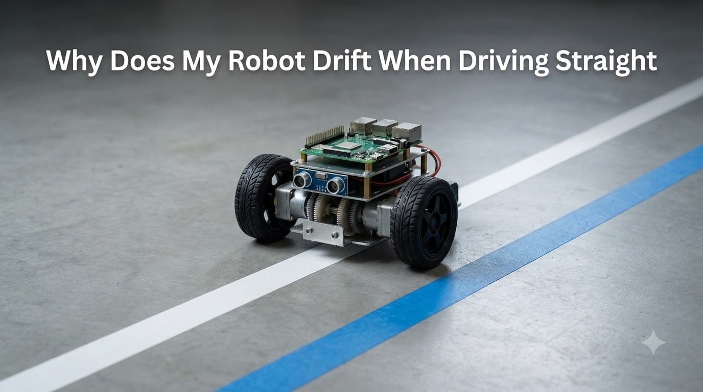
You program your robot to drive straight, and it curves to the left. You adjust the code, and now it veers right. If you have spent hours trying to figure out why does my robot drift when driving straight, you are not alone. This is one of the most common problems in robotics, affecting everyone from VEX competitors to industrial engineers.
I have seen teams on their third robot build still fighting the same persistent drift issue. One FTC team reported their robot drifted so badly that auto-aligners stopped working entirely. Another builder noticed their robot only curved when using encoders but drove fine in open-loop mode.
The good news is that drift is not a mystery. It has specific, identifiable causes, and most of them are fixable. Understanding robot chassis alignment issues is part of the equation, but there is much more to the story.
In this guide, I will walk you through every major cause of robot drift, from motor speed mismatches to environmental factors. You will learn practical hardware fixes, software solutions from basic proportional control to advanced sensor fusion, and a step-by-step troubleshooting process you can follow before your next competition or deadline.
Table of Contents
Why Does My Robot Drift When Driving Straight: The Root Causes
Robots drift when driving straight due to five main factors: motor speed differences, wheel friction variations, weight distribution imbalances, surface conditions, and mechanical asymmetries. Even a 1-2% speed difference between left and right motors causes the robot to gradually curve toward the slower side. Over distance, this small mismatch compounds into significant deviation from the intended path.
Here is a quick breakdown of the primary causes:
Motor speed mismatch – Manufacturing tolerances mean no two motors run at exactly the same speed. A 1-2% difference is enough to cause visible drift within a few feet.
Wheel friction differential – One side of the drivetrain may have more friction than the other from chain tension, bearing resistance, or axle alignment.
Weight distribution imbalance – An off-center center of gravity creates asymmetric load on the motors, changing their effective speed.
Surface conditions – Uneven floors, tiny slopes, or slippery patches cause inconsistent traction between wheels.
Mechanical asymmetries – Frame bending, gear backlash, or wheel diameter differences introduce systematic error into the drivetrain.
Most robots suffer from a combination of these factors rather than just one. The key to fixing drift is isolating which causes are contributing and addressing them in priority order.
Motor Speed Mismatch: The Most Common Culprit
Motor speed mismatch is the single biggest reason robots drift when driving straight. Even identical motors from the same manufacturer run at slightly different speeds when given the same voltage. This is because of variations in internal resistance, brush contact, magnetic field strength, and bearing friction.
Here is how it works in practice. If your left motor spins at 200 RPM and your right motor spins at 196 RPM, that is only a 2% difference. But on a differential drive robot, this means one wheel covers less ground per second than the other. The robot effectively turns slightly to the slower side every moment it drives. Over 10 feet, that tiny difference adds up to several inches of sideways drift.
I have seen builders confirm this using encoder testing. By spinning each wheel for a set time and reading the encoder counts, you can see exactly how much speed difference exists between your motors. A difference of more than 1% between encoder counts at the same power level tells you motor mismatch is a significant contributor to your drift.
Battery voltage plays a bigger role than most people realize. As the battery drains during operation, voltage drops affect each motor differently. One motor may slow down faster than the other as voltage decreases. This is why your robot might drive straight at the start of a match and drift more toward the end. No competitor in the SERP space covers this factor, but it is a real issue I have encountered repeatedly.
The fix for motor speed mismatch is almost always software-based. Instead of sending identical power values to both motors, you use feedback from encoders or an inertial sensor to continuously adjust the power sent to each motor. This is where proportional control and PID controllers come in, which I cover later in this guide.
Wheel and Drivetrain Issues
Even with perfectly matched motors, wheel and drivetrain problems can cause significant drift. The most common issues fall into four categories: wheel diameter mismatch, friction differential, chain tension problems, and frame alignment.
Wheel Diameter Mismatch
If your left and right wheels are even slightly different sizes, the robot will drift. A wheel that is 1mm larger in diameter travels farther per revolution, making that side of the robot move faster. This is a systematic error that compounds consistently over distance.
This problem is surprisingly common with foam and rubber tires that wear unevenly. I have seen teams replace one damaged wheel with a new one, creating a diameter mismatch that causes immediate drift. Always replace drive wheels in pairs.
Friction Differential
One forum user traced their drift problem to chain tension differences between the left and right sides. A tighter chain on one side creates more drag, effectively slowing that wheel even if the motor is running at the correct speed. Bearing friction, axle misalignment, and debris buildup all contribute similarly.
To diagnose friction issues, lift the robot off the ground and spin each wheel by hand. They should rotate freely and coast for roughly the same duration. If one side stops noticeably faster, you have a friction differential to address.
Gear Backlash and Power Transfer
Gear backlash effects on drive accuracy are often overlooked. When gear teeth have excessive play, power transfer becomes inconsistent. The driven wheel may momentarily speed up or slow down as backlash is taken up and released, creating unpredictable micro-drifts that are hard to correct with software alone.
Frame Bending and Alignment
A chassis that has taken impact or stress can bend slightly, shifting wheel alignment. Even a degree or two of toe-in or toe-out on a wheel changes how the robot tracks. One forum contributor reported that frame bending from stress shifted their wheel alignment enough to cause persistent drift that no software fix could fully correct.
Check wheel alignment with a straightedge along the side of each wheel. If the wheels are not parallel, you need to straighten or rebuild the affected section of the frame.
Omni and Mecanum Wheel Specific Issues
Omniwheels and mecanum wheels introduce their own drift problems. Because they can slide laterally, even tiny slopes or surface irregularities cause sideways drift that does not happen with standard wheels. One user reported their omniwheel robot drifted sideways on a barely visible slope in their testing area.
Mecanum wheels are especially sensitive to roller condition. If the rollers on one wheel spin more freely than those on another, the robot will drift. Clean and lubricate rollers regularly, and replace any that show uneven wear.
Weight Distribution and Center of Gravity
Weight distribution directly affects how much load each motor carries, which in turn affects motor speed. When the center of gravity is offset toward one side of the robot, that side’s motors work harder to maintain the same speed. Under load, a motor runs slower, creating a speed mismatch even if both motors are identical.
I encountered this with a robot that had all its electronics and battery mounted on the left side. The left motors were under significantly more load than the right, causing the robot to drift left. Moving the battery to the center reduced the drift substantially.
Here is how to check your weight distribution:
Place the robot on four identical scales, one under each wheel.
Read the weight at each corner.
The readings should be roughly equal left-to-right.
If one side carries significantly more weight, redistribute components.
A forum user noted that weight distribution fixes helped their drift but did not solve it completely. This is typical. Weight distribution addresses one contributing factor, but you usually need a combination of hardware adjustments and software correction for a complete fix.
For counterweighting, adding small amounts of weight to the lighter side is often easier than re-mounting major components. Aim for a center of gravity that sits at the geometric center of your wheelbase, both front-to-back and side-to-side.
Environmental Factors That Cause Drift
The surface your robot drives on matters more than you might think. No competitor in the current search results covers environmental factors in depth, which is a gap I want to fill here.
Surface irregularities are the most common environmental cause of drift. A slightly uneven floor, a crack, or a transition between tile and carpet can cause one wheel to lose traction momentarily. The robot drifts toward the side that lost grip. Testing on different surfaces and documenting where drift occurs can reveal environmental causes.
Temperature and humidity affect tire grip in surprising ways. Rubber and foam tires change their coefficient of friction as temperature shifts. A robot tuned to drive straight at 70 degrees Fahrenheit might drift in a 55-degree competition venue. High humidity can make smooth surfaces slicker, reducing traction consistency.
Tiny slopes cause problems especially for omniwheel and mecanum drive robots. A floor that looks flat to the human eye can have a slope of 1-2 degrees. Standard wheels resist lateral sliding, but omniwheels roll sideways freely. Even a barely perceptible slope will push the robot sideways over distance.
For surface preparation, consider these tips:
Test on the same surface type you will compete or operate on.
Check for slopes with a bubble level placed on the floor.
Clean tires before each run to remove dust and debris.
Avoid transitions between different floor materials during straight-line testing.
Documenting environmental conditions when testing helps you separate environmental drift from mechanical or software issues. If drift direction changes when you rotate the robot 180 degrees on the same surface, you are dealing with an environmental slope rather than a robot problem.
Software Solutions: How to Make Your Robot Drive Straight
Hardware fixes alone rarely produce a perfectly straight-driving robot. Even after addressing motor mismatch, friction, and weight distribution, small residual drift remains. This is where software correction becomes essential.
There are three main levels of software solutions, each more sophisticated than the last. Proportional control is the simplest and works for many applications. PID controllers add precision and handle changing conditions. Sensor fusion combines multiple feedback sources for industrial-grade accuracy.
Think of these as a progression. Start with proportional control, and only add complexity if you need better performance.
Proportional Control for Beginners
Proportional control is the simplest feedback method for making a robot drive straight. It works by measuring how far the robot has deviated from a straight heading and applying a correction proportional to that error.
The concept is straightforward. You read a heading sensor (typically a gyro or inertial sensor) and compare the current heading to the target heading (usually zero degrees for straight). The difference is your error. You multiply the error by a tuning constant called kp, and the result is added to one motor’s speed and subtracted from the other.
Here is a simple Python implementation:
target_heading = 0
kp = 0.5
base_speed = 100
while driving:
    current_heading = read_gyro()
    error = target_heading - current_heading
    correction = error * kp
    left_speed = base_speed + correction
    right_speed = base_speed - correction
    set_motor_speed(left, left_speed)
    set_motor_speed(right, right_speed)
Tuning kp is the key to making proportional control work. Start with a small value like 0.1 and increase it gradually. If kp is too low, the robot drifts and corrects too slowly. If kp is too high, the robot oscillates side to side rapidly. The sweet spot is where the robot corrects quickly without overshooting.
A good rule of thumb: if your robot drifts right by 10 degrees before correcting, your kp is too low. If it wiggles back and forth, kp is too high. Aim for a kp that brings the robot back to straight within 1-2 degrees of error.
Proportional control is sufficient for many educational and competition robots. It is simple to implement, easy to tune, and handles most drift scenarios adequately. However, it has a limitation: it only reacts to current error. It does not account for accumulated error or the rate of change. That is where PID comes in.
PID Controller: The Professional Approach
A PID controller adds two more terms to the correction calculation: integral and derivative. The proportional term (P) reacts to current error, the integral term (I) accounts for accumulated past error, and the derivative term (D) predicts future error based on the rate of change. Together, they provide much tighter control than proportional alone.
Here is what each component does:
Proportional (P) – Reacts to how far off target the robot currently is. This is the main correction force.
Integral (I) – Sums up error over time. If the robot consistently drifts 2 degrees right despite P correction, the integral term builds up and applies additional correction to eliminate that persistent offset.
Derivative (D) – Measures how fast the error is changing. It dampens the correction to prevent overshoot, making the robot settle on target smoothly.
Here is a basic PID implementation in Python:
target = 0
kp = 1.2
ki = 0.01
kd = 0.3
integral = 0
last_error = 0
while driving:
    error = target - read_gyro()
    integral = integral + error
    derivative = error - last_error
    correction = (kp * error) + (ki * integral) + (kd * derivative)
    left_speed = base_speed + correction
    right_speed = base_speed - correction
    set_motor_speed(left, left_speed)
    set_motor_speed(right, right_speed)
    last_error = error
Integral windup protection is critical. If the robot cannot correct its heading immediately (because it is against a wall, for example), the integral term keeps accumulating error. When the robot is free to move again, the massive integral value causes a violent swing. To prevent this, cap the integral term or reset it when error exceeds a threshold.
A forum user reported that their PID worked perfectly going forward but failed when driving backward with negative velocity. This is a common issue caused by sign errors in the error calculation when reversing direction. Always test your PID in both directions and adjust sign handling accordingly.
Tuning order matters. Set ki and kd to zero first, then tune kp as you would for proportional control. Once kp gives reasonable response, add a small kd value to reduce overshoot. Finally, add a small ki value to eliminate steady-state error. Increase each gradually and test between changes.
Control loop frequency also affects PID performance. Running your loop at 50-100 Hz (every 10-20 milliseconds) is typical. Too slow and the robot reacts sluggishly. Too fast and sensor noise gets amplified, especially in the derivative term.
Sensor-Based Drift Correction
Software correction is only as good as the sensor data feeding it. Choosing the right sensor for drift correction depends on your accuracy requirements, budget, and drive system. Here are the three most common options.
Quadrature Encoders and Wheel Odometry
Quadrature encoders attach to your motors or wheels and count rotations. By comparing encoder counts between left and right wheels, you can detect speed differences and correct them. This is called wheel odometry, and it is the foundation of most drift correction systems.
Encoders are affordable and provide direct measurement of wheel rotation. However, they cannot detect wheel slip. If a wheel spins on a slick surface, the encoder reports movement that did not actually happen. This is the primary limitation of encoder-based correction.
Encoder resolution matters too. Higher resolution means more counts per revolution, giving finer speed control. For drift correction, aim for at least 360 counts per revolution. Lower resolution encoders may not detect small speed differences quickly enough for effective correction.
IMU and Gyroscope Heading Correction
An inertial measurement unit (IMU) combines a gyroscope and accelerometer to measure the robot’s orientation and movement directly. A gyro measures rotational velocity, which is exactly what you need for heading correction. If the robot starts turning (drifting), the gyro detects the rotation immediately.
Gyros do not suffer from wheel slip issues because they measure the robot’s actual rotation rather than wheel speed. However, gyros drift over time. A gyro that reports 0.1 degrees per second of rotation when the robot is stationary will accumulate significant heading error over a minute.
To combat gyro drift, use IMU calibration before each run. Most IMUs support a calibration routine where you let the sensor sit stationary for a few seconds while it measures and subtracts the baseline drift rate. Some advanced systems also use the accelerometer to correct gyro drift during operation.
Optical Flow Sensors for Ground Reference
Optical flow sensors are essentially small cameras that track ground texture movement, similar to an optical computer mouse. They provide direct measurement of the robot’s actual ground movement, independent of wheel slip or rotation.
These sensors are highly accurate for straight-line correction but require a textured surface to work. On smooth or transparent surfaces, they lose tracking. They are more expensive than encoders or basic IMUs, making them best suited for high-precision applications.
Here is a quick comparison of the main sensor types:
Encoders – Low cost, measures wheel rotation, cannot detect slip, good for most competition robots.
IMU/Gyro – Medium cost, measures actual rotation, drifts over time, excellent for heading correction.
Optical flow – Higher cost, measures ground movement directly, needs surface texture, best for precision applications.
Sensor Fusion and Advanced Techniques
When a single sensor is not enough, sensor fusion combines multiple data sources for more accurate correction. The industrial article in the search results uses a multi-sensor approach for ship hull inspection robots where precision is critical.
Complementary Filter
The complementary filter is the simplest sensor fusion method. It combines two sensors by trusting each one in the frequency range where it performs best. For heading correction, you blend gyro data (good for short-term accuracy) with accelerometer or magnetometer data (good for long-term stability).
The formula is straightforward. You take a percentage of the gyro reading and a percentage of the other sensor reading, with the two percentages adding up to 100%. A common split is 98% gyro and 2% accelerometer. This gives you fast response from the gyro while slowly correcting its drift with the accelerometer.
Kalman Filter
The Kalman filter is a more sophisticated approach that statistically weighs multiple sensor inputs based on their estimated uncertainty. It maintains a running estimate of the robot’s state (position, heading, velocity) and updates that estimate with each new sensor reading, weighted by how much it trusts each measurement.
An Extended Kalman Filter (EKF) handles the nonlinear mathematics of robot motion. This is what ROS (Robot Operating System) uses for navigation. It is powerful but complex to implement from scratch. If you are working in ROS, take advantage of its built-in EKF implementations rather than writing your own.
For most competition and educational robots, a complementary filter provides most of the benefit of a Kalman filter with a fraction of the complexity. Save the Kalman filter for applications where you need industrial-grade precision.
Step-by-Step Troubleshooting: How to Diagnose Robot Drift
When your robot drifts and you do not know why, follow this systematic diagnostic process. I have organized these steps from easiest to hardest so you can rule out simple causes before spending hours on complex fixes.
Step 1: Isolate hardware from software (5 minutes). Run the robot forward in open-loop mode by sending identical power values to both motors with no correction code. If it still drifts, the problem is at least partly hardware. If it drives straight in open-loop but drifts with correction code, your software has a bug.
Step 2: Check for obvious mechanical issues (10 minutes). Inspect both sides of the drivetrain. Look for tight chains, bent axles, debris in gears, and loose wheel hubs. Spin each wheel by hand with the robot lifted and compare how freely they rotate.
Step 3: Measure motor speeds with encoders (10 minutes). Send the same power to each motor separately and record encoder counts over 5 seconds. If counts differ by more than 1%, you have a motor speed mismatch that needs software correction.
Step 4: Check weight distribution (5 minutes). Place the robot on scales at each wheel. Significant left-right imbalance contributes to drift through uneven motor loading.
Step 5: Test on different surfaces (5 minutes). Drive the robot on at least two different surfaces. If drift direction changes or severity varies, environmental factors are contributing. Use a bubble level to check for floor slope.
Step 6: Verify sensor readings (10 minutes). If you are using a gyro or IMU for correction, check its raw output. Does it read zero when stationary? Does it drift noticeably over 30 seconds? A miscalibrated sensor can make drift worse instead of better.
Step 7: Implement proportional control (20 minutes). Start with the simplest correction method. Add proportional control using your gyro or encoders and tune kp gradually.
Step 8: Upgrade to PID if needed (30 minutes). If proportional control leaves residual drift, add integral and derivative terms. Tune one at a time.
Step 9: Consider sensor fusion for extreme cases (1-2 hours). If PID with a single sensor is not enough, combine encoders with a gyro using a complementary filter.
Common mistakes that make drift worse:
Setting kp too high, causing oscillation that looks like drift.
Forgetting to reset the gyro heading before each autonomous run.
Using a damaged encoder wheel that gives inconsistent counts.
Adding correction code on top of a mechanical problem without fixing the hardware first.
Testing only on a perfect surface and being surprised when drift appears in competition.
Calibration Procedures for Different Drive Systems
Different drive systems need different calibration approaches. What works for a differential drive will not work for a mecanum or holonomic robot. Here is how to calibrate the most common configurations.
Differential Drive
Differential drive robots have two powered wheels (or two sets of wheels on each side). This is the simplest system to calibrate because you only deal with left and right motor balancing. Use encoder-based proportional control or gyro-based PID as described above. Most VEX, Arduino, and basic ROS robots use this configuration.
Mecanum and Omni Drive
Mecanum and omni wheel robots need calibration for each individual wheel, not just left-right pairs. Each wheel roller must spin freely and consistently. Calibrate by driving forward, backward, strafing left, and strafing right separately. Each direction may need different correction values.
For mecanum robots, start by ensuring all four wheels are oriented correctly (the roller pattern forms an X when viewed from below). A single wheel mounted in the wrong orientation causes severe drift that no software can fix.
Holonomic Drive
Holonomic drives with three or more omni wheels arranged at angles require vector-based control. Each wheel contributes to multiple directions of movement. Drift correction involves adjusting the power vector for each wheel based on feedback from an IMU or external positioning system.
Platform-Specific Notes
For VEX IQ and V5, the built-in inertial sensor provides heading data directly. Use the drivetrain’s built-in turnFor and driveFor methods with gyro feedback for basic correction. For advanced control, access the inertial sensor directly in your code.
For Arduino, you will likely use external encoder libraries and a separate IMU module (like the MPU6050). Implement PID manually as shown in the code examples above.
For ROS, use the robot_localization package which provides an Extended Kalman Filter for fusing odometry and IMU data. Configure your sensor sources in the launch file and let the package handle the fusion math.
Quick pre-competition checklist:
Both sides of drivetrain spin freely and equally when pushed by hand.
Gyro reads zero when stationary after calibration.
Autonomous code resets sensor values at the start.
Robot drives reasonably straight in open-loop (uncorrected) mode.
Tested on a surface similar to the competition field.
Battery is fully charged (low battery increases motor mismatch).
Conclusion
Understanding why does my robot drift when driving straight comes down to five root causes: motor speed mismatch, wheel and drivetrain friction, weight distribution, environmental conditions, and mechanical asymmetries. Most robots suffer from several of these simultaneously, which is why a single fix rarely solves the problem completely.
The most effective approach is to fix hardware issues first, then add software correction. Tighten loose chains, balance weight distribution, replace mismatched wheels, and straighten bent frames before writing a single line of correction code. Once the hardware is as good as it can be, layer in proportional control, then PID, then sensor fusion as needed.
Start simple and add complexity only when you need it. Most competition and educational robots drive perfectly straight with just proportional control and a gyro. Save the Kalman filters and optical flow sensors for applications where inches of precision matter.
Document your troubleshooting process. When drift returns at the next competition (and it probably will), your notes will save you hours of guesswork. Note what surface you tested on, what battery voltage you had, and what sensor values you observed. This turns frustrating trial and error into a systematic engineering process.
FAQs
What causes drifting while driving?
Robot drifting while driving is caused by motor speed differences (even 1-2% variation), wheel friction differential, uneven weight distribution, surface irregularities, and mechanical asymmetries like frame bending or wheel diameter mismatch. The robot gradually curves toward the slower or higher-friction side, and this deviation compounds over distance.
How to fix odometry drift?
Fix odometry drift by combining wheel encoder data with an IMU or gyroscope using sensor fusion. First, calibrate your encoders to ensure accurate counts. Then implement a complementary filter or Kalman filter to blend encoder odometry with gyro heading data. The gyro corrects short-term errors while the encoders provide long-term stability. Also check for and eliminate wheel slip, which causes odometry to report movement that did not actually occur.
What causes a robot to malfunction?
Robots malfunction due to electrical issues (low battery voltage, loose wiring, motor controller failures), mechanical problems (gear damage, axle misalignment, frame bending), software bugs (incorrect sensor calibration, sign errors in control code, sensor data not being read properly), and environmental factors (surface changes, temperature shifts affecting sensor accuracy). In the context of drift, the most common malfunctions are motor speed mismatches and sensor calibration errors.
What is drift in robotics?
Drift in robotics is the gradual deviation of a robot from its intended path or heading. It occurs when small, consistent errors in motor speed, wheel alignment, or sensor readings accumulate over time and distance. In differential drive robots, drift typically appears as the robot curving left or right when commanded to drive straight. Drift is categorized as systematic (consistent and predictable) or non-systematic (random, caused by external factors like surface bumps).
Why does my robot vacuum keep going in circles?
Robot vacuums go in circles when one wheel is stuck, moving slower, or has lost traction. Check for debris wrapped around the wheel axles, uneven tire wear causing diameter differences, or a faulty wheel motor. The navigation sensor may also be dirty or malfunctioning. Clean the wheels and sensors, check that both wheels spin freely, and ensure the bumper and cliff sensors are not obstructed. If the problem persists, one wheel motor may need replacement.