
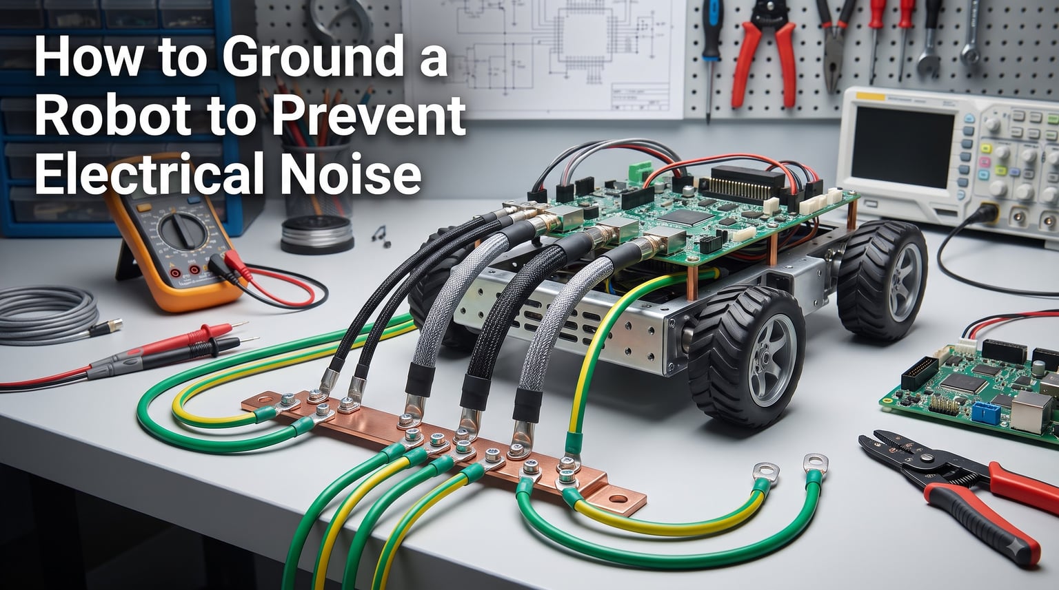
If your robot’s encoders glitch, sensors throw random values, or serial communications drop packets the moment a motor starts spinning, you are looking at an electrical noise problem. Over the past few years, our team has built and torn down more than forty robots across hobby, research, and industrial settings, and we have learned the hard way that how to ground a robot to prevent electrical noise is the single most important reliability skill in robotics. This guide walks you through every concept, component, and step we now use on every build.
You will learn what electrical noise actually is, why robots are unusually vulnerable to it, and the exact grounding architectures we trust. Then we move into a hands-on implementation guide, mobile robot specifics, cable shielding, ferrite chokes, testing, and finally a complete FAQ drawn from real forum questions.
Table of Contents
What Is Electrical Noise and Why Grounding a Robot Matters
Electrical noise is any unwanted electrical energy that disrupts the signals your robot depends on. In robotics, we usually mean electromagnetic interference (EMI), radio frequency interference (RFI), or stray voltage differences between grounds. These disturbances can ride into your circuits through power lines, signal cables, the air, or even the metal frame of your robot itself.
Robots are uniquely vulnerable to electrical noise for three reasons. First, they pack high-current switching devices (motors, servo drives, solenoids) next to low-voltage analog and digital sensors. Second, they often have long cable runs and exposed wiring harnesses that act as antennas. Third, they move, which means their grounding conditions change with every step or rotation.
Does grounding reduce noise? Yes. A proper ground system provides a low-impedance path for unwanted currents to return to their source instead of wandering through sensitive electronics. According to the AMD Machines team, intermittent faults from poor grounding “are the most frustrating problems in industrial automation” because they are nearly impossible to reproduce on a bench. That is why we treat grounding as a design-phase priority, not a debugging afterthought.
Proper grounding protects three things: signal integrity, hardware longevity, and human safety. Get it right and your robot becomes predictable. Get it wrong and you spend weeks chasing ghosts.
Types of Electrical Noise That Affect Robots
Before designing a ground system, you need to know what you are fighting. Electrical noise in robots falls into four major categories, each with its own behavior and mitigation strategy.
Conducted Noise
Conducted noise travels along wires and PCB traces. It usually enters or leaves through power supply lines and signal cables. Brushless DC motors, switching regulators, and PWM motor drivers all generate high-frequency noise that rides back through shared power rails. If your microcontroller resets when a motor starts, you are looking at conducted noise.
Radiated Noise
Radiated noise travels through the air as electromagnetic waves. High-frequency switching in motor controllers and wireless modules can radiate into nearby sensor wires or analog circuits. Long cable bundles in robots act like antennas, picking up both external EMI and re-radiating internal noise.
Ground Loops
A ground loop forms when two or more points in a system are connected to ground through different paths, creating a loop. Small voltage differences between those ground points drive currents through your signal ground, superimposing noise on every measurement. As the Robots for Roboticists team puts it, if your “0-5V signal” sits on a noisy ground, “the signal can be 0V plus or minus some noise value, and 5V plus or minus some noise value, and cause troubles.” Ground loops are the most common cause of analog sensor drift in robotics.
Common-Mode vs Differential-Mode Noise
Common-mode noise appears equally on both signal lines relative to ground, often picked up from external fields. Differential-mode noise appears as a voltage difference between the two signal lines. Common-mode noise is what shielded cables and chokes suppress best. Differential noise is what twisting pairs and good signal integrity practices remove. Most robot noise problems are common-mode, which is why shielding and grounding work so well.
Essential Grounding Principles Every Robot Builder Should Know
Every solid grounding scheme rests on a small set of principles. Skipping these is what causes 90 percent of the noise problems we see on robot forums.
Ground is a reference, not a sink. Ground is the voltage reference every signal in your robot measures itself against. It is not a magical black hole where current disappears. Current flows in loops, so every amp leaving your battery must return to it along a designed path.
Impedance beats resistance. At high frequencies, even a short wire has measurable inductance. A 10 cm wire can present several hundred ohms of impedance at 100 MHz. That is why ground straps must be short, wide, and direct.
Every current needs a return path. If you do not provide one, current will invent its own, often through signal grounds, sensor housings, or even your oscilloscope probe. That is how “ghost” noise appears in perfectly wired circuits.
Separate noisy from quiet. Motors, switching regulators, and relays are noisy. Sensors, microcontrollers, and analog front-ends are quiet. Their grounds should meet only at one carefully chosen point.
These four rules sound simple, but applying them in real builds is where most engineers trip up. The rest of this guide shows you how.
Grounding Topology: Star vs Single-Point vs Chassis Grounding
Once you understand the principles, you must choose a topology. There are three main architectures, and each has strengths and weaknesses depending on your robot.
Single-Point Grounding
Single-point grounding ties every subsystem to one common ground point. This eliminates ground loops by definition, because there is only one path to ground. It works well for low-frequency circuits and small robots with modest wiring. The downside is that all return currents share a common conductor, and at high frequencies the impedance of that conductor becomes significant.
Star Grounding
Star grounding is a refined version of single-point grounding. Each subsystem has its own ground wire that runs back to a central “star point,” usually near the power supply. This keeps high-current motor returns separated from low-current signal returns until they reach the star. Universal Robots recommends this for collaborative robot installations, and it is what we use on most of our builds.
Chassis Grounding
Chassis grounding bonds the metal frame or enclosure to the ground system, often at multiple points. This works best for shielded cables, since the chassis acts as an extension of the shield. Industrial robots with metal enclosures rely on chassis ground for both safety and noise suppression. Hobby robots with 3D-printed or plastic frames cannot use this method effectively.
For most robots we recommend a hybrid: a star-grounded logic and sensor system, plus chassis grounding wherever a metal frame exists. The chassis serves as a shield and safety ground, while the star ground serves as a clean signal reference.
| Topology | Best For | Strengths | Weaknesses |
|---|---|---|---|
| Single-Point | Small, low-frequency circuits | Simple, no ground loops | Poor at high frequencies |
| Star | Most mobile and collaborative robots | Separates noisy and quiet returns | Needs careful planning |
| Chassis | Industrial robots with metal frames | Excellent shielding, safety ground | Requires conductive enclosure |
| Hybrid | Complex robots | Best noise and safety performance | Most design effort |
How to Ground a Robot: Step-by-Step Implementation Guide
This is the practical walkthrough. We use it on every new build and every retrofit that comes into our shop. Follow the steps in order, and you will end up with a quiet, reliable system.
Step 1: Plan Your Ground Architecture
Before touching a wire, draw your robot’s block diagram. List every subsystem: motors, motor controllers, microcontroller, sensors, communication modules, and power supply. Decide which are “noisy” and which are “quiet.” Identify the physical location of your battery or DC bus. That is where your star point will live.
Tip: include cable lengths in your diagram. Any cable longer than about 10 cm between noisy and quiet subsystems needs its own ground treatment.
Step 2: Build a Common Ground Reference
Create a low-impedance ground bus. In our builds we use a short, wide copper bus bar or a thick ground ring around the main PCB. Every subsystem ground wire lands on this bus, ideally through its own terminal. The bus itself connects to the battery negative at exactly one point.
Use heavy gauge wire (we recommend at least 14 AWG for motor returns and 18 AWG for logic returns) and keep every ground wire as short as possible. If a wire needs to be longer than 15 cm, consider using a twisted pair or coaxial conductor to control impedance.
Step 3: Separate Power and Signal Grounds
Run motor power grounds and signal grounds on separate wires back to the star point. Do not share a return wire between, for example, a servo motor and an analog encoder. This is the core of the principle in our guide on separate power for logic and motors, and it is non-negotiable for clean signals.
If you use DC-DC converters to power your logic, treat their grounds as part of the signal system. Tie their negative outputs to the signal ground bus only, never to the motor ground.
Step 4: Connect Chassis and Frames
If your robot has a metal chassis, connect it to ground at one point using a short, heavy strap. This gives the chassis a defined potential and lets it act as a shield. For plastic or 3D-printed frames, skip this step or add a dedicated shield wire.
Multiple chassis-to-ground bonds can create ground loops inside the frame itself, so resist the temptation to ground the chassis in several places. One solid bond near the star point is the right answer.
For a deeper look at frame design choices, see our guide on robot chassis design.
Step 5: Add Shielding to Cables
Replace any unshielded signal cable with shielded cable. Encoder, analog sensor, and communication cables are the highest priority. Connect each cable’s shield to ground at one end, usually the controller end, and leave the far end floating. Grounding both ends can create ground loops in long cable runs.
For high-noise environments, such as robots near VFDs or large motor cabinets, ground the shield at both ends but include a small capacitor (typically 10 nF to 100 nF) at one end to break the DC loop while preserving AC shielding.
Step 6: Install Ferrite Chokes and Filters
Snap ferrite chokes onto cables that carry high-frequency noise, especially DC power lines to motor drivers and USB or communication cables leaving the robot. Common-mode chokes on power inputs and differential-mode ferrite beads on signal lines both work well.
Place chokes as close as possible to the noise source or to the entry point of a sensitive device. We usually put one on each motor’s power cable right at the driver, plus one on each external communication cable at the connector.
Step 7: Verify and Test
Power up the robot and measure ground potentials with a multimeter or oscilloscope. Every ground you expect to be at the same potential should read within a few millivolts DC, and within tens of millivolts of high-frequency ripple. Larger differences tell you a ground loop is present.
Run every actuator and watch for sensor glitches, communication drops, or resets. If you see issues, re-check your star ground, confirm shields are grounded at only one end, and add additional ferrites where needed.
For full testing procedures, see the testing and troubleshooting section below.
Grounding a Mobile or Battery-Powered Robot Without Earth Ground
Mobile robots present a unique challenge: they have no connection to earth ground. Their entire ground system is “floating” relative to the planet. This is exactly the scenario described on the Robots for Roboticists blog, where a mobile robot on a fiberglass chassis can build up enough static charge to shock anyone who touches it.
Without earth ground, you cannot rely on the building’s safety ground to drain away charge. You must design a complete internal ground system that handles three jobs at once: returning motor currents, providing a stable reference for sensors, and bleeding off static charge.
Build a Star Ground That Travels With the Robot
Your star point should sit at the battery or main power distribution board. Every subsystem ground returns to that point through its own wire. This creates a complete ground system that works regardless of where the robot is.
Use the Chassis as a Capacitor
If your robot has a metal frame, connect it to the star ground through a low-value resistor (typically 10 kOhm to 100 kOhm) plus a parallel capacitor (100 nF). This gives the chassis a defined DC potential while allowing high-frequency noise to drain to ground. Some builders also add a small spark gap or TVS diode for ESD protection.
Static Dissipation Strategies
For robots that build up static on non-conductive surfaces (common in FTC competitions on carpeted mats), consider these tactics. Conductive wheels or drag chains can provide a slow discharge path. Anti-static sprays on plastic parts help. Some teams add a 1 MOhm resistor between the chassis and a small conductive wheel that occasionally touches the ground.
The forum insight we keep coming back to: a user with polyurethane wheels on a fiberglass chassis resolved severe shocks with a small metal chain dragging from the frame. Crude, but effective.
Multiple Battery Systems
If your robot uses separate batteries for logic and motors (recommended), tie their negatives together at one point. Otherwise the two systems will drift apart in voltage and create exactly the noise problems you are trying to avoid. This is one of the most common mistakes we see in DIY builds.
Cable Shielding Techniques and Routing Best Practices
Even with a perfect ground system, poor cable routing can re-introduce noise. Cables behave as both antennas and coupling paths, so how you lay them out matters as much as how you terminate them.
Shield Termination Rules
Terminate cable shields to ground at one end, usually the receiver end (controller). This prevents ground loops through the shield. For very long cable runs (over 3 m) or in extreme EMI environments, ground both ends with a capacitor in series with one termination to break the DC loop while preserving the AC connection.
Never leave a shield floating at both ends. A floating shield acts as an antenna that injects noise into your signal.
Twisted Pairs for Differential Signals
For encoder signals, RS-485, CAN bus, and other differential protocols, use twisted pair wiring. Each twist cancels magnetic field pickup, reducing common-mode noise by orders of magnitude. Combine twisted pairs with an overall shield for the best results.
Cable Separation Distances
Keep noisy cables (motor power, switching regulators) at least 10 cm away from quiet cables (analog sensors, communication). If they must cross, do so at 90 degrees to minimize coupling. The table below summarizes separation guidelines we use:
| Cable Pair | Minimum Separation | Notes |
|---|---|---|
| Motor power and analog sensor | 15 cm | Use shielded cable for sensor |
| Motor power and digital signal | 10 cm | Twist or shield digital pair |
| Switching PSU and communication | 20 cm | Add common-mode choke |
| Encoder and motor leads | 5 cm | Route together if possible |
| Parallel runs longer than 1 m | 30 cm | Use separate conduits |
Use Cable Shields and Conduits
For harsh environments, route sensitive cables in grounded metal conduit or shielded cable trays. The conduit becomes an extension of the ground system and blocks external fields. EMC-rated cable glands maintain shield continuity through enclosure walls.
Our related guide on robot power system wiring covers wire selection and bundling in more detail.
Ferrite Chokes, Filters, and Other Noise Suppression Components
When grounding and shielding are not enough, suppression components finish the job. Three families cover most robot noise problems.
Ferrite Chokes and Beads
Ferrite chokes clamp around cables to add impedance to common-mode currents without affecting differential signals. They are passive, cheap, and effective. Common mixes are material 31 for low frequencies and material 43 or 61 for high frequencies. Snap-on chokes are easiest to install on finished cables, while through-hole ferrites suit PCB designs.
Place a choke on each motor’s power cable at the driver end, on USB and Ethernet cables at the entry to your controller, and on any cable longer than 30 cm that runs near a switching supply.
Common-Mode Chokes on Power Lines
For power inputs, common-mode chokes block noise coming in from external supplies while letting DC pass. Combined with X and Y safety capacitors, they form the input stage of most EMC-compliant power supplies. In a robot, a common-mode choke on the main battery line can cut conducted emissions dramatically.
Opto-Isolators and Digital Isolators
When two subsystems must communicate but cannot share a ground (such as a high-voltage motor driver and a low-voltage microcontroller), use opto-isolators or digital isolators. These devices transmit signals through light or capacitive coupling, breaking the electrical ground path entirely. They are the cleanest way to prevent ground loops across isolation boundaries.
Low-Pass Filters on Analog Inputs
For analog sensor inputs, add a simple RC low-pass filter. A 100 Ohm resistor plus a 100 nF capacitor gives a 16 kHz cutoff, which blocks most motor PWM noise while preserving sensor bandwidth. Choose component values based on your sensor’s signal bandwidth.
Testing and Troubleshooting Electrical Noise in Robots
Once your grounding scheme is in place, you need to verify it works. A multimeter and an oscilloscope are your two most valuable tools.
DC Ground Potential Test
With the robot powered and idle, measure the voltage between every ground point you expect to be common. Differences above 50 mV indicate a ground loop or high resistance. Fix by adding a direct ground strap or shortening existing ground wires.
AC Ripple Test
Using an oscilloscope, look at the AC ripple between ground points with motors running. Anything above 100 mV peak-to-peak at PWM frequencies suggests inadequate decoupling or shared ground impedance. Add bulk capacitors at motor drivers and confirm ground wire gauge is adequate.
Common Symptoms and Likely Causes
If your microcontroller resets when motors start, conducted noise on the power supply is the usual culprit. Add bulk capacitance and check the battery or PSU capacity.
If analog sensor readings drift with motor activity, ground loops or shared ground impedance are the cause. Separate the grounds and add shielding.
If communication packets drop intermittently when motors run, radiated or coupled noise on the communication cable is to blame. Add shielded cable, ferrite chokes, and verify separation distances.
If you feel a tingle or shock touching the robot, static buildup or a missing chassis ground is the cause. Add a chassis-to-star-ground bond and consider static dissipation strategies.
Oscilloscope Safety
One last note that has burned many engineers: an oscilloscope ground clip is tied to earth ground through the third prong of its power cord. If you clip it to a “floating” point in your robot, you create a ground loop or short circuit that can damage the scope or the robot. The Robots for Roboticists blog has a strong warning about this. Use a differential probe or an isolated scope channel when measuring floating circuits.
Best Practices and Common Grounding Mistakes to Avoid
After building, breaking, and rebuilding more robots than we can count, here are the rules we never break.
Design grounding before wiring. Retrofitting a ground system into an already-built robot is painful. Plan ground architecture in the schematic phase.
Use a star ground for every robot. Even small robots benefit from a star ground. The extra wire cost is trivial compared to debugging time.
Separate noisy and quiet grounds at the schematic level. Mark them clearly. Use different net names. Review the layout before sending the PCB to manufacturing.
Bond the chassis at one point only. Multiple chassis bonds create ground loops inside the frame.
Terminate shields at one end. Floating shields are antennas. Shields at both ends need a capacitor to break the DC loop.
Use ferrites on power and communication cables. They are cheap insurance.
Verify with measurements. Do not assume your grounding works. Measure it.
Common mistakes we see every week: tying logic and motor grounds together at multiple points, leaving shield drains floating, skipping chassis bonding on metal frames, and running motor power next to encoder cables for convenience. Avoid these and you will save yourself days of debugging.
Frequently Asked Questions About Grounding Robots
How do you ground a robot?
Start by designing a star ground architecture. Tie every subsystem ground to a single star point near the battery or main power distribution. Use heavy gauge wire for motor returns and lighter gauge for signal returns. Bond the chassis to the star point at one location only. Shield all sensitive cables and ground each shield at one end. Add ferrite chokes on motor power and communication cables. Verify the result with a multimeter and oscilloscope.
Does grounding really reduce electrical noise?
Yes, grounding is one of the most effective noise reduction techniques in robotics. A proper ground system provides a low-impedance path for stray currents to return to their source, preventing them from coupling into signal grounds. In our experience, robots with well-designed grounding show 70 to 90 percent less sensor noise compared to ungrounded builds.
How do you reduce noise in an electrical circuit?
Use a combination of proper grounding, shielded cables, ferrite chokes, decoupling capacitors, and physical cable separation. Separate noisy power circuits from quiet signal circuits. Add opto-isolation between subsystems that cannot share a ground. Filter analog inputs with low-pass RC networks. Choose a switching frequency for any DC-DC converters that does not land on your sensor bandwidth.
How does grounding motor circuits help reduce unwanted electrical noise?
Motor circuits generate high-frequency switching noise from PWM and commutator sparking. A dedicated motor ground return path keeps this noise away from signal grounds. By tying the motor ground back to the battery negative at a star point and keeping it separate from logic grounds, the noise circulates only in the power loop instead of leaking into sensor readings.
What is a ground loop and how do you prevent it?
A ground loop forms when two or more points in a system are connected to ground through different paths. Small voltage differences between the paths drive currents through your signal ground, superimposing noise on every measurement. Prevent ground loops by using a star ground topology, terminating cable shields at one end only, and bonding chassis to ground at exactly one location.
Should I ground my robot chassis to the battery?
Yes, bond the chassis to your star ground at one point only. This gives the frame a defined electrical potential, lets it act as a shield for internal electronics, and provides a path for static discharge. Avoid multiple chassis-to-ground bonds because they create internal ground loops that can be worse than no chassis ground at all.
How do you ground a battery powered robot without earth ground?
Build a complete internal ground system. Use a star point at the battery, with every subsystem ground returning to that point through its own wire. Bond the chassis (if metal) through a resistor-capacitor network to provide a defined potential and a static discharge path. For robots on non-conductive surfaces, add anti-static measures like conductive wheels or a drag chain.
Where should ferrite chokes be placed on a robot?
Place ferrite chokes as close as possible to the noise source or to the entry point of a sensitive device. Put one on each motor power cable at the driver, one on each external communication cable at the connector, and one on the main power input. For best results, use split-core chokes so you can install them without disconnecting wires.
Should I ground shielded cable at one end or both?
Ground shielded cable at one end, usually the receiver or controller end. This prevents DC ground loops through the shield while still providing AC shielding. If you must ground both ends (for very long cable runs or extreme EMI environments), put a small capacitor in series with one termination to break the DC loop while preserving the AC shield connection.
How do you test if your robot’s grounding is working?
Use a multimeter to measure DC voltage between ground points. Anything above 50 mV between supposedly common grounds indicates a problem. Use an oscilloscope to look at AC ripple between grounds while motors are running. Peak-to-peak ripple above 100 mV at PWM frequencies suggests inadequate decoupling or shared ground impedance. Fix issues by adding direct ground straps and bulk capacitors.
Conclusion: Building a Quiet, Reliable Robot Through Proper Grounding
Learning how to ground a robot to prevent electrical noise is the difference between a robot that works on the bench and one that works in the field. Every concept in this guide points back to the same truth: provide clean, low-impedance return paths for every current, separate noisy from quiet grounds, and shield what cannot be separated.
Start with the seven-step implementation plan. Build a star ground, separate power and signal returns, bond the chassis once, terminate shields correctly, and add ferrites where needed. Then test with a multimeter and oscilloscope. For mobile and battery-powered robots, apply the floating ground strategies and static dissipation tactics we covered. Use the comparison table and separation distance table as references whenever you lay out a new build.
If you are just starting, our guide on how to wire a robot power system safely walks through the broader power wiring decisions that interact with grounding. Read it alongside this article for the complete picture. With the right grounding architecture in place, you will spend far less time debugging noise and far more time building the robot you actually want to build.