
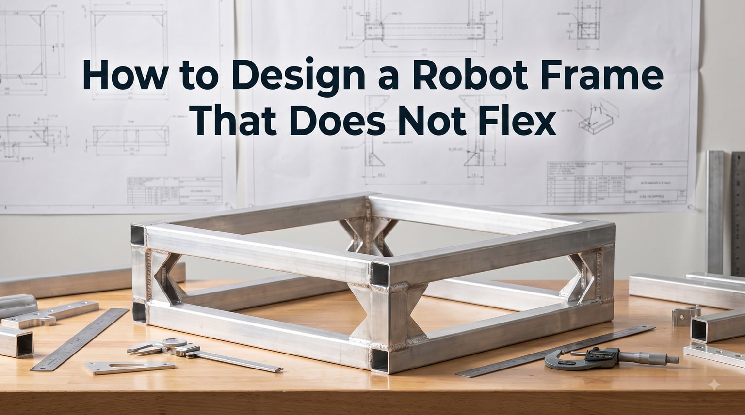
Frame flex is the silent killer of robot performance. You spend weeks tuning PID loops, calibrating sensors, and perfecting your navigation stack, only to discover your robot drifts, wobbles, or veers off course because the chassis bends under load. If you have ever watched your autonomous robot miss its target by inches and suspected the frame, you are probably right.
In this guide, I will walk you through how to design a robot frame that does not flex, covering everything from material selection and structural geometry to joint design and testing methods. Whether you are building a competition combat bot, an autonomous mobile robot, or a precision arm, these principles apply universally.
Our team has spent years building robots and analyzing hundreds of frame failures from forums, competition pits, and lab benches. We compiled the lessons learned here so you can avoid the expensive mistakes we and others have made. If you need a refresher on chassis fundamentals first, check out our guide on robot chassis basics before diving into the advanced anti-flex techniques below.
Table of Contents
Why Frame Flex Is Your Biggest Enemy
Frame flex destroys precision in ways that are hard to diagnose. When your chassis bends even a few millimeters under load, every sensor mounted on it shifts position relative to where the software thinks it is. That tiny shift compounds into large errors over time.
Consider what happens with a LiDAR unit mounted on a frame that flexes by 2 millimeters during acceleration. The scan data now references a slightly different origin point than your odometry expects. Your mapping algorithm stitches together point clouds that are misaligned by that 2 mm offset on every scan. Over a 10-minute autonomous run, those errors accumulate into drift that can reach tens of centimeters.
IMU sensors suffer the same fate. A flexible frame introduces vibrations and angular deviations that the IMU picks up as real motion. Your Kalman filter cannot distinguish between actual robot rotation and frame-induced sensor wobble. The result is degraded localization that gets worse the longer the robot runs.
Forum discussions on r/robotics and Robotics Stack Exchange repeatedly highlight this problem. Builders report that a drive base lacking rigidity produces unpredictable movement and makes the robot difficult to control. Experienced engineers emphasize that stiffness matters more than raw strength for most applications because small deflections cause outsized accuracy problems.
Frame flex also causes mechanical wear. When the chassis bends, shafts no longer align with bearings, gears mesh incorrectly, and motors experience side loads they were not designed for. Over time, this causes premature failure of gearboxes, bearings, and motor shafts. Many builders discover frame problems only when components start failing prematurely.
Understanding What Causes Frame Flex
Frame flex occurs when applied forces exceed the structural stiffness of your frame. The physics comes down to material properties and structural geometry working together. Understanding both helps you design frames that resist bending from the start.
Young’s modulus is the fundamental property at play. It measures a material’s resistance to elastic deformation under stress. Aluminum 6061-T6 has a Young’s modulus of about 69 GPa, while mild steel sits around 200 GPa. That means steel is roughly three times stiffer than aluminum for the same cross-section. But stiffness is not just about the material.
Flexural stiffness combines material properties with geometric properties. The moment of inertia of your frame’s cross-section determines how well it resists bending. A box section with the same wall thickness and weight as a flat plate can be 50 to 100 times stiffer because the material is distributed farther from the bending axis. This is why flat plates flex badly while tubes and box sections hold firm.
Load distribution matters too. A concentrated load in the center of a frame span creates far more deflection than the same load distributed across the structure. Heavy batteries, manipulator arms, and payload compartments need strategic placement near frame supports, not in the middle of unsupported spans.
Finally, joint compliance contributes to flex. Even with rigid materials and good geometry, loose or poorly designed joints introduce compliance that can exceed the flex of the frame material itself. Many builders report their frames failing at bolted joints rather than in the material. I have seen this firsthand, and it is why joint design deserves as much attention as material selection.
How to Design a Robot Frame That Does Not Flex: Core Principles
Designing a rigid frame is a systematic process. Follow these steps to build a chassis that holds its shape under real-world loads.
Step 1: Define your load cases. List every force the frame will experience: robot weight, payload, battery mass, acceleration forces, collision impacts, and manipulation loads. For a competition robot, include worst-case collision forces. For an autonomous mobile robot, factor in payload shifts during braking and acceleration.
Step 2: Choose closed cross-sections over open ones. Box sections, round tubes, and square tubes resist bending and torsion far better than flat plates, L-brackets, or channel sections. The closed shape distributes material efficiently around the bending axis. If you must use open sections, combine them back-to-back to create a pseudo-closed profile.
Step 3: Design with triangulation. Truss structures use triangles to distribute loads along member axes rather than across bending planes. A frame with diagonal cross-bracing transfers forces through tension and compression rather than bending. This is why truss designs achieve high stiffness at low weight.
Step 4: Minimize unsupported spans. Every inch of unsupported frame member is a potential flex point. Add intermediate supports, cross-members, or ribs under heavy components. A battery sitting on a 400 mm unsupported span will deflect that span. The same battery on a 150 mm span with end supports barely moves it.
Step 5: Use gussets at every joint. Gussets are reinforcement plates bolted or welded at frame intersections. They increase the joint’s moment of inertia and prevent rotation at the connection point. A simple triangular gusset plate at each corner can reduce frame flex by 30 to 50 percent compared to an ungusseted frame.
Step 6: Plan your mounting points. Mount sensors, motors, and actuators directly to frame nodes where members intersect. Nodes are the stiffest points in any frame structure. Mounting on the middle of a beam span guarantees the component will move when the beam flexes.
Step 7: Account for thermal effects. Different materials expand at different rates. If you combine aluminum and steel in the same frame, temperature changes introduce stress that can warp the structure. For precision applications, use materials with similar thermal expansion coefficients or design expansion joints.
Choosing the Right Material for Maximum Rigidity
Material selection is the single biggest decision in frame design. Each material offers a different balance of stiffness, weight, cost, and manufacturability. Here is how the main options compare.
Aluminum 6061-T6 is the most popular robot frame material for good reason. It offers a Young’s modulus of 69 GPa, weighs one-third as much as steel, machines easily, and welds cleanly. For most robotics applications, 6061-T6 provides the best stiffness-to-weight ratio at a reasonable cost. Extruded aluminum profiles with T-slots are convenient for prototyping but sacrifice some rigidity compared to welded or bolted box sections.
Mild steel has a Young’s modulus of roughly 200 GPa, making it three times stiffer than aluminum. For heavy-duty robots carrying large payloads or absorbing collision impacts, steel provides excellent rigidity. The downside is weight and corrosion risk. Steel frames work well for combat robots, industrial platforms, and stationary manipulators where weight is less critical than stiffness.
Stainless steel offers the same stiffness as mild steel with corrosion resistance. It is harder to machine and weld, making it more expensive. Choose stainless for robots operating in wet, chemical, or food-processing environments where corrosion would compromise frame integrity.
Carbon fiber composites deliver exceptional stiffness-to-weight ratios. A carbon fiber tube can match the stiffness of steel at one-fifth the weight. However, carbon fiber is expensive, requires specialized manufacturing, and fails catastrophically rather than yielding. It is ideal for competition drones and high-performance robots where budget allows and weight savings matter.
3D printed materials work for prototyping but rarely provide sufficient stiffness for final designs. PETG, ABS, and nylon printed frames typically flex far more than metal alternatives. If you prototype with 3D printing, plan to replace critical structural members with machined aluminum or steel for the final build.
For beginners choosing their first frame material, aluminum 6061-T6 box section is almost always the right answer. It is affordable, available in standard sizes, easy to work with, and stiff enough for most applications. As you move to heavier payloads or higher precision requirements, steel and composites become worth the investment. When integrating electrical systems with your metal frame, be sure to review power system safety and grounding to avoid short circuits and interference.
Joint Design and Fastening Methods That Hold Tight
Joints are where most frames fail. The material between joints rarely flexes enough to cause problems, but the connections between members introduce compliance that accumulates across the frame. Get your joints right and most flex problems disappear.
Welding creates the stiffest possible joint because it fuses members into a single continuous piece. TIG welding aluminum and MIG welding steel produce joints that match or exceed the stiffness of the parent material. The trade-off is permanence: once welded, you cannot adjust or disassemble the joint. Welded frames require accurate cut dimensions because there is no room for error correction during assembly.
Welded box sections dramatically outperform bolted aluminum extrusions for stiffness. Forum users on r/robotics frequently report that upgrading from bolted extrusion frames to welded box sections transformed their robot’s stability. If your design is finalized and weight allows, welding is the gold standard.
Bolting offers flexibility, reparability, and ease of assembly. The challenge is maintaining joint stiffness over time. Bolted joints loosen under vibration, especially on robots that accelerate hard or experience impacts. Use these techniques to keep bolted joints rigid: grade 8 or higher hardware, nyloc nuts or thread-locking adhesive, conical spring washers, and torque to specification on every fastener.
Design bolted joints with shear loading rather than tension loading wherever possible. A bolt in shear resists lateral forces through the bolt shank, while a bolt in tension relies on clamping force that can relax over time. Use dowel pins to locate components precisely and reduce the load on bolts.
Adhesive bonding works for lighter loads and composite materials. Structural epoxy adhesives can create joints nearly as stiff as welds while distributing stress over a larger area. Bonding is ideal for carbon fiber frames where welding is impossible. However, adhesive joints are sensitive to surface preparation, temperature, and cure time. Always test bonded joints under load before trusting them in a robot.
Many builders combine methods. They weld the primary frame structure for maximum stiffness and use bolted joints for removable panels and access covers. This hybrid approach gives you the rigidity of welding where it matters most and the serviceability of bolting where you need access. When mounting high-torque components like gearboxes to your frame, the joint design becomes even more critical. Our guide on gearbox mounting and integration covers this topic in depth.
Reinforcement Techniques for Existing Frames
Sometimes you already have a frame that flexes and need to stiffen it without a complete redesign. Several reinforcement techniques can dramatically improve an existing frame’s rigidity.
Add gussets to every joint. This is the highest-return reinforcement you can make. Cut triangular plates from aluminum or steel and bolt or weld them at each frame intersection. A gusset that extends about one-third of the member length along each side provides excellent stiffness improvement. This single change can reduce frame flex by 30 to 50 percent.
Install cross-members. If your frame has long unsupported spans between rails, add cross-members perpendicular to the main frame direction. These create shorter, stiffer spans and help distribute loads across the structure. Position cross-members under heavy components like batteries and motor mounts.
Add diagonal bracing. Diagonal members convert bending loads into axial loads along the brace. Even a single diagonal in each rectangular frame bay dramatically increases torsional rigidity. Use steel cable, round tubing, or flat bar for diagonal bracing depending on your load requirements.
Apply ribbing to flat panels. Flat plates flex badly under load, but adding ribs transforms them into stiff structures. Glue or bolt aluminum angle stock to the back of flat panels in a grid pattern. The ribs increase the effective moment of inertia without adding much weight.
Upgrade to thicker material. Doubling wall thickness can reduce deflection by up to 75 percent in some geometries because stiffness scales with the cube of thickness. This adds weight, but for robots where weight is not the primary constraint, thicker material is the simplest path to a stiffer frame.
For hobbyists on a budget, these reinforcement techniques deliver the best value. Forum builders report that gussets and cross-members made from scrap aluminum angle stock transformed wobbly frames into solid platforms for under $20 in materials. The key is targeting the joints and spans where flex is most visible.
Design Verification and Testing
Designing a rigid frame is only half the battle. You need to verify that your design actually achieves the stiffness you intended before committing to manufacturing. Two approaches dominate: computational analysis and physical testing.
Finite Element Analysis (FEA) simulates how your frame will deform under load before you build it. Modern FEA tools like SolidWorks Simulation, ANSYS, and even free options like Fusion 360’s built-in solver let you identify weak points in your design digitally. The basic workflow involves importing your CAD model, applying material properties, defining fixed supports, applying loads, and running the solver to produce a deflection map.
A practical FEA workflow for robot frames starts with a simplified model. Remove non-structural features like holes and fillets that complicate meshing. Apply realistic boundary conditions that match how the frame will actually be supported. Use your defined load cases from the design phase. Run a linear static analysis first to identify maximum deflection locations, then refine the mesh in those areas for accuracy.
FEA has limitations. It assumes perfect joints, ideal materials, and simplified boundary conditions. Real frames have weld imperfections, loose bolts, and material variations that FEA cannot predict. Use FEA to compare design alternatives and catch obvious problems, but always validate with physical testing.
Physical load testing confirms your design in the real world. The simplest approach is incremental load testing. Place the frame on rigid supports, apply known weights incrementally, and measure deflection at critical points with a dial indicator or digital caliper. Plot load versus deflection to verify the frame behaves as expected within the linear elastic range.
Test with incremental loads rather than going straight to full payload. This approach, recommended by experienced builders on robotics forums, reveals problems early. If deflection increases non-linearly or does not return to zero when load is removed, you have identified a problem before it causes catastrophic failure.
Vibration testing reveals resonance issues that static analysis misses. Strike the frame with a mallet and measure how it rings. A well-designed rigid frame produces a high-pitched, short-duration ring. A flexible frame produces a low-pitched, long-duration wobble. Accelerometers and spectrum analyzers give quantitative data, but even a simple listen tells you a lot.
For teams without FEA software, 3D printing scaled frame models offers a quick validation path. Print a simplified version of your frame at reduced scale, apply proportional loads, and observe where flex occurs. The absolute numbers will not match the real frame, but the relative stiffness between design alternatives will be valid.
Common Mistakes to Avoid
After analyzing hundreds of frame failures from forums and competitions, several patterns emerge. Avoid these mistakes and your frame will outperform most builds.
Using flat plates instead of box sections. This is the most common mistake among beginners. Flat plates look simple and are easy to work with, but they flex badly under any load. One forum builder described it perfectly: using flat plates instead of box sections or trusses leads to unexpected flex under load. Always choose closed sections for primary frame members.
Underdesigning joints. Many builders focus on material selection and geometry but treat joints as an afterthought. Joints are where frames fail. A frame made from rigid material with undersized bolts, missing gussets, and poorly aligned holes will flex at every connection. One experienced builder noted that their frames consistently failed at bolted joints rather than in the material itself.
Ignoring weight distribution. Poorly distributed loads create localized stress points that cause concentrated flex. A 20 kg battery mounted in the center of an unsupported frame span will deflect that span significantly. Distribute heavy components near frame nodes and supports, not in the middle of open spans.
Overlooking fastener loosening. Vibration from motors, drivetrains, and collisions loosens bolts over time. Many builders report frames that were stiff when new but developed increasing flex after weeks of operation. Use nyloc nuts, thread-locking compound, and proper torque specification on every fastener.
Skipping prototype testing. Building a complete robot without testing the frame first is a gamble. Forum users who ignored frame rigidity early in design often had to redesign entire systems when sensors started failing. Always test your frame design with a prototype or FEA before committing to the full build.
Choosing stiffness for the wrong reason. Some builders chase maximum stiffness without considering the trade-offs. An over-built steel frame may be rigid but too heavy for the motors to drive efficiently. Balance stiffness against weight, cost, and performance requirements for your specific application.
FAQs
Can a bent chassis be straightened?
A bent chassis can sometimes be straightened depending on the material and severity. Aluminum frames often crack when bent back, so replacement is safer. Steel frames can be straightened using hydraulic presses and heat treatment, but the repaired area may have reduced strength. For precision robots, replacing the frame is usually better than attempting repairs because even slight residual deformation causes ongoing accuracy problems.
How to design a robot chassis?
Design a robot chassis by defining your load requirements, choosing a rigid material like aluminum 6061-T6 or steel, using closed cross-sections such as box tubing instead of flat plates, adding gussets at every joint, and mounting components at frame nodes. Run finite element analysis to verify stiffness, then build a prototype and test with incremental loads before final assembly.
What metal is best for robots?
Aluminum 6061-T6 is the best metal for most robot frames because it offers an excellent balance of stiffness, weight, cost, and machinability. Steel is better for heavy-duty robots requiring maximum rigidity. Stainless steel suits corrosive environments, and carbon fiber composites work for ultra-lightweight high-performance applications.
What is stiffness in robotics?
Stiffness in robotics refers to a frame or component’s resistance to deformation under applied force. It is determined by the material’s Young’s modulus and the geometric properties of the cross-section, specifically the moment of inertia. Higher stiffness means less deflection under load, which translates to better sensor accuracy and more predictable robot behavior.
How does a robot’s stiffness affect its performance?
Frame stiffness directly affects sensor accuracy, navigation precision, and mechanical reliability. Flexible frames cause sensor misalignment, odometry drift, mapping errors, and premature component wear. Even a few millimeters of frame deflection can introduce centimeters of position error over time, making autonomous navigation unreliable and control systems unstable.
Should I weld or bolt my robot frame?
Welding creates the stiffest joints and is best for finalized frame designs where disassembly is not needed. Bolting allows for adjustments, repairs, and modular construction but requires proper hardware, thread-locking compound, and regular maintenance to maintain stiffness. Many builders weld the primary structure and bolt removable panels and access covers.
Conclusion
Designing a robot frame that does not flex comes down to three pillars: choosing the right material, using closed cross-sections and triangulated geometry, and building joints that hold their stiffness over time. When you combine aluminum 6061-T6 or steel box sections with gusseted joints and proper component mounting, you get a chassis that holds its shape under real-world loads.
The most important takeaway is that stiffness is not just about material strength. A frame made from rigid steel with flat plates and loose bolts will flex more than a frame made from aluminum with box sections and welded joints. Geometry and joint design matter as much as material choice.
Start your next frame design with a clear load case analysis. Choose closed sections over flat plates. Add gussets at every joint. Mount critical sensors at frame nodes. Run FEA or build a prototype before committing to the full build. Test with incremental loads. These steps will save you from the expensive failure mode of discovering frame flex only after your robot starts drifting off course.
If you apply these principles, you will build robots that hold their calibration, navigate precisely, and survive the forces they encounter in the field. That is what learning how to design a robot frame that does not flex is all about.