
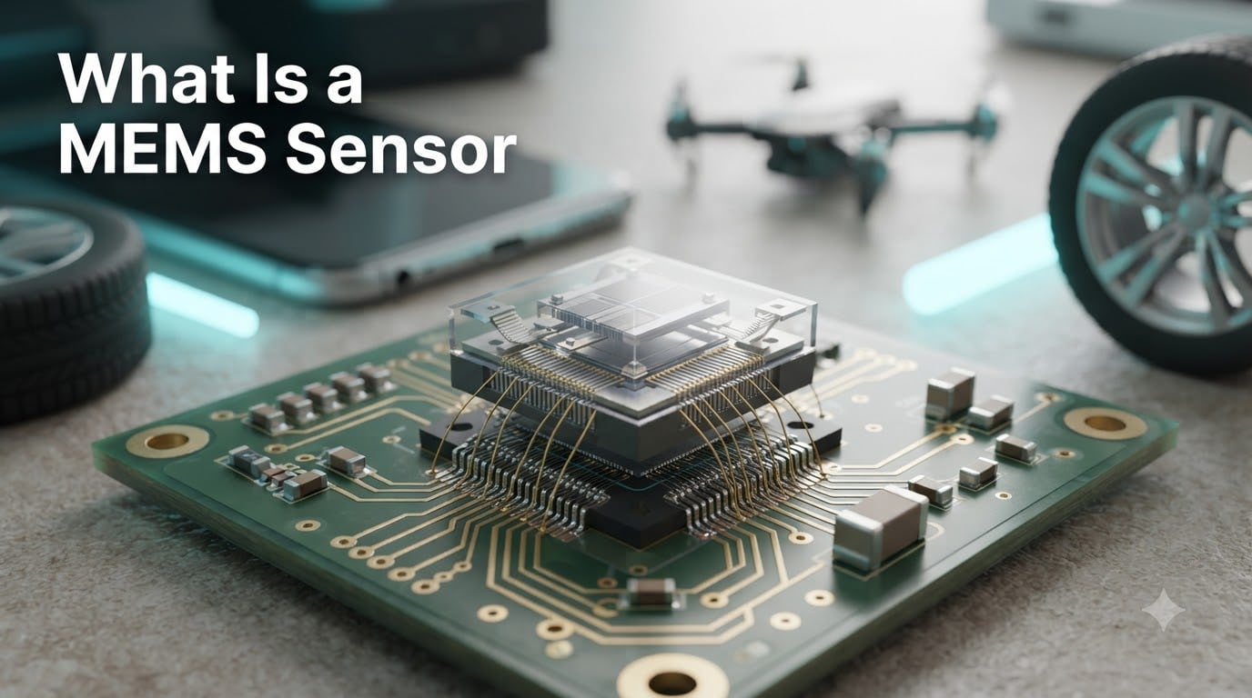
If you have ever wondered how your smartphone knows which way is up, how a car detects a collision in time to fire an airbag, or how a fitness tracker counts your steps, the answer is almost always the same: a MEMS sensor. In this guide, I will walk you through what a MEMS sensor is, how it works on a microscopic scale, the most common types, and where this silicon-chip technology shows up in the devices you use every day.
A MEMS sensor is a microscopic device that combines mechanical moving parts and electronic circuits on a single silicon chip to measure physical changes and convert them into electrical signals. The acronym stands for micro-electromechanical system, and over the past 40 years these tiny machines have quietly become one of the most important building blocks of modern electronics.
By the end of this article, you will understand the working principle behind every MEMS sensor, the four most common variants, the real difference between MEMS and traditional sensors, and the limitations engineers still wrestle with on the lab bench.
Table of Contents
What Is a MEMS Sensor? A Direct Definition
A MEMS sensor is a miniaturized device, usually between 1 and 100 micrometers in size, that integrates mechanical elements like beams, membranes, cantilevers, and suspended masses with electronic circuits on the same silicon chip. When an external physical stimulus such as acceleration, pressure, rotation, or sound moves those mechanical structures, the change is converted into a measurable electrical signal by a built-in application-specific integrated circuit, or ASIC.
Think of a MEMS sensor as a tiny machine plus a tiny computer living on the same piece of silicon. The machine part detects motion, force, or pressure, and the computer part reads what the machine is doing and outputs a clean digital or analog value to your phone, car, or robot.
Two terms deserve quick definitions before we go deeper. MEMS itself is short for micro-electromechanical systems, the broader technology category. A MEMS sensor is the specific device that uses that technology to measure something in the physical world. In industry shorthand, engineers also call these devices micromachines or microsystems.
MEMS sensors are batch-fabricated using the same photolithographic processes used to make computer chips, which is why millions of them can be produced in a single factory run at very low per-unit cost. That combination of microscopic size, low power draw, and economies of scale is what made the smartphone revolution possible.
How Does a MEMS Sensor Work?
MEMS sensors work through a three-stage process. A physical stimulus moves a microscopic structure, that movement changes an electrical property, and an on-chip circuit converts the change into a readable signal. Each stage happens in fractions of a millisecond, which is why these sensors can sample motion or pressure thousands of times per second.
Let me walk you through each stage using a MEMS accelerometer as the example, since it is the most common variant on the market.
Stage 1: Sensing – The Microscopic Structure Moves
At the heart of every MEMS sensor sits a proof mass, a tiny block of silicon suspended by flexible beams or cantilevers. When the device experiences acceleration, the proof mass lags behind due to inertia and shifts a few nanometers relative to the rest of the chip. The beams flex, the gap between the mass and nearby surfaces changes, and that physical deflection is the raw measurement.
For a MEMS pressure sensor, the same idea applies to a thin silicon membrane. External pressure bends the membrane slightly, and that bend is the signal we want to measure. For a MEMS microphone, sound waves push against a flexible diaphragm.
Stage 2: Transduction – Movement Becomes Electricity
Once the structure moves, the sensor needs a way to translate that physical deflection into an electrical quantity. There are three main transduction methods used in MEMS sensors today.
Capacitive transduction is the most common. The moving proof mass and a fixed plate form a tiny capacitor. When the gap between them changes, the capacitance changes in a predictable way, and the on-chip circuit can read that change with extreme precision.
Piezoresistive transduction uses materials whose electrical resistance changes when they are stretched or compressed. MEMS pressure sensors in tire monitoring systems and medical devices often use this method because it is rugged and simple.
Piezoelectric transduction generates a small voltage when certain crystals are mechanically stressed. MEMS gyroscopes and ultrasonic sensors frequently use piezoelectric materials because they respond extremely fast.
Stage 3: Processing – The ASIC Outputs a Clean Signal
The raw electrical change from stage two is tiny and noisy, so it is fed into an application-specific integrated circuit, or ASIC, that lives on the same die. The ASIC amplifies the signal, filters out noise, applies temperature compensation, and converts the result into a standardized output such as an I2C or SPI digital value.
This integration is what makes MEMS sensors so practical. A designer can drop a single 3 mm by 3 mm package onto a circuit board, write a few lines of driver code, and get calibrated, temperature-compensated readings without designing any analog front end.
Common Types of MEMS Sensors
There are four MEMS sensor families you will encounter in nearly every consumer, automotive, and industrial product. Each one measures a different physical quantity using a variation of the three-stage process above.
MEMS Accelerometers
MEMS accelerometers measure linear acceleration along one, two, or three axes. The proof mass shifts when the device accelerates, capacitive plates read the shift, and the ASIC outputs g-force values. Smartphones use them for screen rotation, fitness bands use them to count steps, and cars use them to detect crashes and trigger airbags within milliseconds.
MEMS Gyroscopes
MEMS gyroscopes measure angular rotation. They work by driving a small proof mass back and forth at a known frequency; when the device rotates, the Coriolis force deflects the moving mass sideways, and capacitive sensors detect that deflection. Drones, robotics, and image stabilization systems all depend on MEMS gyroscopes for stable flight and steady video.
MEMS Pressure Sensors
MEMS pressure sensors use a thin silicon diaphragm that flexes under external pressure. The flex changes a piezoresistive or capacitive element, and the ASIC reports pressure in pascals or psi. These sensors show up in tire pressure monitoring systems, blood pressure cuffs, weather stations, and industrial process control equipment.
MEMS Microphones
MEMS microphones have largely replaced traditional electret condenser microphones in phones, laptops, and hearables. Sound waves push against a flexible diaphragm, and the movement is read capacitively. The result is a tiny, surface-mount microphone that can be reflow-soldered onto a circuit board along with all the other components.
Beyond these four, the MEMS family keeps growing. You can now buy MEMS magnetometers, humidity sensors, gas sensors, microfluidic chips for DNA analysis, RF switches for 5G, and even micromirror arrays for projection displays.
Who Invented MEMS Technology? A Brief History
MEMS technology was invented in the early 1980s, and the credit is shared across several research groups working in parallel. The earliest micromachined silicon pressure sensors and inkjet nozzle arrays were demonstrated in the late 1970s, and the term MEMS itself was coined by Professor Kurt Petersen in a 1982 IEEE article that became the founding reference for the field.
By the mid-1980s, companies like Analog Devices, Bosch, and Texas Instruments had begun commercializing the first MEMS accelerometers for automotive airbag systems. The airbag market proved the technology at scale, and once the silicon fabrication processes matured, costs dropped enough for consumer electronics to adopt MEMS in the 2000s.
The introduction of the iPhone in 2007 with a built-in MEMS accelerometer, gyroscope, and microphone is widely considered the moment MEMS went mainstream. Today, a single mid-range smartphone contains between 5 and 15 MEMS sensors.
Where Are MEMS Sensors Used? Real-World Applications
MEMS sensors are used in smartphones, automobiles, wearables, medical devices, industrial equipment, and drones. Anywhere a device needs to sense motion, orientation, pressure, or sound in a small, low-power package, you will find MEMS inside.
Let me break down the biggest application areas our team tracks.
Consumer Electronics and Smartphones
Every modern smartphone contains a 6-axis or 9-axis inertial measurement unit built from a MEMS accelerometer, gyroscope, and magnetometer. Add a MEMS microphone, a barometric pressure sensor for altitude, and sometimes a gas sensor, and you have between 5 and 15 MEMS devices in your pocket. Image stabilization in phone cameras also depends on MEMS gyroscopes running at several kilohertz.
Automotive Safety and Control
Automotive was the first mass market for MEMS and remains one of the largest. Electronic stability control, airbag deployment, anti-lock braking, tire pressure monitoring, and electronic suspension all rely on MEMS sensors. A single car can contain 50 or more MEMS devices, and the number is rising as advanced driver assistance systems become standard.
Wearables and Fitness
Fitness bands and smartwatches use MEMS accelerometers to count steps, detect workouts, and monitor sleep. Pair an accelerometer with a MEMS optical heart-rate sensor and a barometer, and the device can estimate elevation, calories burned, and even stress levels.
Medical and Healthcare
Medical MEMS applications include disposable blood pressure sensors, infusion pump pressure monitors, hearing aids with MEMS microphones, and lab-on-a-chip devices that analyze tiny fluid samples. Implantable devices like cochlear implants and continuous glucose monitors also rely on miniaturized sensors to keep their size and power budget small.
Industrial Monitoring and IoT
Industrial IoT deployments use MEMS vibration sensors on motors and pumps to predict failures before they happen. A wireless sensor bolted to a bearing can detect subtle vibration signatures that indicate wear, which lets maintenance teams replace parts during planned downtime instead of after a breakdown.
Drones and Robotics
Quadcopters, humanoid robots, and autonomous vehicles all need inertial measurement units built from MEMS sensors. Our team has flown research drones that use a 9-axis MEMS IMU running at 1 kHz, and the data is good enough for stable hover and waypoint navigation in moderate wind.
MEMS vs Non-MEMS Sensors: Key Differences
The main difference between MEMS and non-MEMS sensors is size, power consumption, and integration. MEMS sensors put the mechanical element and the readout electronics on the same silicon die, while traditional sensors often have a separate mechanical assembly and signal conditioner. This integration trades some absolute accuracy for dramatic gains in size, cost, and power.
For many applications, MEMS is the obvious winner. For others, traditional quartz accelerometers, fiber optic gyroscopes, or bulky pressure transducers still hold the precision crown. Here is how the two families compare across the dimensions engineers care about most.
MEMS sensors win on size, power, cost, and shock tolerance. A MEMS accelerometer can be 3 mm square and run on microamps of current, while a traditional servo accelerometer might weigh kilograms and need watts of power. MEMS devices are also far more rugged, because the moving parts are so small that they can absorb shocks that would destroy a larger mechanism.
Traditional sensors still win on long-term stability, noise floor, and absolute accuracy. A high-end quartz inertial sensor will outperform a MEMS device in a strategic missile or a deep-space mission. For most commercial applications, though, MEMS performance has improved to the point where it is more than good enough.
Forum discussions on communities like the STMicroelectronics user forum confirm this trade-off. Hobbyists and commercial designers choose MEMS for nearly everything, while aerospace and defense users still pay the size and power penalty for non-MEMS precision when the mission requires it.
Advantages of MEMS Technology
The five biggest advantages of MEMS sensors are miniaturization, low power consumption, batch production, low cost, and high sensitivity. Together these advantages are why MEMS has displaced older sensor designs in almost every mass-market product.
Miniaturization is the headline benefit. A complete MEMS sensor package with mechanical element, ASIC, and digital interface can be smaller than a grain of rice, which lets designers add sensing to products where it was previously impossible.
Low power consumption matters for battery-powered devices. Many MEMS sensors draw less than 1 microamp in sleep mode and only wake the main processor when an event occurs, which is how a fitness tracker can run for weeks on a small coin cell.
Batch production is what makes MEMS affordable. Because MEMS devices are made on silicon wafers using photolithography, a single 200 mm wafer can yield thousands of sensor dies, and per-unit cost drops into the cents range for high-volume parts like smartphone accelerometers.
High sensitivity and low noise come from the extremely small proof masses, which respond to tiny forces and accelerations. Combined with on-chip ASIC amplification, modern MEMS devices can resolve signals that would have been lost in the noise floor of older designs.
Limitations and Challenges of MEMS Devices
The main limitations of MEMS sensors are limited dynamic range, temperature sensitivity, packaging constraints, and long-term drift. These are not deal-breakers, but they are the trade-offs engineers design around in safety-critical or high-precision applications.
Limited dynamic range is the classic problem. A MEMS accelerometer optimized for high-g events like crashes cannot simultaneously measure very low-g motion like tilt drift, and vice versa. Designers must pick the right g-range for the application, or accept lower resolution across the full scale.
Temperature sensitivity affects every MEMS sensor because silicon’s mechanical properties change with temperature. The good news is that the on-chip ASIC includes compensation tables, but residual error still exists and matters in high-precision work like inertial navigation.
Packaging constraints can be a hidden challenge. The moving parts of a MEMS sensor cannot be hermetically sealed in the same way as a standard IC, so manufacturers use specialized caps that protect the structure while letting it move. For some harsh-environment applications, like downhole oil and gas monitoring, even the best MEMS packaging struggles.
Long-term drift is the last big limitation. Over years of use, the calibration of a MEMS sensor can shift slightly, which is why critical applications like aerospace inertial reference units still rely on periodic recalibration or non-MEMS technologies.
Forum users on Reddit and the STMicroelectronics community have also flagged sourcing and integration challenges. Specific MEMS parts can be hard to find outside major distributors, and physically isolating the sensor from board stress is a real design problem that beginners often overlook.
Future Trends in MEMS Sensors
The future of MEMS sensors is heading toward smaller die sizes, lower power budgets, on-chip AI inference, and new applications in healthcare and energy. Several emerging areas are worth watching.
Edge AI is the biggest shift. New MEMS sensors integrate tiny machine learning cores that can classify motion patterns on the device itself, without waking the main processor. Imagine a fitness band that recognizes 50 different exercises using only the accelerometer, with no cloud connection required.
Energy harvesting is closing the loop. MEMS vibration sensors paired with piezoelectric energy harvesters can power themselves from the very motion they are measuring, which opens the door to truly wireless sensor nodes for industrial monitoring and smart agriculture.
Biomedical MEMS is expanding fast. Microneedle arrays for painless drug delivery, microfluidic chips for at-home diagnostics, and swallowable pill cameras with MEMS stabilization are moving from research labs into commercial products. Our team expects this segment to grow faster than consumer electronics over the next five years.
RF MEMS for 5G and 6G is another area to watch. Micromechanical switches and tunable capacitors can outperform solid-state RF components in some metrics, and they are now appearing in antenna tuning modules and millimeter-wave test equipment.
Frequently Asked Questions
How do MEMS sensors work?
MEMS sensors work through three stages. First, a microscopic structure like a suspended proof mass or a flexible diaphragm moves when exposed to a physical stimulus such as acceleration, pressure, or sound. Second, that movement changes an electrical property such as capacitance, resistance, or voltage, a process called transduction. Third, an on-chip application-specific integrated circuit (ASIC) reads the change, amplifies it, and outputs a clean digital or analog signal to the host system.
Can you give me an example of a MEMS device?
Yes. Common examples of MEMS devices include the accelerometer inside a smartphone that rotates the screen, the gyroscope in a drone that keeps it stable in flight, the pressure sensor in a car tire that warns you about low pressure, and the microphone in a laptop that picks up your voice. Medical examples include disposable blood pressure sensors and lab-on-a-chip devices that analyze fluid samples. RF MEMS switches in 5G antennas and micromirror arrays in projectors are also MEMS devices.
Who invented MEMS technology?
MEMS technology emerged in the late 1970s and early 1980s from research groups working on silicon micromachining. The term MEMS itself was coined by Professor Kurt Petersen in a 1982 IEEE article that became the founding reference for the field. Early commercial MEMS pressure sensors and accelerometers were produced in the mid-1980s, and the technology went mainstream when smartphones started using MEMS accelerometers, gyroscopes, and microphones in the 2000s.
What are the limitations of MEMS devices?
The main limitations of MEMS devices are limited dynamic range, temperature sensitivity, packaging constraints, and long-term calibration drift. Because the moving parts are extremely small, MEMS sensors struggle with very large or very tiny signals at the same time. They also require specialized packaging that protects the mechanical structure while still allowing it to move, which adds cost and limits use in some harsh environments.
Final Thoughts on MEMS Sensors
A MEMS sensor is a microscopic machine plus a microscopic computer living on the same silicon chip, and that simple idea powers the screen rotation on your phone, the stability of your drone, and the airbag in your car. Now that you understand the three-stage working principle, the four major sensor families, and the trade-offs MEMS still faces, you have a solid foundation for choosing the right part on your next project.
If you are starting a new design, pick a MEMS sensor from a major manufacturer like Bosch, STMicroelectronics, or Analog Devices, read the application note on mechanical isolation, and budget time for the small but important packaging and stress-relief decisions. MEMS sensors are mature, well-supported parts, and the community around them is large enough that almost any integration problem you hit has already been solved by someone else.