
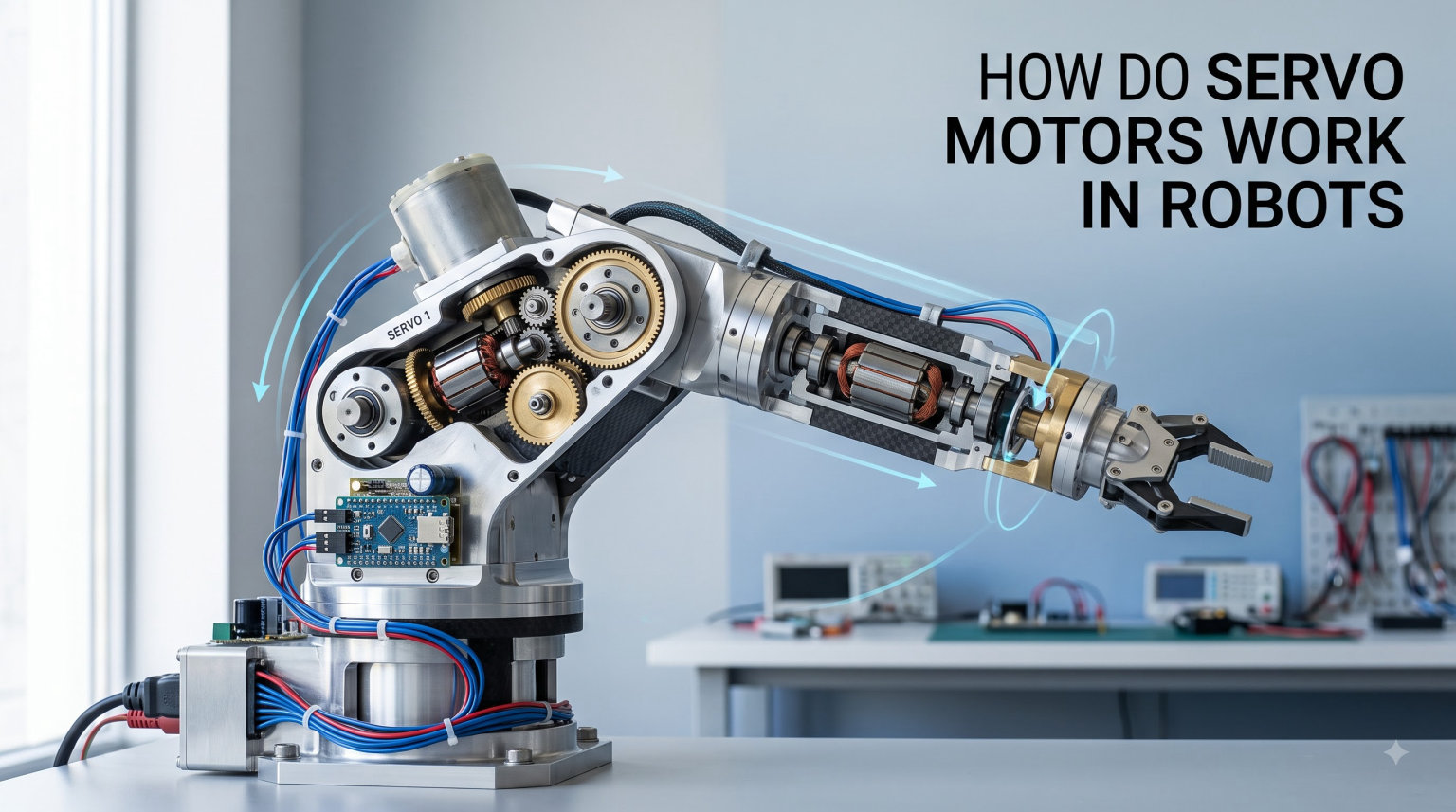
If you have ever wondered how do servo motors work in robots, you are in the right place. A servo motor is the tiny muscle that lets a robot arm bend at a precise angle, keeps a drone’s camera perfectly level, and turns the wheels on an RC car with exact rotations. I have spent the last decade building robots with my team, and servos remain one of the first components we reach for when we need controlled, repeatable motion. In this guide, I will walk you through what a servo motor is, how it works step by step, the parts inside it, the different types you will meet, and how to integrate one with an Arduino. By the end, you will understand why servos are the workhorses of hobby and industrial robotics alike.
Table of Contents
What Is a Servo Motor
A servo motor is a rotary actuator that uses a closed-loop feedback mechanism to control angular position, velocity, and acceleration with high precision. Unlike a regular DC motor that simply spins when power is applied, a servo motor rotates to a specific angle and holds that angle until told to move elsewhere. Most hobby servos can rotate between 0 and 180 degrees, while industrial servos spin continuously with exact speed and position feedback.
The word “servo” comes from the Latin “servus,” meaning slave, because the motor slavishly follows the command signal it receives. Inside the plastic or metal housing sits a small DC motor, a set of reduction gears, a position sensor, and a control circuit. When you send a command, the servo compares the desired position to the actual position measured by the sensor, then drives the motor until the two match. That feedback loop is what gives servos their trademark accuracy.
In robotics, servo motors are the go-to actuators for joints, grippers, camera gimbals, steering linkages, and just about anywhere you need controlled motion. A standard 6-axis robot arm may use six or more servos, each one acting as a controllable joint that mimics how a human arm rotates at the shoulder, elbow, and wrist.
How Servo Motors Work Step by Step
The mechanism behind how servo motors work in robots can be broken down into four clear steps. When I teach new builders, I draw this on a whiteboard because the logic is simple once you see it.
- The controller sends a Pulse Width Modulation (PWM) signal to the servo on its signal wire. The width of each pulse encodes the target angle.
- The servo’s internal control board decodes the pulse and compares the target position to the current position reported by the position sensor.
- If there is a difference (called the error signal), the control board powers the DC motor to rotate in the direction that reduces the error.
- As the motor turns, the reduction gears slow it down and multiply torque. The position sensor updates in real time, and the loop continues until the actual position matches the target.
The servo keeps monitoring its position at roughly 50 times per second. Once the shaft reaches the commanded angle, the motor stops drawing current. If an external force pushes the shaft off target, the sensor detects the change and the motor immediately pushes back. This self-correcting behavior is what makes servos feel “alive” in a robot.
The Role of PWM in Servo Control
PWM, or Pulse Width Modulation, is the language servos speak. A PWM signal is a series of ON pulses separated by OFF periods. For standard hobby servos, the pulse repeats every 20 milliseconds (50 Hz), and the length of each ON pulse determines the shaft angle:
- 1.0 millisecond pulse = 0 degrees (full counterclockwise)
- 1.5 millisecond pulse = 90 degrees (center)
- 2.0 millisecond pulse = 180 degrees (full clockwise)
Anything between those values produces proportional angles. Most microcontrollers, including Arduino, Raspberry Pi, and ESP32 boards, can generate these pulses using a dedicated library. When I wire up a new robot, I always start by sweeping a servo through its full range with the example “Sweep” sketch to confirm the wiring is correct before writing motion code.
How a Servo Knows Its Position
The position sensor inside most hobby servos is a potentiometer (a variable resistor) connected to the output shaft through the gear train. As the shaft rotates, the potentiometer’s resistance changes, producing a voltage that the control board reads and compares to the command. Industrial servos use optical encoders or resolvers instead, which offer higher resolution and can detect sub-degree movements.
This feedback is what separates a servo from a stepper motor. A stepper assumes it moved correctly based on the pulses sent to it. A servo verifies the move actually happened, making it far more reliable when loads push back on the shaft.
Key Components Inside a Servo Motor
If you crack open a standard SG90 or MG996R servo, you will find five core components working together. Understanding each one helps you debug problems later.
- DC motor: a small brushed motor that provides the raw rotational energy.
- Gear train: plastic or metal gears that reduce speed and multiply torque. Metal gear servos last longer under load.
- Potentiometer: the position sensor tied to the output shaft.
- Control circuit board: a small PCB with a comparator chip that decodes PWM, reads the sensor, and drives the motor.
- Output spline: the ridged shaft that connects to your robot arm, horn, or wheel.
When my team upgraded from plastic-gear SG90 servos to metal-gear servos on a 4-DOF robot arm, the difference was dramatic. Jitter dropped to nearly zero, and the arm held position without drifting when we added a 200-gram gripper payload.
Types of Servo Motors Used in Robotics
Not all servos are created equal. The right type for your robot depends on whether you need a fixed angle, continuous spinning, or linear push-pull motion.
Positional Rotation Servos
Positional servos are the most common type in robotics. They rotate to a specific angle between 0 and 180 degrees (or 270 in some models) and hold that angle. They are perfect for robot arm joints, pan-tilt camera mounts, and grippers. Most of the servos in your hobby bin fall into this category.
Continuous Rotation Servos
A continuous rotation servo spins freely in either direction at a speed controlled by the PWM signal. Instead of a position sensor, the potentiometer is replaced with a fixed resistor, so the motor never “arrives” at a target. You use these for driving wheels on a small robot, conveyor belts, or anywhere you need variable-speed rotation.
Linear Servos
Linear servos convert the rotary motion into push-pull motion through an internal rack and pinion. They are great for shifting mechanisms, throttle control, or any linear actuation where you would otherwise need a separate motor and lead screw.
Closed-Loop Control System Explained
A servo motor is a textbook example of a closed-loop control system. The loop has four elements: a reference input (your PWM command), a controller (the servo board), a plant (the DC motor and gears), and a feedback sensor (the potentiometer or encoder).
Each cycle, the controller calculates the difference between the reference and the feedback, called the error signal. It then drives the motor to reduce that error. If the error is positive, the motor spins one way; if negative, the other way. When the error reaches zero, the motor stops. This is why a servo holding a robotic arm in place uses almost no power, but bursts to life the moment something pushes against it.
Industrial servos add proportional-integral-derivative (PID) control on top of this basic loop. The PID algorithm tunes how aggressively the servo corrects errors based on how far off it is, how long it has been off, and how quickly the error is changing. That is what lets a CNC machine cut metal within thousandths of an inch of accuracy.
Servo vs Stepper Motors: Which Is Better for Robots
The servo vs stepper debate is one of the most common questions on robotics forums. Both are precise positioning motors, but they excel in different situations.
Servo motors offer higher torque at higher speeds, faster acceleration, and built-in feedback. They handle momentary overloads gracefully and recover automatically when pushed off position. They cost more and require a more complex controller, but you get what you pay for in dynamic applications.
Stepper motors are cheaper, simpler to drive, and hold position very firmly at standstill. They work great for 3D printers, low-speed CNC routers, and camera sliders where motion is predictable and loads are steady. They lose steps under heavy load, which means they can silently skip positions without the controller noticing.
For a robot arm that lifts, swings, and reacts to objects, a servo is almost always the better choice. For a slow pick-and-place gantry in a factory, a stepper often wins on price. Our rule of thumb: if the load changes dynamically or you need closed-loop safety, go servo. If the motion is open-loop and predictable, stepper is fine.
How Servo Motors Are Used in Robots
Servos show up in nearly every category of robot. In industrial settings, servo-driven robot arms weld car frames, assemble circuit boards, and palletize boxes. In research labs, servo motors actuate humanoid joints, snake robot segments, and surgical robot tools. In hobby robotics, servos power everything from six-legged walkers to self-balancing robots.
Drones use small servos to tilt camera gimbals and actuate landing gear. RC vehicles use servos for steering and throttle. Even animatronics and movie props rely on high-torque servos to produce smooth, scripted motion. Anytime a robot needs to point, lift, grip, twist, or hold, a servo is likely doing the work.
Controlling a Servo Motor with Arduino
Hooking up a servo to an Arduino takes three wires: signal (orange or white), power (red), and ground (brown or black). The signal wire goes to any PWM-capable digital pin, usually pin 9. Power and ground can come from the Arduino’s 5V pin for one small servo, but you should use an external 5V to 6V power supply when driving more than two servos to avoid brown-outs.
Arduino’s built-in Servo library makes the code simple. Attach the servo to a pin, write an angle between 0 and 180, and the library generates the correct PWM signal under the hood. A basic sketch that sweeps the servo looks like this:
#include <Servo.h>
Servo myServo;
void setup() { myServo.attach(9); }
void loop() {
  for (int angle = 0; angle <= 180; angle++) { myServo.write(angle); delay(15); }
  for (int angle = 180; angle >= 0; angle--) { myServo.write(angle); delay(15); }
}
Once that works, try adding a potentiometer to control the angle manually, then layer in button inputs or sensor feedback. Most beginners complete their first servo project within an afternoon.
Troubleshooting Common Servo Issues
After building dozens of robot projects, I have run into the same handful of servo problems repeatedly. Here are the fixes that work most of the time.
- Jitter at standstill: usually a weak power supply. Add a capacitor across the power rails or switch to a dedicated 5V regulator.
- Brown-out when multiple servos move: the battery cannot deliver enough current. Use a 6V, 3A or higher supply for clusters of servos.
- Inaccurate position: the potentiometer inside the servo has worn out. Replace the servo or upgrade to a digital servo with an encoder.
- Shaft will not hold under load: the gear train has stripped. Plastic gear servos fail this way under repeated shock loads.
- No movement at all: bad wiring, wrong PWM frequency, or a dead control board. Test with the Sweep sketch on a known-good pin.
Forum users regularly complain about “janky” servo movement in robot arms. The fix is almost always a combination of better power delivery, metal gear servos, and slowing down the commanded motion with software ramping rather than abrupt angle jumps.
Frequently Asked Questions
How do servo motors work?
A servo motor works by receiving a PWM control signal that specifies a target angle. Inside the servo, a control board compares the target to the actual shaft position measured by a potentiometer or encoder, then drives a small DC motor through a gear train until the two positions match. This closed-loop cycle repeats about 50 times per second, which is why servos hold position accurately even when pushed.
Can you run a servo motor continuously?
Standard positional servos cannot run continuously because their potentiometer limits rotation to about 180 degrees. Continuous rotation servos, however, are modified so the motor spins freely in either direction at a speed set by the PWM signal. These are commonly used as wheel drivers on small robots.
What are the disadvantages of a servo motor?
Servo motors are more expensive than DC motors and stepper motors of similar size. They draw more current under load, can overheat if stalled, and hobby servos with plastic gears strip under repeated shock loads. Industrial servos also require dedicated controllers and tuning software.
How does a servo know its position?
Most hobby servos use a potentiometer connected to the output shaft. As the shaft rotates, the resistance changes and produces a voltage that the control board reads. Industrial servos use optical encoders or resolvers that deliver much higher resolution and can detect fractions of a degree.
What is torque in servo motors?
Torque is the rotational force the servo can apply to a load, usually measured in kg/cm or oz/in. A servo rated at 10 kg/cm can hold 10 kilograms at 1 centimeter from the shaft. Higher torque servos are needed for robot arms lifting heavy grippers or pushing against resistance.
Final Thoughts on Servo Motors in Robotics
Understanding how do servo motors work in robots is the first step toward building anything that moves with intent. From a 9-gram SG90 in a beginner Arduino kit to a 22-kilogram industrial servo moving a car body, the core principle is the same: a command, a feedback sensor, and a motor that constantly corrects itself. Once that loop clicks in your head, every robot arm tutorial, every drone build, every PID tuning guide suddenly makes sense. Grab a servo, hook it to an Arduino, and run the Sweep sketch. That first smooth sweep from 0 to 180 degrees is the moment you stop being a beginner.