
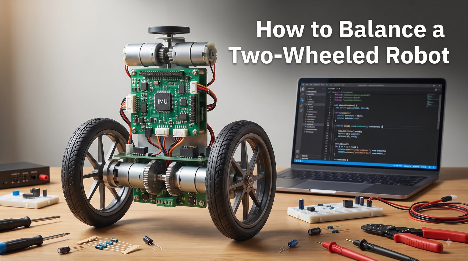
Building a robot that stands on two wheels is one of the most rewarding projects in robotics. It combines physics, electronics, programming, and mechanical design into a single challenge that teaches you how real control systems work. I have spent years building and tuning self-balancing robots, and in this guide I will walk you through everything you need to know about how to balance a two-wheeled robot from the ground up.
Whether you are a hobbyist working with Arduino or an engineering student exploring control theory, the principles stay the same. You will learn the underlying physics, component selection, wiring, programming, PID tuning, and troubleshooting in a practical, step-by-step format. By the end, you will understand exactly what makes a two-wheeled robot stay upright and how to fix it when it does not.
This guide goes deeper than most tutorials you will find online. I cover sensor fusion techniques, advanced PID tuning workflows, and real-world troubleshooting that most resources skip entirely. If you have ever watched your robot tip over and wondered why, this is the guide for you.
Table of Contents
Understanding the Physics: The Inverted Pendulum Model
A two-wheeled balancing robot is essentially an inverted pendulum on wheels. Think of balancing a broomstick on your hand. When the stick tips forward, you move your hand forward to catch it. The robot does the same thing, but with motors and wheels instead of a hand.
The key difference is speed. Your hand responds in a fraction of a second, but the robot’s control loop must read sensor data, process the algorithm, and command the motors hundreds of times per second. This closed-loop feedback system is what keeps the robot upright.
Three physical factors dominate balancing performance. The center of gravity must sit as high as possible above the wheels for the pendulum effect to work in your favor. The total mass determines how much torque the motors need. And the wheelbase width affects lateral stability, though most two-wheeled designs keep the wheels on a single axis.
Here is something I learned the hard way. If your center of gravity is too low, the robot actually becomes harder to balance, not easier. This sounds counterintuitive, but a low center of gravity reduces the natural pendulum period, meaning the control loop has less time to react before the robot falls. Aim for a tall, top-heavy design where the battery and electronics sit above the motor axle.
Essential Components for a Two-Wheeled Balancing Robot
Every balancing robot needs five core components. I will break down each one with specific recommendations based on builds I have tested personally.
Microcontroller
The brain of your robot processes sensor data and drives the control loop. An Arduino Uno works well for beginners and has plenty of community code available. If you need more processing power for sensor fusion or wireless control, an ESP32 or Raspberry Pi Pico offers faster clock speeds and more memory. I recommend starting with Arduino because the vast majority of self-balancing robot tutorials are built around it.
IMU Sensor (Gyroscope and Accelerometer)
The MPU6050 is the most popular choice for balancing robots, combining a three-axis gyroscope and three-axis accelerometer in a single chip. It is cheap, widely supported, and accurate enough for most projects. For higher precision, the BNO055 includes built-in sensor fusion and outputs calibrated orientation data directly, saving you processing work on the microcontroller.
Motors and Encoders
DC motors with built-in encoders are ideal because they provide speed and position feedback. Look for motors with high torque at low RPM, since balancing requires frequent direction changes rather than top speed. NEMA 17 stepper motors are another option that offers precise position control, but they draw more current and add complexity.
Motor Driver
An H-bridge motor driver like the L298N or TB6612FNG lets your microcontroller control motor direction and speed via PWM signals. The TB6612FNG is my preferred choice because it is more efficient and runs cooler than the L298N, which matters when your motors are constantly reversing direction.
Battery and Chassis
Balancing robots draw continuous current, so battery selection matters more than you might expect. A LiPo battery with sufficient discharge rating keeps voltage stable under load, which prevents sensor glitches and motor stuttering. For detailed guidance on this, check out our guide on battery selection for robotics projects. The chassis should be rigid, lightweight, and designed to hold components above the wheel axle for optimal center of gravity.
How to Balance a Two-Wheeled Robot: Control Algorithms Explained
The control algorithm is the heart of your balancing robot. It reads sensor data, calculates how far the robot is tilting, and commands the motors to correct. Three approaches dominate the field, and I will explain when to use each one.
PID Controller
The PID (Proportional-Integral-Derivative) controller is the most common algorithm for self-balancing robots, and for good reason. It is simple to implement, well documented, and effective for most builds. The proportional term responds to the current tilt angle. The integral term accounts for accumulated error over time. The derivative term reacts to the rate of change in the tilt.
Here is how each term contributes to balancing. The proportional term provides the main corrective force, pushing the robot back toward vertical. The derivative term dampens the response, preventing overshoot and oscillation. The integral term eliminates steady-state error, keeping the robot from slowly drifting in one direction.
LQR Controller
The Linear Quadratic Regulator is a more advanced control method that optimizes performance using a mathematical model of your robot’s dynamics. It considers the full state of the system, including angle, angular velocity, position, and velocity. LQR produces smoother, more stable balancing than PID, but it requires accurate system modeling and linear algebra that goes beyond beginner-level programming.
I recommend LQR for builders who already have a working PID robot and want to push performance further. It is especially useful for larger or heavier robots where PID struggles with stability.
Sensor Fusion: Complementary and Kalman Filters
No single sensor gives you a perfect tilt reading. Gyroscopes respond fast but drift over time. Accelerometers are accurate long-term but noisy and affected by acceleration from motor movement. Sensor fusion combines both to get the best of each.
The complementary filter is the simplest fusion method. It blends the gyroscope rate with the accelerometer angle using a weighted average, typically trusting the gyroscope for short-term changes and the accelerometer for long-term correction. This approach takes only a few lines of code and works surprisingly well for most balancing robots.
The Kalman filter is more sophisticated. It uses a statistical model to predict and correct sensor readings, accounting for measurement noise and uncertainty. Kalman filtering produces the smoothest tilt estimates but requires more processing power and mathematical understanding. For a first build, start with the complementary filter and upgrade to Kalman once your robot is balancing reliably.
Step-by-Step: Building and Wiring Your Balancing Robot
Now let me walk you through the physical build process. I will assume you have all the components from the previous section ready to go.
Step 1: Assemble the chassis. Mount the two motors symmetrically on a rigid base. Attach wheels with good traction, since slipping wheels destroy your encoder feedback. Position the battery and electronics above the motor axle to keep the center of gravity high.
Step 2: Mount the IMU sensor. Place the MPU6050 or BNO055 near the top of the robot, as close to the center axis as possible. Secure it firmly with no vibration-absorbing foam between the sensor and the frame, since you want the sensor to feel exactly what the frame feels. Loose mounting introduces noise that makes balancing impossible.
Step 3: Wire the motor driver. Connect the motor driver between your microcontroller and the motors. Wire the encoder outputs to the microcontroller’s interrupt-capable pins for accurate speed reading. For safe wiring practices, our safe robot power system wiring guide covers grounding, fusing, and wire gauge selection in detail.
Step 4: Connect the IMU. The MPU6050 communicates over I2C, so connect SDA and SCL lines to your microcontroller’s I2C pins. Add pull-up resistors if your breakout board does not include them. Double-check the I2C address, which is typically 0x68 for the MPU6050.
Step 5: Power distribution. Use a separate voltage regulator for the microcontroller and sensors to isolate them from motor noise. Motors create voltage spikes that can reset your microcontroller mid-balance, causing the robot to crash. A dedicated logic power supply prevents this entirely.
Step 6: Test before coding. Before writing any balance code, verify that each component works independently. Confirm the motors spin in both directions, the encoders report counts, and the IMU produces reasonable angle readings. I cannot tell you how many hours I have wasted debugging balance code when the real problem was a reversed motor wire.
Programming Implementation: Writing the Balance Code
The control loop is where everything comes together. Your code must read sensor data, compute the tilt angle, run the control algorithm, and drive the motors, all within a tight timing window.
Read the sensors. Start by reading raw gyroscope and accelerometer data from the IMU. Convert gyroscope rates to angles by integrating over time. Use the accelerometer to calculate the tilt angle based on gravity. Apply your chosen sensor fusion method to combine these into a single, reliable angle estimate.
Compute the error. The error is the difference between the current tilt angle and the target angle, which is typically zero (perfectly vertical). This error feeds directly into your PID controller.
Run the PID calculation. Multiply the error by the proportional gain. Integrate the error and multiply by the integral gain. Differentiate the error and multiply by the derivative gain. Sum all three terms to produce the motor command signal.
Drive the motors. Convert the PID output to a PWM signal and send it to the motor driver. If the output is positive, drive the motors forward. If negative, reverse. The magnitude determines speed.
Control the loop timing. Your control loop must run at a consistent rate, typically between 100 and 400 times per second. Use a timer interrupt or a fixed delay to maintain this rate. Inconsistent timing causes the derivative and integral terms to behave unpredictably, which destabilizes the robot.
Here is a critical tip from my own experience. Add encoder feedback to the control loop so the robot can also hold its position. Without position control, a balancing robot will slowly drift across the floor even while staying upright. Adding a position term to the PID keeps the robot in place.
PID Tuning: Getting Your Robot to Stay Upright
PID tuning is the step where most builders get stuck. Forum posts are full of people asking why their robot oscillates or falls despite hours of tweaking. Let me share the workflow that consistently works for me and the builders I have helped.
Start with all gains at zero. Set Kp, Ki, and Kd to zero. The robot will fall immediately, which is expected. You are establishing a known starting point.
Increase Kp until the robot almost balances. Slowly raise the proportional gain. At some point, the robot will start fighting to stay upright but will oscillate back and forth before falling. Note this value. Your final Kp will be roughly 60 percent of this oscillation threshold.
Add Kd to dampen oscillation. Increase the derivative gain gradually. The oscillations should decrease and the robot should hold its balance for longer periods. Too much Kd makes the robot jittery and noisy as it reacts to sensor noise. Find the sweet spot where oscillation stops but the response remains smooth.
Add Ki to correct drift. If the robot balances but slowly drifts in one direction, introduce a small integral gain. Start very low, because too much Ki causes slow oscillation that builds over time and eventually topples the robot.
Test on different surfaces. A robot tuned on carpet may behave differently on tile or concrete. Test your final parameters on multiple surfaces and adjust for the environment where the robot will actually operate.
Be patient during this process. Most builders go through dozens of tuning iterations before achieving stable balance. The community experience on forums like Reddit’s r/robotics confirms that PID tuning is universally the most time-consuming part of building a self-balancing robot. Take breaks between tuning sessions, because fresh eyes often spot what you missed.
Troubleshooting Common Balancing Robot Problems
Even with careful building and tuning, things go wrong. Here are the most common problems and how I fix them.
The robot falls immediately. Check motor direction first. If the motors drive the wrong way, the robot accelerates into the fall instead of correcting it. Swap the motor wires or reverse the sign in your code. Also verify that your angle calculation has the correct sign convention.
The robot oscillates and then falls. This usually means your proportional gain is too high or your derivative gain is too low. Reduce Kp and increase Kd. Check your loop timing as well, since a slow or inconsistent loop rate causes similar symptoms.
The robot balances but drifts sideways or in circles. Uneven motor power is the likely culprit. Add a small offset to balance the motors, or use encoder feedback to ensure both wheels rotate at the same speed. Check for mechanical issues like a binding wheel or loose motor mount.
Motors overheat during balancing. Continuous rapid direction changes draw high current. Make sure your motor driver is rated for the stall current of your motors. Consider using more efficient motors or a beefier driver like the TB6612FNG. Adding a small fan to the driver heatsink also helps significantly.
Battery drains very fast. Balancing robots draw continuous current, often 1 to 3 amps even when standing still. Use a LiPo battery with a capacity of at least 1500mAh and a discharge rating of 20C or higher. Our robot battery guide covers discharge ratings and capacity calculations for high-drain applications.
Sensor readings are noisy or jump around. Loose sensor mounting, long unshielded wires, and motor electrical noise all contribute to sensor issues. Keep IMU wires short. Add decoupling capacitors near the sensor. Make sure the sensor is rigidly mounted to the frame with no foam padding.
The robot worked on the bench but fails on the floor. This is incredibly common. On a bench, the wheels cannot move, so the robot behaves differently. Always test on the actual surface where the robot will operate. Bench testing is useful for verifying wiring and code, but it cannot replace real-world testing.
FAQs
How does a two wheeled robot balance?
A two-wheeled robot balances by using sensors (gyroscope and accelerometer) to detect its tilt angle, then driving the wheels in the direction of the fall to correct it. A control algorithm like PID runs hundreds of times per second to make continuous micro-adjustments, keeping the robot upright like balancing an inverted pendulum.
What is the best sensor for a balancing robot?
The MPU6050 is the most popular IMU sensor for balancing robots because it combines a gyroscope and accelerometer in one chip, is inexpensive, and has extensive community support. For higher precision, the BNO055 includes built-in sensor fusion and outputs calibrated orientation data directly.
How do I tune PID for a self balancing robot?
Start with all gains at zero. Increase Kp until the robot almost balances but oscillates. Add Kd to dampen the oscillation. Finally, add a small Ki to correct slow drift. Test on multiple surfaces and adjust. Expect many iterations before achieving stable balance.
Why does my self balancing robot keep falling over?
The most common causes are reversed motor direction, incorrect sign in the angle calculation, Kp set too high, inconsistent control loop timing, or a loose IMU sensor mount. Check motor direction first, then verify loop timing and sensor mounting before adjusting PID gains.
What components do I need for a balancing robot?
You need a microcontroller (Arduino, ESP32, or Raspberry Pi Pico), an IMU sensor (MPU6050 or BNO055), two DC motors with encoders, a motor driver (TB6612FNG or L298N), a LiPo battery, and a rigid chassis that holds components above the wheel axle.
Arduino or Raspberry Pi for a self balancing robot?
Arduino is better for beginners because most balancing robot tutorials and libraries are built for it, and it handles real-time control loops well. Raspberry Pi works if you need advanced features like computer vision or complex processing, but it runs a full operating system that can introduce timing jitter in the control loop.
Conclusion
Learning how to balance a two-wheeled robot takes patience, but the payoff is one of the most satisfying projects in all of robotics. You now have the complete picture, from the inverted pendulum physics and component selection through sensor fusion, control algorithms, wiring, programming, and PID tuning.
Start simple. Build with an Arduino and MPU6050, use a complementary filter, and get comfortable with PID tuning before attempting LQR or Kalman filtering. Every builder goes through iterations, so do not get discouraged when your robot falls over the first hundred times. That is part of the process.
Once your robot balances reliably, you can add advanced features like remote control, obstacle avoidance, or autonomous navigation. The control foundation you build here applies to every robotics project that involves stability and feedback control. Keep experimenting, document what works, and share your results with the community.