
When I first watched a six-axis arm place a microchip onto a circuit board without touching the surrounding components, I had to ask the same question most engineers eventually ask: how do robotic arms achieve precision at that level? The answer is not one clever trick. It is a stack of mechanical, electronic, and software systems that work together, each correcting the weaknesses of the others.
This guide walks through exactly how robotic arms achieve precision, from the motors that move them to the encoders that measure every fraction of a degree, to the control loops that close the gap between where the arm is and where it needs to be. Whether you are a student, an automation engineer, or a hobby builder trying to get smoother motion from your project, the principles below explain what actually drives robotic arm precision.
By the end, you will understand the four pillars of precision (actuators, sensors, controllers, and mechanics), why industrial arms hit 0.02 mm repeatability while hobby arms stall at 1 to 3 mm, and what you can realistically do to push precision higher on a budget.
Table of Contents
What Precision Actually Means in Robotics
Precision in robotics is the ability of a robotic arm to return to the same position, over and over, with minimal variation. Engineers call this repeatability, and it is the number most manufacturers brag about on a spec sheet. A robot rated at ±0.02 mm repeatability will land in a window 40 micrometers wide around its target, every cycle, thousands of times a day.
Accuracy is something different. Accuracy measures how close the arm gets to the position you actually asked for, not just how consistently it returns to a position. A robot can be highly repeatable but slightly inaccurate if a calibration offset exists, just as a baseball pitcher can throw the exact same pitch 100 times in a row but always miss the strike zone by a few inches.
This distinction matters because precision and accuracy are achieved by different mechanisms. Repeatability comes down to mechanical rigidity, encoder resolution, and closed-loop control. Accuracy comes down to calibration, kinematic models, and compensation for things like link deflection, thermal expansion, and backlash.
Industrial arms like those from Fanuc, KUKA, and ABB typically quote repeatability numbers between 0.02 mm and 0.1 mm. Desktop and hobby arms usually land somewhere between 1 mm and 5 mm, which is fine for pick-and-place demos but disqualifies them from any serious manufacturing role. The gap exists not because hobbyists are careless, but because each layer of precision costs real money.
The Core Components That Enable Precision
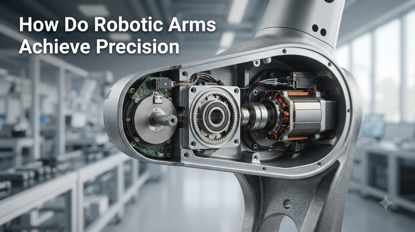
Robotic arm precision is not the product of one component. It is the product of four subsystems working in tight coordination: actuators that produce motion, sensors that measure it, controllers that decide what to do next, and mechanical structures that hold everything rigid. If any one of these is weak, the whole arm loses precision.
Actuators are the muscles. In modern industrial arms, the dominant choice is a brushless servo motor paired with a high-ratio gearbox, often a harmonic drive or planetary gearbox. Servo motors deliver smooth torque across a wide speed range and respond accurately to commands. Stepper motors show up in cheaper arms and 3D printers because they are inexpensive and hold position without feedback, but they lose steps under load and skip positions entirely if the controller pushes them too hard.
Sensors are the nervous system. The most important sensor on a precision arm is the encoder, usually mounted directly on the motor shaft or on the joint after the gearbox. Encoders report the exact angular position of the joint thousands of times per second, which lets the controller compare actual position against commanded position and correct for any error.
Controllers are the brain. A modern robot controller runs a real-time loop that reads sensor data, calculates the difference between the target pose and the current pose, decides how to move each joint, and sends new commands to the motors, all in a few milliseconds. Without a real-time controller, even the best motor and encoder combination will drift.
Mechanical structure is the skeleton. Aluminum extrusions, cast iron bases, and rigid linkages prevent the arm from flexing under load. Every millimeter of flex becomes a millimeter of error at the end effector, especially as the arm extends and the leverage grows. Industrial arms use cast and machined components precisely because flex is the enemy of precision.
For a closer look at how the gripper end of the arm contributes to overall accuracy, our article on how robotic grippers work covers the final link in that chain.
How Encoders Drive Precision Through Feedback
If you stripped a robotic arm down to the single most important precision component, it would be the encoder. Encoders are what turn a dumb motor into a measurable, controllable system. They come in two main flavors, optical and magnetic, and in two architectures, incremental and absolute, and the choice between them changes what kind of precision is possible.
Optical encoders use a glass or metal disk with fine slots, a light source, and a photodetector. As the disk spins, the slots interrupt the light beam, producing a series of pulses the controller counts. Higher line counts on the disk mean higher resolution, so a 10,000-line encoder gives 0.036 degrees of resolution per count, while a 100,000-line encoder gives 0.0036 degrees. That is the difference between a hobby arm and a surgical robot.
Magnetic encoders use a magnetized disk and Hall effect sensors to detect angular position. They are more resistant to dust, oil, and vibration than optical encoders, which is why they show up in harsh factory environments. They generally have lower resolution than high-end optical encoders, but modern designs close that gap considerably.
Incremental encoders report relative motion. They output a stream of pulses, and the controller counts them to figure out where the joint is. The catch is that the controller has no idea where the arm is at power-on, so it must run a homing routine against a limit switch before it can do anything useful. This is why industrial arms perform a calibration dance when you start them up.
Absolute encoders report absolute position. They use a unique pattern on the disk so that every angle has a unique digital code. The controller knows exactly where the joint is the moment power comes on, no homing required. Absolute encoders cost more, but for precision applications they eliminate a major source of startup error.
Encoder resolution alone does not guarantee precision. A 1 million count encoder on a sloppy mechanical assembly with backlash will still produce sloppy results. The encoder has to be paired with a rigid drivetrain, and the readings must feed a controller that actually uses them in real time.
For details on the motors that pair with these encoders, our breakdown of how servo motors work in robots goes deeper on the actuator side.
PID Controllers and the Closed Feedback Loop
Encoders measure position, but they do not control it. The control happens in the PID controller, the algorithm that turns encoder readings into motor commands. PID stands for Proportional, Integral, Derivative, and each term handles a different kind of error.
The proportional term reacts to the current error. If the arm is 0.5 mm away from the target, the proportional output commands a correction proportional to that error. Stronger error means stronger correction, which sounds great until the arm overshoots and oscillates.
The derivative term reacts to how fast the error is changing. If the arm is closing in on the target quickly, the derivative term pulls back on the motor to prevent overshoot. This is the damping that turns a nervous, jittery motion into a smooth approach.
The integral term handles accumulated error. If a small constant force, like gravity on a horizontal arm, keeps pushing the arm off target, the integral term slowly builds up a correction until the error goes away. Without it, the arm would always sit slightly below the commanded position under load.
Together, these three terms form a closed feedback loop. The controller reads the encoder, calculates the error, applies the PID formula, and updates the motor command, all in a cycle that typically runs 1,000 to 10,000 times per second. The faster the loop, the more precisely the arm can track the commanded trajectory.
Open-loop control, the kind used in basic stepper motor systems, has no feedback. The controller sends a pulse train and assumes the motor moved exactly as commanded. If the load is too high, the motor skips steps, and the arm ends up in the wrong position with no warning. Closed-loop control with PID catches those errors the instant they happen and corrects them before they grow.
This is why hobby builders who swap stepper motors for servo motors with PID tuning immediately see smoother motion and better accuracy. The closed loop is what makes the difference. It is the same principle used in cruise control, drone flight stabilization, and industrial process control, applied to the joints of a robot arm.
Mechanical Design: Backlash, Gearing, and Structure
You can have the best encoders and the tightest PID loops in the world, and your arm will still be sloppy if the mechanics are loose. Mechanical precision comes down to three factors: backlash, gear quality, and structural rigidity.
Backlash is the small amount of play in a gear train. When you reverse direction, the driven gear has to travel through the gap between teeth before it re-engages. In a robot joint, backlash shows up as a dead zone where the motor moves but the link does not. Cheap arms with plastic gears can have 1 to 2 degrees of backlash at each joint, and with six joints in series, that adds up fast.
Harmonic drives eliminate most of this problem. A harmonic drive uses a flexible spline that deforms as it engages, providing near-zero backlash and very high gear ratios in a compact package. They are expensive, which is why they show up in industrial arms and not in $200 hobby kits, but they are one of the single biggest contributors to industrial-grade precision.
Planetary gearboxes are the middle ground. They offer lower backlash than simple spur gears and handle higher torque than harmonic drives in some configurations. You will find them in mid-range robotic arms and CNC machines where precision matters but the budget cannot stretch to harmonic drives on every joint.
Structural rigidity is the silent contributor. A robotic arm is essentially a cantilever, and like any cantilever, it deflects under load. The longer the arm and the heavier the payload, the more it bends. Industrial arms use cast iron and machined steel links to keep deflection under 0.05 mm at full reach. Hobby arms built from aluminum extrusion and 3D printed parts can deflect 1 mm or more, which is fine for moving ping pong balls but disqualifies them for any real work.
Bearings matter too. Cheap bushings develop slop as they wear, and that slop becomes position error at the end effector. Precision arms use preloaded angular contact or crossed roller bearings at every joint to keep the motion tight over years of service.
To understand the gearing side in more depth, our guide on how planetary gearboxes work in robot joints breaks down the mechanics that make all of this possible.
Calibration and Error Correction Methods
Even the best-built arm has small errors that build up over its workspace. Calibration is the process of measuring those errors and teaching the controller to compensate for them. There are several levels of calibration, ranging from simple to highly sophisticated.
The most basic calibration is homing. Every time the arm powers on, it moves each joint until it hits a known reference switch, then resets its encoder count to zero. This establishes a known starting position but does not account for errors elsewhere in the workspace.
Kinematic calibration goes further. It uses measured positions across the workspace, often captured with a motion capture system or a laser tracker, to refine the arm’s mathematical model. The controller learns the actual link lengths, joint offsets, and deflection values, then applies corrections whenever it calculates a target pose. A well-calibrated industrial arm can have its accuracy improved by a factor of 10 or more.
Sensor fusion combines multiple sensors to overcome the weaknesses of any single one. A robot might combine joint encoders, a wrist-mounted camera, and force-torque sensors to know where it is, what it is touching, and how hard it is pushing. The controller cross-checks these sources to detect and correct errors in real time.
Thermal compensation handles the slow drift caused by heat. Motors and gearboxes warm up during use, which changes their dimensions slightly. High-end controllers track temperature sensors on each joint and apply corrections as the arm heats up, keeping precision consistent from a cold start to a fully warmed up production run.
Why Hobby and Industrial Arms Differ So Much
In forums like r/robotics, the same conversation comes up over and over. Hobbyists build a six-axis arm with servos and aluminum brackets, expect industrial precision, and are disappointed to find 2 mm of slop. The reason is not bad design. It is physics, materials, and the cost of precision components.
Industrial arms use harmonic drives that cost more than an entire hobby arm. They use absolute encoders with 20-bit resolution. They use servo motors with torque margins five to ten times what the load actually requires. They use cast metal structures machined to tight tolerances. Every one of those choices multiplies the price tag.
Hobby arms typically use standard hobby servos with plastic gears, no closed-loop position control in the firmware, and printed or extruded frames. The user community has found that even the best open source arms cannot get below about 1 mm of accuracy without major upgrades. Industrial arms hit 0.02 mm not because their designers are smarter, but because they are spending 50 to 200 times more on components.
The good news for hobbyists is that targeted upgrades help. Replacing plastic-geared servos with metal-geared digital servos, adding external encoders, and switching to a closed-loop controller like ODrive or VESC can push a hobby arm into the 0.2 to 0.5 mm range. That is still not industrial precision, but it is enough for serious hobby projects, light pick-and-place, and a lot of educational use.
For anyone choosing a precision level, the rule of thumb is to match the arm to the task. A 1 mm precision arm can place a coffee cup. A 0.1 mm precision arm can place a microchip. A 0.02 mm precision arm can place a fiber optic strand. Choose based on the smallest feature you need to handle, then budget for the components that hit that target.
Frequently Asked Questions
What is precision in robotics?
Precision in robotics is the ability of a robotic arm to return to the same position repeatedly with minimal variation. Engineers usually call this repeatability, and it is the number most often quoted on a robot’s spec sheet. A robot rated at 0.02 mm precision will land within a 40 micrometer window around its target on every cycle.
How do robotic arms work?
Robotic arms work by combining actuators (usually servo motors), sensors (encoders and sometimes force or vision sensors), a real-time controller, and a rigid mechanical structure. The controller reads sensor data, compares the actual position of each joint to the commanded position, calculates corrections using algorithms like PID, and sends updated commands to the motors thousands of times per second.
What are the limitations of robotic arms?
Robotic arms are limited by mechanical backlash, structural flex under load, encoder resolution, and the accuracy of their calibration. Hobby and desktop arms typically achieve only 1 to 3 mm of accuracy. Industrial arms reach 0.02 to 0.1 mm but cost far more. Environmental factors like temperature and vibration also affect precision.
How do encoders work in robots?
Encoders in robots measure the angular position of each joint using either optical or magnetic sensing. Optical encoders count light pulses through a slotted disk, while magnetic encoders use Hall effect sensors on a magnetized disk. Absolute encoders report the exact angle on power-up, while incremental encoders count pulses from a reference point.
What is repeatability in robotics?
Repeatability in robotics is the measure of how consistently a robot can return to a position it has already visited. It is expressed as a tolerance, such as plus or minus 0.02 mm, and it is the most common precision metric used by manufacturers. High repeatability is what allows industrial arms to perform the same assembly task millions of times without drift.
How accurate are industrial robots?
Industrial robots are typically accurate to within 0.02 to 0.1 mm, depending on the model, payload, and reach. After kinematic calibration, some high-end arms reach accuracies below 0.01 mm. This level of precision enables tasks like microchip placement, laser cutting, and精密 assembly in electronics manufacturing.
Final Thoughts on Robotic Arm Precision
So how do robotic arms achieve precision in the real world? It comes from four systems working in lockstep. Servo motors produce smooth, controllable torque. Encoders measure every fraction of a degree of motion. PID controllers close the loop between commanded and actual position thousands of times per second. And rigid mechanical structures, harmonic drives, and preloaded bearings make sure that motion translates faithfully from motor to end effector.
Take any one of these systems away and precision collapses. Strip the encoders and the controller has no idea where the arm is. Strip the PID and the arm oscillates or overshoots. Strip the harmonic drives and backlash creeps into every joint. Strip the rigid structure and the arm flexes under load like a fishing rod.
For builders, the lesson is that precision comes from systems, not single components. Upgrading your hobby arm’s motors without upgrading the encoders and controller will not get you industrial performance. Upgrading your controllers without addressing backlash in the gear train will leave the same dead zone at every joint reversal.
Looking forward, the next wave of precision improvement is coming from software. Machine learning models are starting to predict and compensate for thermal drift, payload-induced flex, and even individual manufacturing variations between robots. Combined with the same encoders, motors, and rigid mechanics described above, these software layers are pushing precision into the sub-micrometer range, opening up applications like microsurgery, semiconductor inspection, and fiber optic alignment that would have been impossible with classic control alone.
Whether you are designing your first arm, specifying one for a production line, or just curious about how a machine can place a part within the width of a human hair, the precision story is the same: measure, compare, correct, repeat, and do it all in milliseconds.