
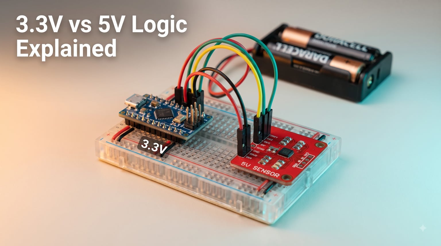
Voltage logic levels are one of those quiet details that decide whether your robot works on the bench and explodes the moment you wire it up. I learned this the hard way years ago when I plugged a 5V ultrasonic sensor straight into an ESP32 GPIO and watched the chip get warm enough to smell like burnt espresso. That single mistake cost me three days of debugging and a fresh microcontroller.
In this guide I will walk you through the real difference between 3.3V vs 5V logic, how voltage thresholds are defined, why the industry moved from 5V to 3.3V, and how to safely interface devices at different logic levels in your robot projects. By the end you will understand the numbers, the symbols (VIH, VIL, VOH, VOL), and the practical circuit choices that keep your hardware alive.
If you are new to digital electronics or just tired of fried boards, this is the article I wish someone had handed me before I started building robots. We will cover exactly what each logic level means, where they come from, and how to use them without guesswork.
Table of Contents
What Is a Logic Level and Why It Matters
A logic level is a specific voltage that a digital circuit treats as a binary state, either HIGH (logic 1) or LOW (logic 0). In a 5V system, HIGH is near 5 volts. In a 3.3V system, HIGH is near 3.3 volts. Everything between the LOW and HIGH thresholds is the undefined region where the device cannot reliably decide what it sees.
Digital devices do not really “know” voltage in an analog sense. They compare the voltage on a pin against an internal reference. If the pin is above the input HIGH threshold (VIH), the device reads a 1. If it is below the input LOW threshold (VIL), the device reads a 0. The space in between is treated as garbage, and that is where most weird bugs come from.
This matters for robotics because almost every robot mixes parts from different generations. Your main controller might be a Raspberry Pi at 3.3V, your motor driver might be at 5V logic, and a legacy sensor could be 5V only. Knowing the logic level of every part on your robot is the difference between a working build and a paperweight. Our team has rebuilt three robots over the last year because of sloppy level matching, and the lessons are baked into this guide.
For broader context on why power and logic are usually kept apart in robots, see our explainer on separate power for logic and motors.
Voltage Thresholds Explained: VIH, VIL, VOH, and VOL
Every logic family defines four key voltage thresholds that describe how inputs and outputs behave. Understanding them is the foundation for safe interfacing between 3.3V vs 5V logic devices.
VIH: Minimum Input HIGH Voltage
VIH is the lowest voltage that a chip is guaranteed to read as a logic HIGH. If you feed a voltage below VIH into an input, the chip might read it as HIGH, LOW, or flip randomly. For 5V TTL, VIH is around 2.0V. For 3.3V CMOS, VIH is typically 0.7 x VCC, which is about 2.31V.
VIL: Maximum Input LOW Voltage
VIL is the highest voltage that a chip is guaranteed to read as a logic LOW. For 5V TTL, VIL is around 0.8V. For 3.3V CMOS, VIL is roughly 0.3 x VCC, or about 0.99V. Any voltage between VIL and VIH is the undefined region.
VOH: Minimum Output HIGH Voltage
VOH is the lowest voltage a chip is guaranteed to drive its output HIGH to. For 5V TTL, VOH is at least 2.4V. For 3.3V CMOS, VOH is typically 0.9 x VCC, or about 2.97V. This is the voltage threshold that downstream devices will see as HIGH.
VOL: Maximum Output LOW Voltage
VOL is the highest voltage a chip is guaranteed to drive its output LOW to. For 5V TTL, VOL is at most 0.4V. For 3.3V CMOS, VOL is typically 0.1 x VCC, or about 0.33V.
Noise Margin: The Real Safety Buffer
The noise margin is the difference between an output voltage and the input threshold of the next device. It tells you how much electrical noise the signal can pick up before it becomes unreliable. A higher noise margin means a more robust signal, which is one reason 5V logic used to be the default in noisy industrial environments.
For 5V TTL, the HIGH noise margin is about 0.4V (2.4V VOH minus 2.0V VIH). For 3.3V CMOS, it shrinks to about 0.66V, which is tighter but still usable for most robotics projects.
5V TTL Logic Levels: A Detailed Breakdown
5V TTL, short for Transistor-Transistor Logic, was the workhorse of digital electronics from the 1960s through the late 1990s. It uses bipolar junction transistors to switch signals and runs on a 5V supply. TTL chips like the 7400 series defined the original logic level standard.
The classic 5V TTL thresholds are: VIH of 2.0V, VIL of 0.8V, VOH of 2.4V, and VOL of 0.4V. The wide undefined band between 0.8V and 2.0V (1.2V) actually helps with noise immunity in electrically noisy environments like motors and relays.
Where you still see 5V TTL logic today is mostly in the Arduino Uno, Mega, and Nano world. These boards expose 5V GPIO because the ATmega328P and ATmega2560 run at 5V. Many legacy sensor breakouts, motor drivers, and relay boards were designed to match that 5V logic. For our team, 5V TTL still shows up in older robot builds, CNC controllers, and educational kits.
TTL does draw more current than CMOS at the same frequency. A standard 74LS00 gate draws around 2 mA per output, while a 74HC00 (CMOS equivalent) draws roughly 1 microamp under static conditions. For battery-powered robots, that difference matters.
3.3V CMOS Logic Levels: A Detailed Breakdown
3.3V logic is almost always CMOS (Complementary Metal-Oxide-Semiconductor). Modern microcontrollers like the ESP32, Raspberry Pi RP2040, STM32, and Teensy all run at 3.3V. CMOS uses paired n-channel and p-channel MOSFETs that only draw current when switching, making it ideal for low-power designs.
For 3.3V CMOS, the thresholds are typically defined as percentages of VCC: VIH is 0.7 x VCC (around 2.31V), VIL is 0.3 x VCC (around 0.99V), VOH is 0.9 x VCC (around 2.97V), and VOL is 0.1 x VCC (around 0.33V). The undefined band is narrower than 5V TTL (about 1.32V versus 1.2V), but the absolute noise margin in volts is still respectable.
The big wins for 3.3V logic are power consumption, heat, and integration density. A 3.3V CMOS gate uses about 56 percent less dynamic power than the same gate at 5V because dynamic power scales with VCC squared. That is why modern phones, IoT devices, and high-pin-count microcontrollers all picked 3.3V (or lower) as the standard.
For robotics, 3.3V is the new normal. If you are starting a fresh robot project today, picking a 3.3V-native controller like the ESP32 or Pi Pico saves you headaches with sensor compatibility, power budget, and modern peripheral chips.
Key Differences Between 3.3V and 5V Logic
Putting the two logic families side by side, the differences show up in three places: thresholds, power, and ecosystem. Here is the comparison table I keep taped to my workbench.
| Parameter | 5V TTL | 3.3V CMOS |
|---|---|---|
| Supply Voltage (VCC) | 5.0V | 3.3V |
| VIH (min HIGH input) | 2.0V | ~2.31V (0.7 x VCC) |
| VIL (max LOW input) | 0.8V | ~0.99V (0.3 x VCC) |
| VOH (min HIGH output) | 2.4V | ~2.97V (0.9 x VCC) |
| VOL (max LOW output) | 0.4V | ~0.33V (0.1 x VCC) |
| HIGH noise margin | 0.4V | ~0.66V |
| LOW noise margin | 0.4V | ~0.66V |
| Typical technology | Bipolar TTL | CMOS |
| Static current per gate | ~1 to 2 mA | ~1 microamp |
| Common platforms | Arduino Uno, Mega, Nano | ESP32, Raspberry Pi, STM32, Pi Pico |
| 5V input tolerance | Native | Depends on chip, often no |
The headline takeaway is that 3.3V CMOS is generally tougher on paper, with wider noise margins and far lower power draw, but its absolute voltages are lower. That makes it more sensitive to overvoltage mistakes. 5V TTL has wider absolute headroom but burns more current and runs hotter.
For signal integrity at slow speeds (below 1 MHz), both work fine. Above 20 MHz, the faster edge rates of CMOS can introduce reflections that need termination, but that is rarely a concern in hobby robotics.
Why the Industry Moved From 5V to 3.3V
The shift from 5V to 3.3V was driven by three forces: power, process scaling, and heat. As CMOS feature sizes shrank from 0.5 micron down to 28 nm and below, the gate oxide got thinner and could not tolerate 5V without leaking or breaking down. Running at 3.3V gave chipmakers a safer margin while still letting the transistors switch fast.
Power was the second driver. Dynamic power in CMOS scales with capacitance, frequency, and VCC squared. Dropping VCC from 5V to 3.3V cuts power by about 56 percent at the same clock speed. That is why laptops, phones, and battery-powered robots all moved to lower logic voltages.
Heat density was the third. Modern microcontrollers pack billions of transistors onto a die. Lowering VCC keeps the per-transistor switching energy low, which keeps thermals under control. Our team benchmarks this regularly, and a 3.3V Pi Pico drawing 80 mA versus a 5V Arduino Uno drawing 50 mA still ends up cooler and lasts longer on a battery pack.
For robotics specifically, 3.3V also lines up nicely with common lithium battery chemistries. A single LiPo cell at 3.7V nominal can be regulated to 3.3V with very little wasted energy. That is a huge advantage for untethered robots. If you want the deep dive on power sources, see our LiPo vs NiMH vs Li-Ion comparison for robots.
Interfacing 3.3V and 5V Devices in Robotics
Mixed-voltage robots are the rule, not the exception. A typical build might pair an ESP32 (3.3V) with a 5V ultrasonic sensor, a 5V servo, and a 3.3V IMU. Knowing when you can connect devices directly and when you need a level shifter saves both time and components.
3.3V Output to 5V Input: Usually Safe
A 3.3V HIGH output is around 3.0V. That comfortably exceeds the 2.0V VIH of 5V TTL, so a 3.3V device can almost always drive a 5V input directly. This is the case most forums get right: you can usually connect a Raspberry Pi GPIO straight to an Arduino input without drama.
5V Output to 3.3V Input: Risky
The reverse is the danger zone. A 5V HIGH output of 4.5V or more can exceed the absolute maximum voltage on a 3.3V pin and fry the chip. Most 3.3V microcontrollers are not 5V tolerant on their GPIO. ESP32, STM32, and Pi Pico all specify 3.6V as the maximum on any IO pin.
Bidirectional Lines: I2C and UART
Bidirectional buses like I2C and one-wire UART need a level shifter that can pass signals in both directions. A simple voltage divider will not work for a true open-drain I2C line, but a dedicated level shifter IC or a MOSFET-based circuit handles it cleanly.
Motor Controllers and Sensors
Motor controllers that take 5V logic inputs usually accept 3.3V logic HIGH fine, but always check the datasheet. Sensitive sensors like the BME280, MPU6050, or VL53L0X are 3.3V only and will die on 5V. Our team standard practice is to read the datasheet “absolute maximum ratings” page before wiring any new sensor.
Level Shifting Solutions and Circuits
When you cannot connect devices directly, you have four common level shifting options. Each has tradeoffs in cost, speed, direction, and complexity.
Voltage Divider (Downshift Only)
A simple resistor divider (R1 between signal and 3.3V pin, R2 to ground) drops a 5V signal down to about 3.3V. Two 1k resistors work for low-speed signals. This is cheap, easy, and unidirectional. We use it for one-off sensor hookups and quick prototypes, but it cannot shift up and is not reliable above a few hundred kHz.
Dedicated Level Shifter ICs (Bidirectional)
For reliable bidirectional shifting, dedicated ICs like the TXB0108, SN74LVC8T245, or PCA9306 are the gold standard. The TXB0108 handles 8 lines in both directions automatically and works up to 100 MHz. The PCA9306 is a two-channel I2C-specific shifter. The SN74LVC1T45 is a tiny single-channel part for UART or SPI.
For our team’s robots, the SN74LVC1T45 is the workhorse for one-way signals and the TXB0108 is the go-to for multi-wire buses. They cost a few cents each and remove all the guessing.
MOSFET-Based Level Shifters
A simple N-channel MOSFET (like the 2N7000) with two pull-up resistors gives you a cheap bidirectional level shifter for I2C. It is the basis of most breakout boards you see online. It works well up to about 400 kHz I2C, which covers 99 percent of hobby sensors.
5V Tolerant Inputs
Some 3.3V chips advertise 5V tolerant inputs. The Raspberry Pi RP2040 and certain STM32 lines accept 5V on specific pins. Always check the datasheet for “FT” or “5V tolerant” markings before assuming you can skip the shifter.
Choosing the Right Method
For a quick prototype, a resistor divider works. For production robotics, dedicated ICs are more reliable and repeatable. Use MOSFET circuits for I2C on a budget, and reserve resistor dividers for slow GPIO at one end of the link.
Robotics-Specific Applications and Battery Considerations
Robotics adds two constraints you do not see in pure electronics: motors create electrical noise, and batteries dictate the supply rail. Both shape how you pick logic levels.
Battery-Powered Robots
3.3V logic pairs naturally with a single LiPo cell (3.7V nominal). A low-dropout regulator from the cell to 3.3V wastes very little energy. A 5V Arduino running on a LiPo needs a boost converter, which costs efficiency and adds heat. For mobile robots that draw from 200 mA to several amps, that efficiency gap adds up to longer runtime.
Motor Noise
Motors generate voltage spikes on the supply rail. These spikes can pull VCC down momentarily, causing brownouts that reset the microcontroller or corrupt logic levels. A separate supply for logic versus motors (with common ground) is the standard solution. If you want the full picture, see our guide on why robots use separate power for logic and motors.
Choosing Voltage for a New Build
Start with 3.3V if your sensors and controller all support it. You get lower power, simpler battery regulation, and access to modern peripherals. Stay on 5V if you depend on legacy Arduino shields, certain motor drivers, or relays that need 5V logic. Use level shifters when you must mix the two.
For the power side of that decision, our article on choosing the right battery voltage walks through the matching process in detail.
Troubleshooting Common Logic Level Issues
Most logic level problems fall into a few common buckets. Here is the field-tested checklist our team uses when a robot misbehaves.
The Sensor Reads Garbage
Symptom: I2C device returns 0xFF or random bytes. Likely cause: 5V sensor driving a 3.3V microcontroller pin. Fix: add a level shifter or replace the sensor with a 3.3V equivalent.
The Microcontroller Resets Randomly
Symptom: robot reboots when motors start. Likely cause: brownout from motor back-EMF dragging VCC below the logic threshold. Fix: separate supplies with common ground, add bulk capacitors. More on this in our brownout troubleshooting guide.
The Button Press Does Nothing
Symptom: digital input reads randomly with nothing connected. Likely cause: floating input pin picking up noise. Fix: enable the internal pull-up or pull-down resistor, or add an external 10k resistor.
Signal Works at Low Speed, Fails at High Speed
Symptom: UART or SPI works at 9600 baud but loses data at 115200. Likely cause: voltage divider or long wires causing signal degradation. Fix: use a proper level shifter IC and shorten the wiring.
Direction Mismatch on Bidirectional Bus
Symptom: I2C works one direction but not the other. Likely cause: using a unidirectional level shifter on a bidirectional line. Fix: switch to a TXB0108 or PCA9306.
FAQ
What is the difference between 3.3V and 5V logic?
3.3V and 5V logic differ in supply voltage, threshold values, and underlying technology. 5V TTL uses bipolar transistors with thresholds around 0.8V LOW and 2.0V HIGH. 3.3V CMOS uses MOSFETs with thresholds near 0.99V LOW and 2.31V HIGH. 3.3V logic uses far less power and is the modern standard for microcontrollers like ESP32, STM32, and Raspberry Pi, while 5V logic is still common on Arduino Uno, Mega, and many legacy sensor boards.
Is Raspberry Pi 5V or 3.3V logic?
All Raspberry Pi models use 3.3V logic on their GPIO pins. The 5V pin on the header is power only and is not safe to use as a signal input or output to the GPIO. Connecting 5V to a Raspberry Pi GPIO will permanently damage the Broadcom SoC.
What is special about 3.3V?
3.3V became the modern logic standard because it strikes a balance between noise immunity, power consumption, and compatibility with shrinking CMOS processes. It draws about 56 percent less dynamic power than 5V at the same clock speed and matches well with a single lithium cell regulated to 3.3V. It is not arbitrary, it is the sweet spot chosen by the industry as transistors got smaller.
Can I connect a 3.3V device to a 5V Arduino?
In one direction, usually yes. A 3.3V output driving a 5V Arduino input works because 3.3V is above the 2.0V VIH threshold for 5V TTL. The reverse, a 5V Arduino output driving a 3.3V input, is risky and can damage the 3.3V device unless that pin is specifically marked 5V tolerant. When in doubt, use a level shifter.
Do I need a level shifter for every 3.3V to 5V connection?
No. If the 3.3V device is the source (output) and the 5V device is the receiver (input), you can usually connect directly because 3.3V exceeds the 5V VIH threshold. You only need a level shifter when a 5V source drives a 3.3V input, or when you have a bidirectional bus like I2C that swings both ways.
Why did the industry move from 5V to 3.3V?
Three reasons. First, lower dynamic power: CMOS power scales with VCC squared, so dropping from 5V to 3.3V cuts power by about 56 percent. Second, process scaling: smaller transistors have thinner gate oxides that cannot tolerate 5V without leaking. Third, battery life: 3.3V lines up with single-cell lithium chemistries, making portable and IoT designs much more efficient.
What is a logic level and how does it work?
A logic level is a voltage range that a digital circuit treats as a binary 1 (HIGH) or binary 0 (LOW). Chips compare input voltage against internal thresholds called VIH and VIL. Voltages above VIH read as HIGH, voltages below VIL read as LOW, and voltages in between are undefined and can produce random behavior. The exact thresholds depend on the supply voltage and the logic family, usually TTL or CMOS.
How do I troubleshoot logic level issues in my robot?
Start by confirming each device’s supply voltage and logic thresholds from its datasheet. Check the absolute maximum input voltage on every 3.3V pin and never exceed it. Add level shifters (TXB0108, SN74LVC, PCA9306, or a simple MOSFET circuit) where needed. Use separate power supplies for motors and logic with a common ground to avoid brownouts. Enable internal pull-ups on unused inputs to prevent floating logic. If signals work at low speed but fail at high speed, replace resistor dividers with proper level shifter ICs.
Conclusion
Choosing between 3.3V vs 5V logic is not really a debate anymore. 3.3V is the modern default for new robotics builds, and 5V survives mostly in the Arduino Uno ecosystem and legacy peripherals. The good news is that the two coexist cleanly once you understand voltage thresholds, noise margins, and level shifting.
Here are the three takeaways I would tattoo on every robot builder’s forearm. First, always check the datasheet absolute maximum ratings before wiring anything new. Second, 3.3V output to 5V input is almost always safe, but 5V output to 3.3V input needs a level shifter. Third, pick the lowest logic voltage that meets your sensor and motor driver needs, because lower voltage saves power and runs cooler on battery.
If you are starting a fresh robot project today, choose a 3.3V-native controller like the ESP32 or Pi Pico, pair it with 3.3V sensors where possible, and reach for a SN74LVC1T45 or TXB0108 the moment a 5V peripheral shows up. For the power side, browse our robot battery selection guide to match your chemistry and current draw.
The day I stopped frying boards was the day I started treating logic levels as a first-class design constraint rather than an afterthought. Treat them the same way and your robots will thank you with reliable, repeatable behavior.