
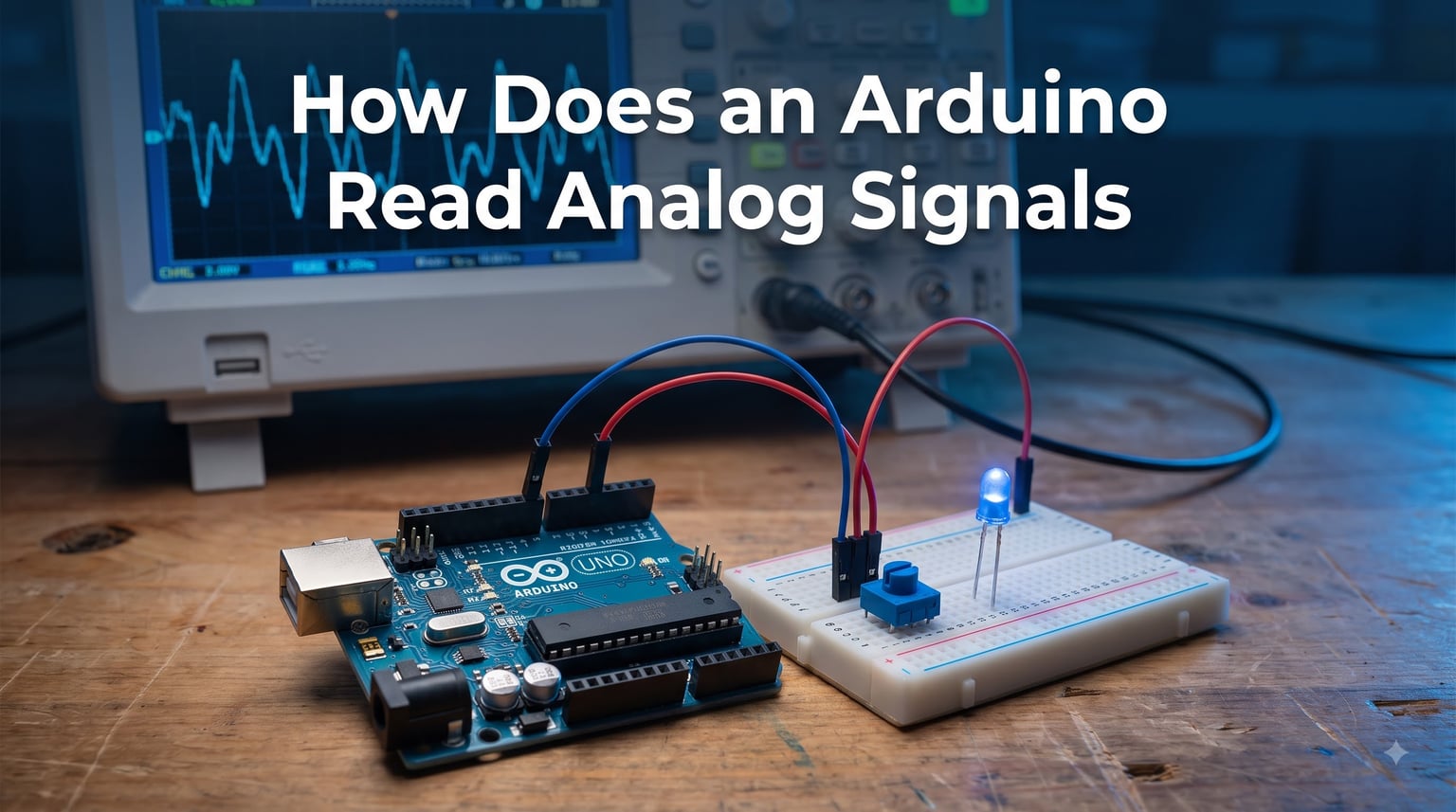
Every Arduino project that interacts with the real world depends on one fundamental capability: reading analog signals. Whether you are building a temperature monitoring station, a light-tracking solar panel, or a motor speed controller, understanding how the analog-to-digital conversion process works is the key to getting reliable data from your sensors.
The short answer is that Arduino uses a built-in Analog-to-Digital Converter (ADC) to sample the voltage on its analog pins and convert it into a digital number. On the Arduino UNO, this converter has 10-bit resolution, meaning it divides the 0 to 5V range into 1,024 discrete steps of approximately 4.88mV each. Every time you call analogRead(), the ADC kicks in and returns a value between 0 and 1023.
In this guide, I will walk you through exactly how that process works from the hardware level up to the code you write. We will cover the ADC internals, resolution, reference voltage, sampling speed, troubleshooting noisy readings, and practical code examples you can use right away. By the end, you will know precisely what happens inside the chip when that function runs.
If you are working on robot sensor applications or any project that measures physical quantities, this knowledge helps you choose the right approach and avoid common pitfalls that produce unreliable data.
Table of Contents
What Is an Analog Signal and Why Arduino Needs to Read It
An analog signal is a continuously varying voltage. Unlike a digital signal, which is either HIGH (5V) or LOW (0V), an analog signal can take on any value in between. A temperature sensor might output 1.7V at 25 degrees Celsius, 2.1V at 35 degrees, and so on in a smooth curve.
The problem is that microcontrollers like the ATmega328P on the Arduino UNO are digital devices. Their brains process ones and zeros, not continuous voltages. They cannot directly understand what 1.7V means without translating it into a number first.
That translation is the job of the Analog-to-Digital Converter. The ADC acts as a bridge between the analog world of sensors, batteries, and physical measurements and the digital world of your Arduino code. Without it, you could only read buttons and switches. With it, you can measure temperature, light intensity, sound levels, position, force, and dozens of other real-world quantities.
Common sensors that produce analog output include potentiometers, thermistors, photoresistors (LDRs), flex sensors, gas sensors, and many accelerometers. If a sensor has three pins (VCC, GND, and signal) and its datasheet mentions an output voltage range, it almost certainly needs the ADC.
How Does an Arduino Read Analog Signals: The ADC Explained
Here is the direct answer: an Arduino reads analog signals using a built-in ADC peripheral inside the microcontroller chip. This ADC uses a technique called successive approximation to convert an incoming voltage into a digital number, typically completing the conversion in about 100 microseconds on the UNO.
The successive approximation process works through binary search. Inside the ADC, there is a comparator and a digital-to-analog converter. The ADC generates a test voltage, compares it to your input signal, and adjusts the test voltage up or down. It does this for each bit of resolution, narrowing in on the closest match.
Here is the step-by-step process that happens inside the chip:
Step 1: Your code calls
analogRead(A0), which tells the microcontroller’s ADC multiplexer to connect analog pin A0 to the ADC input.Step 2: The ADC charges an internal sampling capacitor to match the voltage on the pin. This takes a brief moment and is part of why source impedance matters (more on that later).
Step 3: The successive approximation register begins its binary search. It starts with the most significant bit, sets it to 1, and checks whether the resulting test voltage is higher or lower than the input.
Step 4: For each bit, the comparator tells the logic whether to keep or clear that bit. With 10 bits, this takes 10 clock cycles of the ADC.
Step 5: The final 10-bit result is placed in the ADC data register, and
analogRead()returns it to your sketch as an integer between 0 and 1023.
This entire sequence repeats every time you call analogRead(). On the UNO, the ADC clock runs at 125kHz (the 16MHz system clock divided by a prescaler of 128), and a full 10-bit conversion takes 13 ADC clock cycles, which works out to roughly 104 microseconds.
ADC Resolution and Bit Depth: Understanding the 10-Bit Converter
Resolution determines how finely the ADC can divide the input voltage range. A 10-bit ADC, like the one on the Arduino UNO and Nano, produces 2 to the power of 10, or 1,024, possible output values. These values range from 0 to 1023.
To calculate the voltage per step, divide the reference voltage by the number of steps. With a 5V reference, that is 5.0 divided by 1024, giving 4.88mV per step. This means the ADC can distinguish changes of about 4.88mV but cannot resolve anything smaller.
For example, if your sensor outputs 2.500V, the ADC produces a reading of 512. If it outputs 2.505V, the reading is still 512 because 5mV is below one step. At 2.510V, the reading jumps to 513.
Different Arduino boards have different ADC resolutions. The Arduino UNO, Nano, and Mega all use 10-bit ADCs (0-1023). The Arduino Due has a 12-bit ADC by default (0-4095), and it can be configured for up to 12 bits through the analogReadResolution() function. The ESP32-based boards offer up to 12-bit resolution as well, giving finer granularity.
If you need even higher resolution, external ADC chips like the ADS1115 (16-bit) or the MCP3208 (12-bit) connect via I2C or SPI and give you far more precision than the built-in converter.
Reference Voltage (VREF): The Foundation of Every Reading
The reference voltage, or VREF, is the maximum voltage the ADC can measure. It sets the upper boundary of the conversion range. Any input voltage equal to or above VREF produces a reading of 1023, and any voltage at 0V produces 0.
Arduino gives you three reference voltage options through the analogReference() function:
DEFAULT: Uses the board’s supply voltage, which is 5V on the UNO, Nano, and Mega, or 3.3V on the Due and some smaller boards. This is what every sketch uses unless you change it. It is the simplest option but also the least precise when working with small signals.
INTERNAL: Uses an internal 1.1V reference on the ATmega328P (UNO, Nano) or 2.56V on the ATmega2560 (Mega). This is excellent for sensors that output low voltages because it gives you finer resolution. With the 1.1V internal reference, each step is only 1.07mV instead of 4.88mV.
EXTERNAL: Connects the ADC to an external voltage applied to the AREF pin. You would use this when you need a specific, highly stable reference voltage, such as 3.3V from a precision voltage reference IC.
One important warning: never apply a voltage to the AREF pin without first calling analogReference(EXTERNAL) in your setup. If you apply voltage to AREF while the internal reference is still selected, you can short-circuit and damage the chip. I have seen beginners destroy boards this way.
The reference voltage also appears in the voltage conversion formula, so if you change VREF, your conversion math must update too. Using analogReference(INTERNAL) with a formula that still divides by 5V will give you completely wrong readings.
The analogRead() Function: Your Gateway to Analog Data
The analogRead() function is the command you use in your Arduino sketch to read an analog pin. Its syntax is straightforward: pass the pin number as the argument, and it returns an integer.
int sensorValue = analogRead(A0);This single line reads the voltage on pin A0, runs the full ADC conversion, and stores the result in the variable sensorValue. The return value is always an integer between 0 and 1023 on a 10-bit board.
Notice I used A0 and not just 0. On the Arduino UNO and Nano, the analog pins are labeled A0 through A5 on the silkscreen. You can use either A0 or 14 (the underlying pin number), but A0 is far more readable and avoids confusion with digital pin 0. Forum users consistently recommend the A0 notation for this reason.
One thing to keep in mind is that analogRead() is a blocking function. It takes about 100 microseconds to complete, during which your code does nothing else. For most projects this is negligible, but if you are doing high-speed sampling or time-critical operations, you may need to look into interrupt-driven ADC or free-running mode.
Also note that analog pins do not need to be configured with pinMode(). The Arduino automatically handles the pin setup when you call analogRead(). Calling pinMode(A0, INPUT) is harmless but unnecessary.
Converting ADC Values to Real Voltage: The Formula
Once you have a raw ADC value, you usually want to convert it to an actual voltage. The formula is simple and comes directly from the relationship between the ADC reading, the reference voltage, and the number of steps.
voltage = sensorValue * (VREF / 1023.0);Using the default 5V reference, this becomes:
float voltage = sensorValue * (5.0 / 1023.0);So if analogRead(A0) returns 512, the voltage is 512 times 5.0 divided by 1023, which equals approximately 2.5V. A reading of 0 gives 0V, and a reading of 1023 gives 5.0V.
Some people divide by 1024 instead of 1023. Technically, 1024 is more correct because there are 1024 steps, but the difference is only 0.1% and rarely matters in practice. Arduino’s own official documentation uses 1023 in the ReadAnalogVoltage example.
If you changed the reference voltage to the internal 1.1V reference, update the formula accordingly:
float voltage = sensorValue * (1.1 / 1023.0);And if you are using an external reference, replace the number with whatever voltage you applied to AREF.
Arduino Board Comparison: Analog Capabilities Across Models
Different Arduino boards have different analog capabilities. Knowing the specifics of your board helps you plan your project correctly. Here is a comparison of the most popular models:
Arduino UNO (ATmega328P): 6 analog input pins (A0-A5), 10-bit resolution, default 5V reference, internal 1.1V reference option. This is the board most beginners use and the one this guide focuses on.
Arduino Nano (ATmega328P): 8 analog input pins (A0-A7), 10-bit resolution. The Nano uses the same chip as the UNO but exposes two additional analog pins. This makes it great for compact projects needing more sensor inputs.
Arduino Mega 2560 (ATmega2560): 16 analog input pins (A0-A15), 10-bit resolution, internal 2.56V reference option. The Mega is ideal for complex projects that need many analog sensors.
Arduino Due (ATSAM3X8E): 12 analog input pins, 12-bit resolution (0-4095), 3.3V logic level. The Due offers finer resolution and more inputs but operates at 3.3V, so it is not 5V tolerant. Be careful not to feed 5V signals into its analog pins.
Arduino Leonardo (ATmega32U4): 12 analog input pins, 10-bit resolution. Similar to the UNO but with more analog pins and built-in USB support.
If you need more analog pins than your board provides, you can use an analog multiplexer like the CD4051 or a dedicated ADC expander. If you need more resolution, external ADC chips like the ADS1115 give 16-bit precision over I2C.
Practical Example 1: Reading a Potentiometer
The potentiometer is the classic first analog project because it is simple to wire and easy to understand. A potentiometer is a variable resistor with three terminals. By connecting it as a voltage divider, turning the knob produces a voltage between 0V and VCC.
Wire the outer two terminals to 5V and GND, and connect the middle terminal (wiper) to analog pin A0. The potentiometer acts as a voltage divider, and the wiper voltage changes smoothly as you rotate the knob.
Here is the complete code:
void setup() {
  Serial.begin(9600);
}

void loop() {
  int sensorValue = analogRead(A0);
  float voltage = sensorValue * (5.0 / 1023.0);
  Serial.print("ADC Value: ");
  Serial.print(sensorValue);
  Serial.print("  Voltage: ");
  Serial.println(voltage);
  delay(100);
}
Open the Serial Monitor at 9600 baud, and you will see the ADC value and corresponding voltage update as you turn the knob. At one extreme, you should see values near 0, and at the other, values near 1023.
This is the same approach used by the official Arduino ReadAnalogVoltage tutorial, and it forms the basis for reading virtually any analog sensor. Replace the potentiometer with a temperature sensor or light sensor, and the code structure stays the same. Only the conversion math changes.
Practical Example 2: Controlling LED Brightness with PWM
Reading analog values is only half the story. Many projects also need to output analog-like signals. Since the Arduino UNO does not have a true digital-to-analog converter, it uses Pulse-Width Modulation (PWM) instead.
PWM simulates an analog output by rapidly switching a digital pin on and off. The ratio of on-time to off-time (called the duty cycle) determines the average voltage. A 50% duty cycle produces an average of 2.5V, and a 100% duty cycle produces a full 5V.
The analogWrite() function controls PWM output. On the UNO, PWM-capable pins are 3, 5, 6, 9, 10, and 11. The function accepts a value between 0 (always off) and 255 (always on).
Here is a sketch that reads a potentiometer on A0 and uses it to control LED brightness on pin 9:
int ledPin = 9;

void setup() {
  pinMode(ledPin, OUTPUT);
}

void loop() {
  int sensorValue = analogRead(A0);
  int brightness = map(sensorValue, 0, 1023, 0, 255);
  analogWrite(ledPin, brightness);
  delay(10);
}
The map() function converts the 0-1023 range from the ADC to the 0-255 range needed by analogWrite(). This is a clean way to bridge the two systems without manual math.
If you need a smooth, true analog voltage from PWM (for audio or precision control), you can add a low-pass filter using a resistor and capacitor to smooth the pulses into a steady DC voltage.
ADC Speed, Sampling Rate, and Conversion Time
The Arduino UNO’s ADC runs at a clock speed of 125kHz, set by dividing the 16MHz system clock by a prescaler of 128. Each 10-bit conversion takes 13 ADC clock cycles, which works out to approximately 104 microseconds. This means the theoretical maximum sampling rate is about 9,600 samples per second.
In practice, the analogRead() function adds some overhead, so you will see effective rates closer to 8,000-9,000 samples per second in a tight loop. For most sensor applications, this is more than fast enough.
However, there is a trade-off between speed and accuracy. The ADC’s internal sampling capacitor needs time to charge to match the input voltage. If the ADC clock runs too fast, the capacitor does not fully charge, and the conversion becomes inaccurate.
The ATmega328P datasheet recommends an ADC clock between 50kHz and 200kHz for maximum accuracy. At 125kHz, the UNO sits right in the sweet spot. You can speed up the ADC by reducing the prescaler (to 64, 32, or lower), but you sacrifice precision.
If you need higher sampling rates, you can manipulate the ADC registers directly. Setting the ADC to free-running mode allows continuous conversions at the maximum clock rate, reaching speeds of about 76,000 samples per second. This is an advanced technique covered by very few tutorials, and it is a gap we wanted to fill here.
For audio applications or fast signal capture, consider an external ADC with SPI interface, which can sample at hundreds of kilohertz or even megahertz rates.
Common Problems and How to Fix Noisy Readings
One of the most common complaints on the Arduino forums is fluctuating or noisy ADC readings. You take a reading, and it bounces between 510 and 525 even though the sensor voltage should be steady. This is normal, and there are several fixes.
Averaging: The simplest fix is to take multiple readings and average them. Taking 10 readings and dividing by 10 dramatically reduces noise. Many experienced forum users recommend this as the first approach.
long sum = 0;
for (int i = 0; i < 10; i++) {
  sum += analogRead(A0);
}
int average = sum / 10;
Decoupling capacitors: Place a 0.1uF ceramic capacitor between the analog input pin and ground. This filters out high-frequency noise on the signal line and is especially helpful with long wires or electrically noisy environments.
Source impedance: The ADC’s sampling capacitor needs to charge quickly. If your sensor or voltage divider has high impedance (above 10k ohms), the capacitor may not fully charge in the sampling window. Use a buffer op-amp or lower-value resistors to fix this.
Stable power supply: If you power the Arduino from a noisy USB port or a cheap wall adapter, the 5V reference itself fluctuates, causing every reading to shift. Use a regulated supply or the internal 1.1V reference for critical measurements.
Cross-coupling between channels: When reading multiple analog pins rapidly, the sampling capacitor can retain charge from the previous reading. Adding a small delay between reads or reading each pin twice and discarding the first result eliminates this issue.
Pin numbering confusion: A surprisingly common issue is using the wrong pin number. Make sure you use A0 through A5 notation rather than raw numbers, and double-check your wiring matches your code.
Tips for Getting Accurate ADC Readings
Beyond fixing noise, several techniques help you get the most accurate readings possible from the Arduino’s built-in ADC. These are practices I use in every project.
Use the right reference voltage. If your sensor’s maximum output is under 1.1V, switch to the internal reference. This gives you 1.07mV resolution instead of 4.88mV, which is nearly five times more precise for small signals.
Calibrate your readings. The internal 1.1V reference is not exactly 1.1V. It varies slightly from chip to chip, typically between 1.0V and 1.2V. Measure the actual reference voltage on your specific board with a multimeter and use that value in your conversion formula for best accuracy.
Add a small delay after switching channels. If you read from A0 then immediately from A1, the multiplexer needs time to settle. A 1ms delay between different channel reads prevents residual charge from affecting the next measurement.
Use shielded cable for long runs. If your sensor is more than a few inches from the Arduino, the signal wire acts as an antenna and picks up electromagnetic interference. Shielded cable or twisted pair wiring reduces this dramatically.
Average during stable periods. If you know your signal changes slowly (like temperature), take multiple readings over a second and average them. This smooths out transient noise without slowing your project down.
Watch out for ADC saturation. If your reading sits at 1023 or 0 and never moves, the input voltage may be exceeding the reference or sitting at ground. Check that your sensor output actually stays within the 0 to VREF range.
The Arduino ADC has an absolute accuracy of about plus or minus 2 LSB (least significant bits). At a 5V reference, that means your readings could be off by about 9.75mV in either direction. This is good enough for most hobbyist projects but may fall short for precision measurement tasks.
Reading High Voltage and Industrial Signals Safely
The Arduino’s analog pins can only handle voltages between 0 and the reference voltage (5V or 3.3V). Connecting a 12V automotive signal or a 24V industrial sensor directly to an analog pin will destroy the pin and likely the entire chip. But with the right techniques, you can safely read these higher voltages.
Voltage dividers for DC signals: A voltage divider using two resistors scales down the input voltage to a safe range. To read a 12V signal, use a divider that maps 12V to 5V. For example, a 7k ohm resistor on top and a 5k ohm resistor on the bottom gives 12V times 5 divided by 12 equals 5V at the analog pin.
// For a voltage divider mapping 0-15V to 0-5V:
float actualVoltage = sensorValue * (15.0 / 1023.0);
Always verify your divider output with a multimeter before connecting it to the Arduino. A wrong resistor value could send too much voltage to the pin.
Reading automotive signals (12V systems): Car electrical systems are noisy and can have voltage spikes up to 40V during load dumps. Use a dedicated voltage divider combined with a Zener diode clamp at 5.1V for protection. Adding an optocoupler provides complete electrical isolation.
4-20mA industrial current loops: Many industrial sensors use 4-20mA current loops instead of voltage output. To read these with Arduino, pass the current through a precision resistor (typically 250 ohms) to convert it to voltage. At 4mA, the voltage is 1V. At 20mA, it is 5V. This maps perfectly to the Arduino’s default ADC range.
Make sure the resistor can handle the power dissipation. A 250 ohm resistor at 20mA dissipates 0.1W, so a standard quarter-watt resistor works fine. For industrial applications, consider using a dedicated 4-20mA receiver IC for better protection and accuracy.
Battery voltage monitoring: To monitor a 9V or 12V battery, use a voltage divider that maps the maximum battery voltage (include a safety margin) to 5V. Add a capacitor across the lower resistor to filter noise from the battery.
Frequently Asked Questions
How accurate is Arduino analogRead?
The Arduino ADC has an absolute accuracy of approximately plus or minus 2 LSB (least significant bits). With a 5V reference, each step is 4.88mV, so the accuracy is about plus or minus 9.75mV. Factors like power supply noise, source impedance, and temperature can affect actual accuracy. Using the internal 1.1V reference, averaging multiple readings, and adding decoupling capacitors can improve precision significantly.
Can an Arduino output an analog signal?
The Arduino UNO, Nano, and Mega do not have a true digital-to-analog converter, so they cannot produce a genuine analog output voltage. Instead, they use PWM (Pulse-Width Modulation) through the analogWrite() function on pins 3, 5, 6, 9, 10, and 11. PWM rapidly switches the pin on and off to simulate an average voltage. You can smooth this into a steady voltage using a low-pass filter (a resistor and capacitor). The Arduino Due does have two true DAC pins that output genuine analog voltage.
Can Arduino read 4-20mA signals?
Yes, but you need external hardware. Arduino analog pins read voltage, not current. To read a 4-20mA current loop, pass the current through a precision 250 ohm resistor connected to ground. The resistor converts the current to voltage: 4mA produces 1V and 20mA produces 5V, which maps perfectly to the Arduino ADC range. For industrial environments, use a dedicated 4-20mA receiver module with built-in isolation and protection.
Why is Arduino not used in industry?
Arduino is primarily a prototyping and educational platform. Its ADC accuracy of plus or minus 2 LSB, lack of industrial protection features, limited temperature range, and absence of certifications make it unsuitable for most industrial applications. Industrial environments require PLCs or specialized controllers with isolated inputs, EMI protection, wide temperature ratings, and reliability certifications. Arduino is excellent for prototyping industrial concepts but should be replaced with industrial-grade hardware for production deployment.
How many analog pins does an Arduino UNO have?
The Arduino UNO has 6 analog input pins labeled A0 through A5. Each pin connects to the built-in 10-bit ADC and can read voltages between 0V and the reference voltage (default 5V). The Arduino Nano has 8 analog pins (A0-A7), the Mega 2560 has 16 (A0-A15), and the Due has 12. If you need more analog inputs, use an analog multiplexer like the CD4051 or an external ADC with multiple channels.
What is the maximum value analogRead() returns?
On 10-bit boards like the Arduino UNO, Nano, and Mega, analogRead() returns an integer between 0 and 1023. A reading of 0 means the input voltage is at 0V, and 1023 means it is at or above the reference voltage. On the Arduino Due with 12-bit ADC, the maximum is 4095 (0-4095 range). You can change the resolution on some boards using analogReadResolution().
How fast can Arduino read analog signals?
The Arduino UNO ADC can take approximately 9,600 samples per second, with each conversion taking about 100 microseconds. This is sufficient for most sensor applications like temperature, light, and position sensing. By manipulating ADC registers directly and using free-running mode, you can reach speeds of about 76,000 samples per second, though accuracy decreases. For audio or high-frequency signals, use an external SPI-based ADC that can sample much faster.
Can I use digital pins as analog inputs on Arduino?
On the Arduino UNO and Nano, digital pins cannot be used as analog inputs. Only pins labeled A0 through A5 (or A0-A7 on the Nano) have ADC capability. However, all analog pins can function as digital pins if needed. Some boards like the Arduino Mega have additional analog pins beyond the standard six. If you run out of analog pins, use an external multiplexer or ADC chip rather than trying to use digital pins for analog reading.
Conclusion
Understanding how an Arduino reads analog signals comes down to grasping the ADC: a 10-bit successive approximation converter that samples voltage on pins A0 through A5 and returns values from 0 to 1023. With the default 5V reference, each step represents 4.88mV, and a full conversion takes about 100 microseconds.
We covered the entire pipeline from the internal hardware process to the analogRead() function, the voltage conversion formula, reference voltage options, board comparisons, practical code examples, troubleshooting noisy readings, and reading high-voltage industrial signals safely. These are the building blocks for any sensor-driven project.
Now that you know how analog reading works, try connecting a real sensor to your Arduino and experimenting with different reference voltages, averaging techniques, and conversion formulas. If you are building robotics projects, these analog reading skills pair perfectly with robot sensor applications where multiple sensors feed movement and control decisions.
The best way to master the Arduino ADC is to build something with it. Start with a potentiometer, then move to a temperature sensor, then try reading a battery voltage. Each project will teach you something new about getting clean, accurate analog data from the real world.