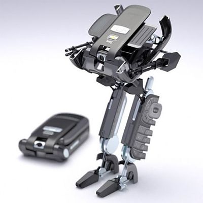
The robot is a machine with motion or manipulation abilities, so one of the most important problems to deal with is motion planning, which implies modelling the environment taking into account obstacles within, and the robot, as an entity with complex and variable shape. Motion planning can be considered as a problem of developing algorithms to automatically calculate a continuous trajectory for a set of objects, possibly interconnected, in order to move from one position to another, avoiding collisions with other stationary or moving objects.
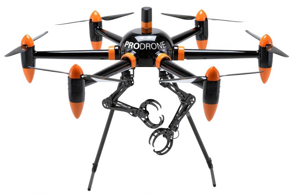
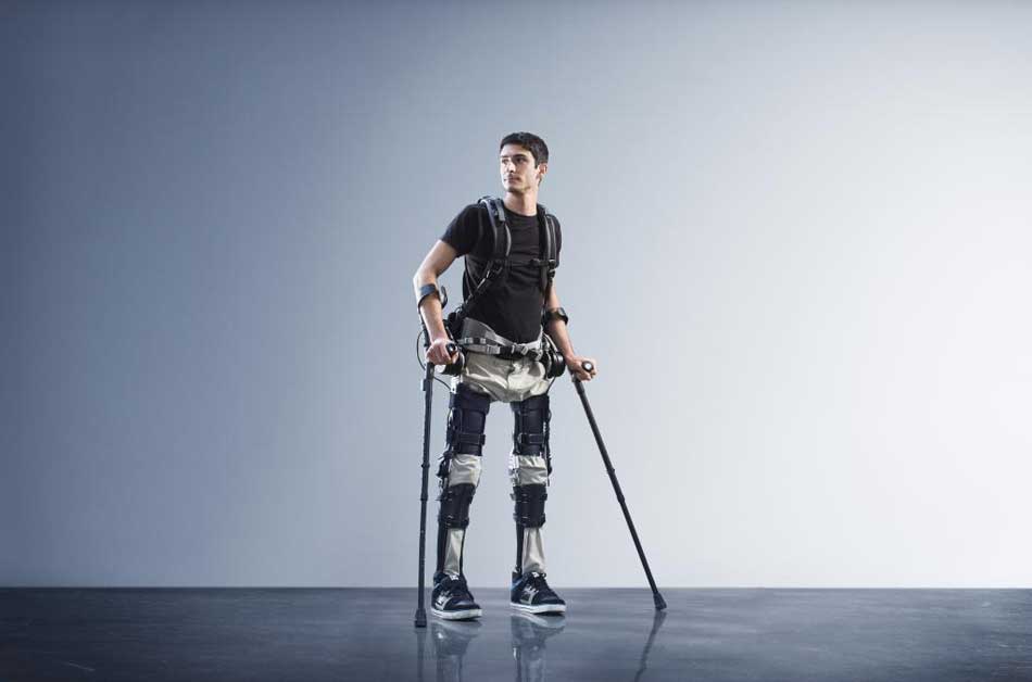
For a robot with a static base, the problem can be formulated in a much simpler fashion by choosing a trajectory for the robotic arm that does not interfere with items in a controlled environment. The higher the complexity of the robotic system and the more crowded the environment it operates in, the higher the complexity degree of the problem. Even when switching from a 2D to a 3D work space, all else remaining unchanged, raises the complexity of the problem significantly. The difficulty of the study increases even further if the robot is enabled with more degrees of freedom, as this implies a more complex architecture and a more difficult modelling of the robot and its environment.

Various types of 2D and 3D spatial representation have been used over the time, especially in computer aided design (CAD) applications, such as body geometry, limit representation, decomposition into cells or non-geometric subspaces, embodying volumes, decision trees and so forth. Most common techniques employed in numeric modelling are:
- parametric;
- structural geometry;
- limit representation;
- spatial enumeration;
- sweeping;
- analytic methods.
Elementary geometrical shapes, required to build complex solids, can be obtained through specialized functions found in professional design software or can be employed in designing 3D construction programs. Utilizing only standard primitives can limit the versatility of the system, thus it is necessary that the user has the means to define, according to his needs, primary geometrical entities. Curves can be created starting from points, surfaces can be created based on curves and volumes can be created based on surfaces.
The following two forms of representations are generally studied:
- Representation through parametric partitions – in which objects are represented precisely by means of polygonal curved networks, usually called “patches“;
- Representation through spatial subdivision – which means representing an object by associating cells from a space divided into equal and unequal cells, the association technique being based on methods in the graph theory or tree construction algorithms.
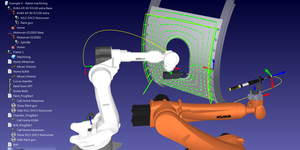
Complex shape bodies modelling can be achieved through both of the methods mentioned above, being employed in consumer programs as well as professional software. The first method is employed for reconstructing complex bodies, like robots or workspaces, while the second method is employed for solving planning problems, the work space of a robot being represented.
Parametric representations
Parametric representation methods are Bezier curves or B-spline, and they are utilized in the construction of other elements, such as surfaces. In numerical analysis a Bezier curve is in fact a parametric curve with many applications in computer aided design and related fields. General Bezier curves of higher order are also called Bezier surfaces, the Bezier triangle being a particular case of such. The Bezier curves method has surfaced in 1962 when the french engineer Pierre Bezier utilized it for the first time to design automobile chassis. The method hovewer has been studied since 1959 by Paul de Casteljau, with the aid of an algorithm developed by himself, the de Casteljau’s algorithm. This algorithm represented a numerically stable method of evaluation. Bezier curves are based on Bernstein polynomials.

The B-spline, or basis spline, is essentially a spline function with minimal support with respect to a given degree, smoothness and domain portion. They were first studied in the XIX-th century by Nikolai Lobachevsky. The B-splines can be studied in a numerically stable fashion with the aid of the de Boor algorithm.
A parametric curve is defined as a discrete set of points, also known as “control points“, together with a set of basic functions. This method of describing the curve is completely different to the standard mathematical method, which is represented by an implicit function.
Basic functions utilized to trace and set up the control points in a curve segment, can be represented by any set of any number of basic functions with various properties, employed in computer graphics to control the shape of a curve through an interactive interface.
Bezier curves present certain advantages, they are easy to use and objects can be represented if Bezier surfaces are used. Bezier curves also have certain disadvantages that can be overcomed by utilizing B-splines. Describing a curve segment, or a partition of a surface, through a set of control points is the basis of an interactive design method in CAD, the curve being traced with respect to known positions of these points. If the shape of the curve is not satisfactory, a new set of control points is specified and operations are repeated. This way curve segments are created that are employed in constructing a curve formed by these segments, joint together based on certain conditions of continuity.
In CAD there is a tendency to employ cubic curves. This is to the fact that these present enough shape flexibility for most applications, but also to the fact that a higher order curve can reclaim higher cost. They are however true spatial curves, unlike quadratic curves that can be contained withing a 2D plane. A curve composed of quadratic segments can be only a set of 2D segments. This is not satisfactory to 3D modelling.
Recent research has been made towards:
- Parametric representation of three dimensional curves:
- Bezier cubic curves;
- Joining Bezier cubic curve segments;
- Uniform and non-uniform B-splines.
- Biparametric cubic surface representation:
- Combining Bezier surface portions;
- B-spline surface portions;
- Editing parametric surfaces.
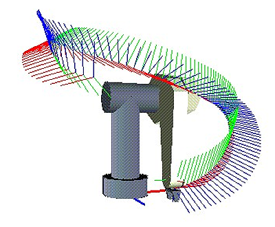
- Parametric representation of robot’s own workspace aided by Matlab:
- – functions utilized in Matlab scripts to generate graphs;
- – modelling surfaces described by final effector positions.
Resources
- Graph Theory, By K. Ruohonen at Tampere University of Technology
- B-spline, Wolfram MathWorld
- Bezier curve, Wolfram MathWorld
- “Computer-Aided Geometric Design and Computer Graphics: Bezier Curves and Surfaces” by A. Iglesias at University of Cantabria
- Bezier surfaces by D. Donavanik at University of Edinburgh
- Bezier triangle, Wikipedia
- Bezier surface, Wikipedia